Posted 06 April 2018,
As an enhancement to Wall-E2, my wall-following robot I wanted a way to capture the run time at power-down so I could determine how long it has been since Wall-E2 last charged its battery, even through power cycles.
At first I tried to do this using the Arduino Mega 2560’s onboard EEPROM, but this proved infeasible, as the time required to write to EEPROM exceeded the time available from the time power was removed to the time the Mega died. I played around with extra capacitance on the power bus, but this still wasn’t enough to hold the power up long enough to write to EEPROM. And, even if I finally succeeded, there was still the problem of EEPROM wear-out to deal with.
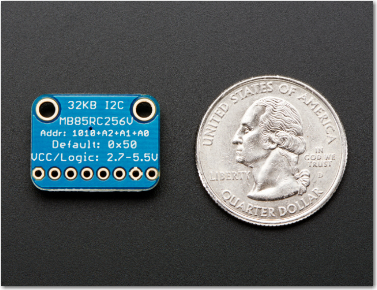
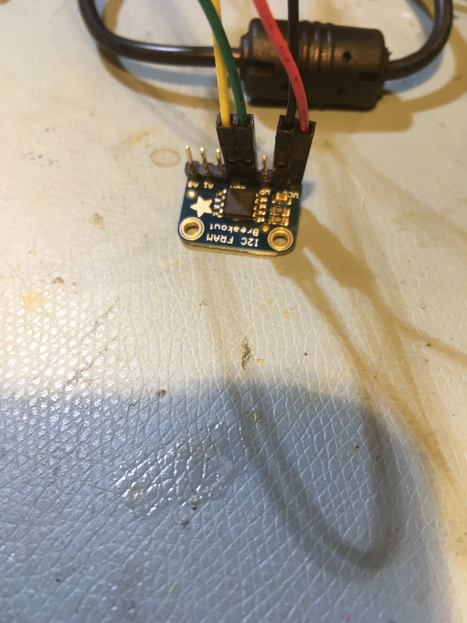
So, after some more research time with Google, I found this nice Adafruit FRAM breakout board, featuring the Fujitsu M85RC256V 32KB FRAM part
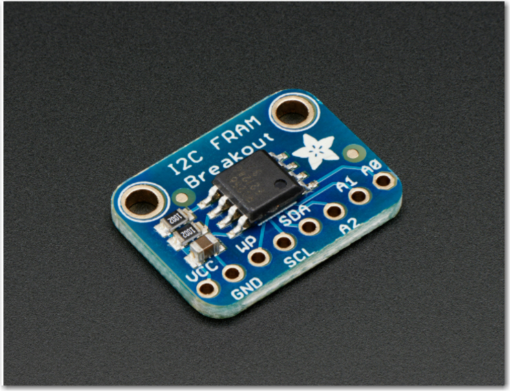
Adafruit provides a simple, but effective I2C interface library and an example sketch, and I was able to use these with a spare Arduino Uno board to verify that I could indeed write to and read from the FRAM. However, what I really wanted to determine was whether or not the FRAM was fast enough to allow me to write data to it after power was removed from the Arduino but before the processor actually died.
I did some poking around in the Arduinio Uno schematic and determined there was a 47μF capacitor on the output of the +5V voltage regulator, and so I thought I might be able to trigger off power loss at the input to the regulator and accomplish the writes while the capacitor was still holding up the Arduino processor. I put a 1/3:2/3 voltage divider on the +12V input line and used my trusty Tektronix 2236 scope to monitor it and the +5V regulated output. With the scope I was able to see that the +5V output stayed up for about 5msec, and stayed above 4V for 8msec, as shown in the following scope photo.
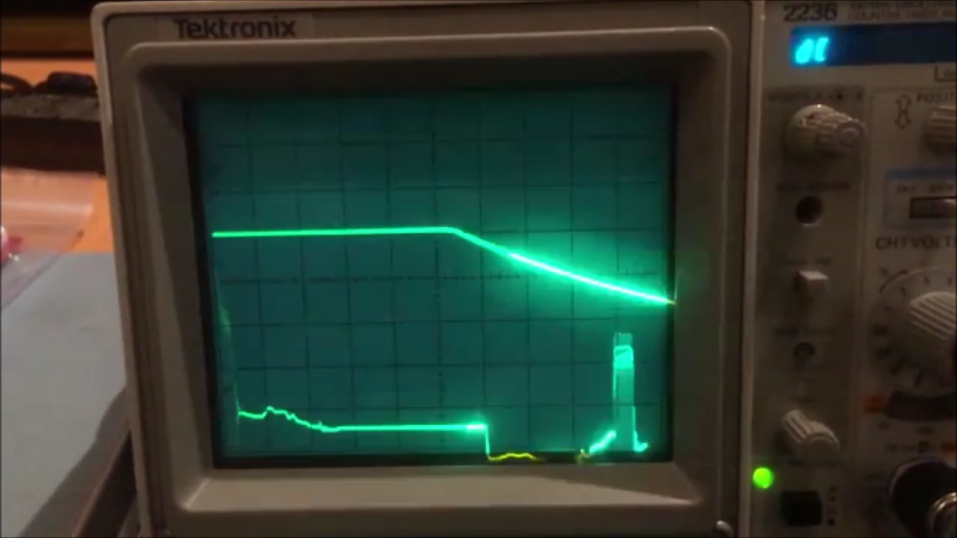
Scope photo of Arduino Uno +5V regulated output, triggered by removal of +12V input power. Time scale 1msec/div.
The next step was to modify Adafruit’s FRAM read/write example program to implement a power-down interrupt routine to test my idea. Here’s the code (the software is also available here)
|
1 2 3 4 5 6 7 8 9 10 11 12 13 14 15 16 17 18 19 20 21 22 23 24 25 26 27 28 29 30 31 32 33 34 35 36 37 38 39 40 41 42 43 44 45 46 47 48 49 50 51 52 53 54 55 56 57 58 59 60 61 62 63 64 65 66 67 68 69 70 71 72 73 74 75 76 77 78 79 80 81 82 83 84 85 86 87 88 89 90 91 92 93 94 95 96 97 98 99 100 101 102 103 104 105 106 107 108 109 110 111 112 113 114 115 116 117 118 119 120 121 122 123 124 125 126 127 128 129 130 131 132 133 134 135 136 137 138 139 140 141 142 143 144 145 146 147 148 149 150 151 152 153 154 155 156 157 158 |
#include <Wire.h> #include "MyAdafruit_FRAM_I2C.h" /* Example code for the Adafruit I2C FRAM breakout */ /* Connect SCL to analog 5 Connect SDA to analog 4 Connect VDD to 5.0V DC Connect GROUND to common ground */ MyAdafruit_FRAM_I2C fram = MyAdafruit_FRAM_I2C(); uint16_t framAddr = 0; volatile uint8_t testval; const int InterruptPin = 2; const int RestartCountAddr = 0x0; volatile byte state = LOW; byte last_state = state; const byte ledPin = 13; const int CLEAR_FRAM_PIN = 3; const int NUM_LOCS_TO_CLEAR = 100; int nextFramWriteAddr = 2; //addr 0 reserved for restart count, addr 1 is unusable (don't know why) const int NUM_TIMES_TO_DISPLAY = 10; bool InSetup = true; void setup(void) { Serial.begin(2000000); if (fram.begin()) { // you can stick the new i2c addr in here, e.g. begin(0x51); Serial.println("Found I2C FRAM"); } else { Serial.println("I2C FRAM not identified ... check your connections?\r\n"); Serial.println("Will continue in case this processor doesn't support repeated start\r\n"); } // Read the first byte fram.FRAM_I2C_readAnything(RestartCountAddr, testval); Serial.print("Restarted "); Serial.print(testval); Serial.println(" times"); fram.FRAM_I2C_writeAnything(RestartCountAddr, testval + 1); Serial.println("Displaying contents of first 50 memory locations... "); uint8_t value; for (uint16_t a = 0; a < 50; a++) { fram.FRAM_I2C_readAnything(a, value); if ((a % 32) == 0) { Serial.print("\n 0x"); Serial.print(a, HEX); Serial.print(": "); } Serial.print("0x"); if (value < 0x1) Serial.print('0'); Serial.print(value, HEX); Serial.print(" "); } Serial.println(); pinMode(InterruptPin, INPUT_PULLUP); pinMode(ledPin, OUTPUT); pinMode(CLEAR_FRAM_PIN, INPUT_PULLUP); int intnum = digitalPinToInterrupt(InterruptPin); Serial.print("Using interrupt number "); Serial.println(intnum); attachInterrupt(intnum, FRAM_ISR, FALLING); interrupts(); //optionally clear FRAM locations if (digitalRead(CLEAR_FRAM_PIN) == LOW) { Serial.print("Clearing "); Serial.print(NUM_LOCS_TO_CLEAR); Serial.println(" FRAM addresses..."); byte clearval = 0; for (size_t i = 0; i < NUM_LOCS_TO_CLEAR; i++) { fram.FRAM_I2C_writeAnything(i, clearval); } //now read them back DisplayMemory(NUM_LOCS_TO_CLEAR); } else { DisplayTimes(nextFramWriteAddr, NUM_TIMES_TO_DISPLAY); } Serial.print("Enabling Power-down ISR, Entering Loop() with millis() = "); Serial.println(millis()); InSetup = false; //enable power-down ISR } void loop(void) { digitalWrite(ledPin, state); if (state != last_state) { Serial.println("Changed..."); last_state = state; DisplayMemory(32); DisplayTimes(nextFramWriteAddr, 10); } delay(100); //Serial.print(millis()); Serial.print(": nextFramWriteAddr = "); Serial.println(nextFramWriteAddr); } void DisplayMemory(int lastAddr) { Serial.print("\nDisplaying memory locations 0 to "); Serial.println(lastAddr); uint8_t value; for (uint16_t a = 0; a < lastAddr; a++) { //value = fram.read8(a); fram.FRAM_I2C_readAnything(a, value); if ((a % 16) == 0) { Serial.print("\n 0x"); Serial.print(a, HEX); Serial.print(": "); } Serial.print("0x"); if (value < 0x1) Serial.print('0'); Serial.print(value, HEX); Serial.print(" "); } Serial.println(); } void DisplayTimes(int startaddr, int numtimes) { Serial.print("\nDisplaying first "); Serial.print(numtimes); Serial.print(" stored times starting at "); Serial.println(nextFramWriteAddr); long value = 0; for (uint16_t i = 0; i < numtimes; i++) { //value = fram.read8(a); int addr = nextFramWriteAddr + i * sizeof(value); int numbytes = fram.FRAM_I2C_readAnything(addr, value); //starts at addr 1 //Serial.print(i + 1); Serial.print(": "); Serial.println(value); Serial.print(addr); Serial.print(": "); Serial.println(value); } } void FRAM_ISR() { static boolean IsRunning = false; if (IsRunning || InSetup) return; //we have been interrupted while already processing an interrupt - ignore this ocurrence IsRunning = true; //Depending on the interrupt source, you may need to clear the interrupt flag here. Most Arduino interrupts are self-clearing. state = !state; interrupts(); //re-enable interrupts so that interrupt-based functions can be used inside this function //'infinite' loop (that is, until the Uno dies....) while(1) { for (size_t i = 0; i < 1000; i++) { long timeMs = millis(); //interrupts are enabled, so this should work... int numbyteswritten = fram.FRAM_I2C_writeAnything(nextFramWriteAddr, timeMs); nextFramWriteAddr += numbyteswritten; } } noInterrupts(); //turn off interrupts so we can't be interrupted while resetting our special variable IsRunning = false; } |
The above code takes advantage of a modified version of Adafruit’s I2C FRAM library that facilitates writing and reading of arbitrary data types like int, long, float, etc. The modifications were cribbed from Nick Gammon’s wonderful ‘IC2_Anything’ library – thanks Nick!
Here’s the modified ‘Adafruit_FRAM_I2C.h’ file
|
1 2 3 4 5 6 7 8 9 10 11 12 13 14 15 16 17 18 19 20 21 22 23 24 25 26 27 28 29 30 31 32 33 34 35 36 37 38 39 40 41 42 43 44 45 46 47 48 49 50 51 52 53 54 55 56 57 58 59 60 61 62 63 64 65 66 67 68 69 70 71 72 73 74 75 76 77 78 79 80 81 82 83 84 85 86 87 88 |
/**************************************************************************/ /*! @file Adafruit_FRAM_I2C.h @author KTOWN (Adafruit Industries) @section LICENSE Software License Agreement (BSD License) Copyright (c) 2013, Adafruit Industries All rights reserved. Redistribution and use in source and binary forms, with or without modification, are permitted provided that the following conditions are met: 1. Redistributions of source code must retain the above copyright notice, this list of conditions and the following disclaimer. 2. Redistributions in binary form must reproduce the above copyright notice, this list of conditions and the following disclaimer in the documentation and/or other materials provided with the distribution. 3. Neither the name of the copyright holders nor the names of its contributors may be used to endorse or promote products derived from this software without specific prior written permission. THIS SOFTWARE IS PROVIDED BY THE COPYRIGHT HOLDERS ''AS IS'' AND ANY EXPRESS OR IMPLIED WARRANTIES, INCLUDING, BUT NOT LIMITED TO, THE IMPLIED WARRANTIES OF MERCHANTABILITY AND FITNESS FOR A PARTICULAR PURPOSE ARE DISCLAIMED. IN NO EVENT SHALL THE COPYRIGHT HOLDER BE LIABLE FOR ANY DIRECT, INDIRECT, INCIDENTAL, SPECIAL, EXEMPLARY, OR CONSEQUENTIAL DAMAGES (INCLUDING, BUT NOT LIMITED TO, PROCUREMENT OF SUBSTITUTE GOODS OR SERVICES; LOSS OF USE, DATA, OR PROFITS; OR BUSINESS INTERRUPTION) HOWEVER CAUSED AND ON ANY THEORY OF LIABILITY, WHETHER IN CONTRACT, STRICT LIABILITY, OR TORT (INCLUDING NEGLIGENCE OR OTHERWISE) ARISING IN ANY WAY OUT OF THE USE OF THIS SOFTWARE, EVEN IF ADVISED OF THE POSSIBILITY OF SUCH DAMAGE. */ /**************************************************************************/ #ifndef _ADAFRUIT_FRAM_I2C_H_ #define _ADAFRUIT_FRAM_I2C_H_ #if ARDUINO >= 100 #include <Arduino.h> #else #include <WProgram.h> #endif #include <Wire.h> #define MB85RC_DEFAULT_ADDRESS (0x50) /* 1010 + A2 + A1 + A0 = 0x50 default */ #define MB85RC_SLAVE_ID (0xF8) class MyAdafruit_FRAM_I2C { public: MyAdafruit_FRAM_I2C(void); boolean begin(uint8_t addr = MB85RC_DEFAULT_ADDRESS); void write8 (uint16_t framAddr, uint8_t value); uint8_t read8 (uint16_t framAddr); void getDeviceID(uint16_t *manufacturerID, uint16_t *productID); //Additions to facilitate read/write of arbitrary data types //G. Frank Paynter, April 2018 // Original I2C_Anything.h written by Nick Gammon, May 2012 template <typename T> unsigned int FRAM_I2C_writeAnything(uint16_t framAddr, const T& value) { const byte *p = (const byte*)&value; unsigned int i; for (i = 0; i < sizeof value; i++) { write8(framAddr++,*p++); } return i; } // end of I2C_writeAnything template <typename T> unsigned int FRAM_I2C_readAnything(uint16_t framAddr, T& value) { byte * p = (byte*)&value; unsigned int i; for (i = 0; i < sizeof value; i++) *p++ = read8(framAddr++); return i; } // end of I2C_readAnything private: uint8_t i2c_addr; boolean _framInitialised; }; #endif |
With this test setup, I was able to repeatedly clear the FRAM memory and see the effect of pulling the power plug. A typical result is shown below:
Program response when restarted with CLEAR_FRAM_PIN (pin 3) grounded
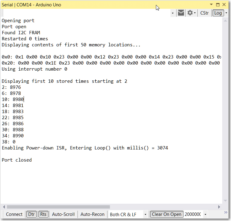
Program response after the power plug was pulled at about 8.9 sec after startup.
In the first figure above, the CLEAR_FRAM_PIN (pin 3) was held LOW while the Arduino was restarted, resulting in zeroes being written to the first 100 FRAM locations. In the second figure, the +12V power plug was pulled after about 9 seconds, then reconnected. When the Arduino restarted, the power-down ISR had written program timer values from 8976 to 8990 into the first nine 4-byte segments. This shows that the Arduino continued to operate for about 14msec after the power plug was removed. This is very good news, as it implies that I should be able to write the current date/time value from a real-time clock (when I get it running, that is) into FRAM whenever there is a power interruption, allowing me to accurately track battery usage history.
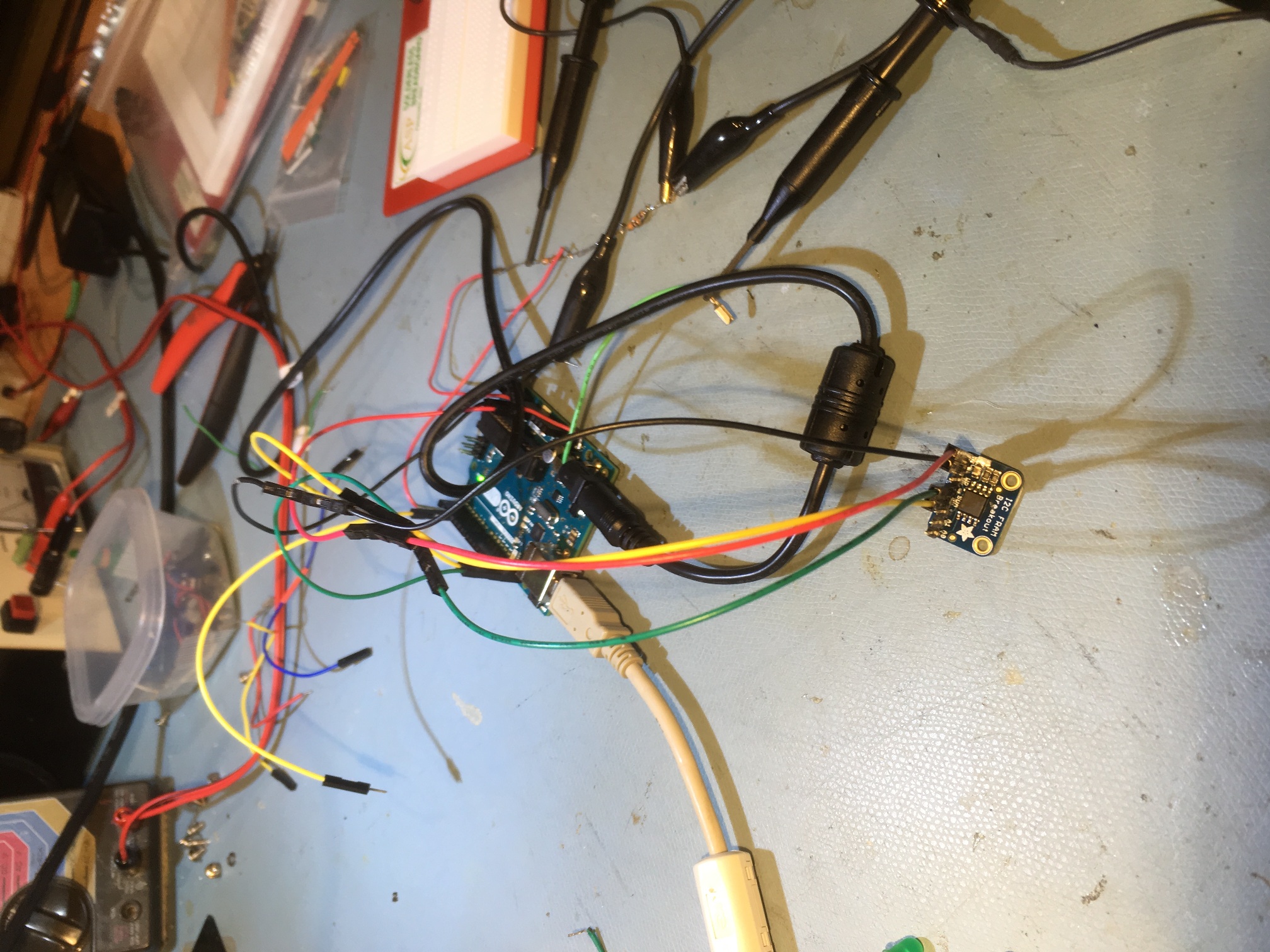
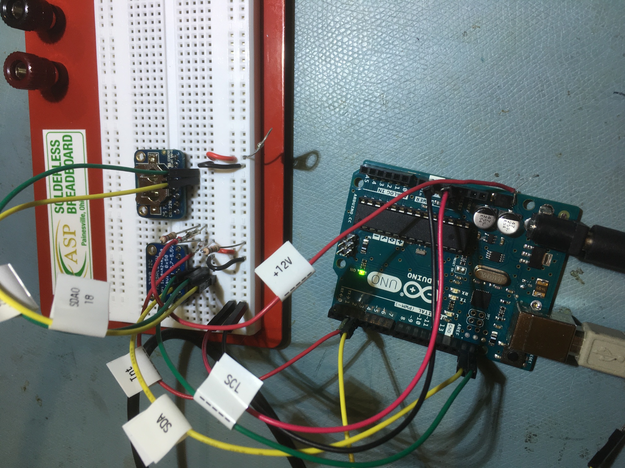
The hardware used to perform these tests is shown in the following photos:
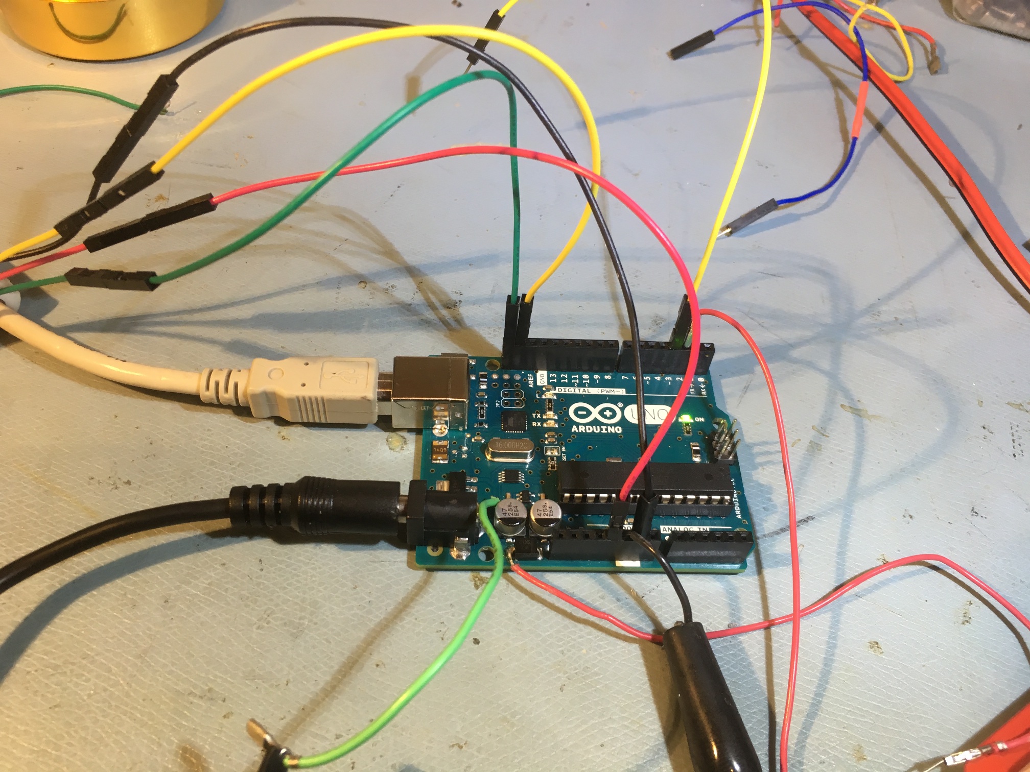
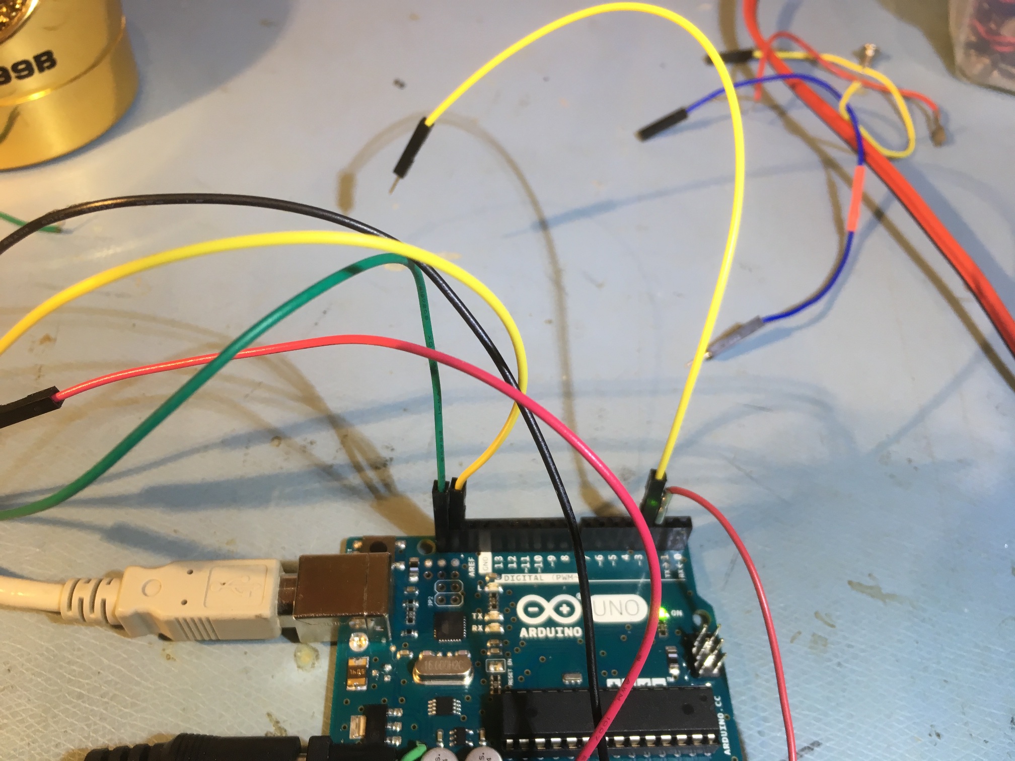
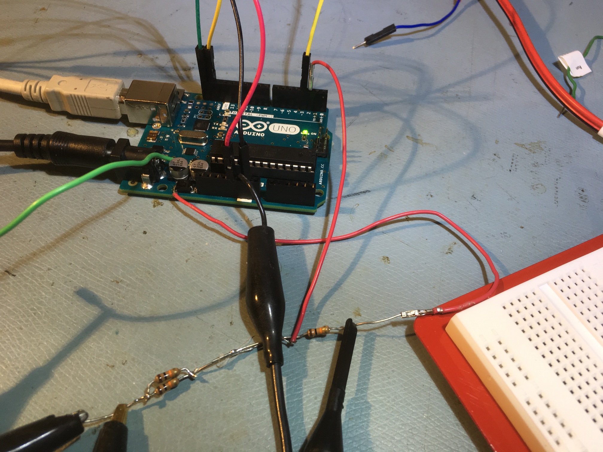
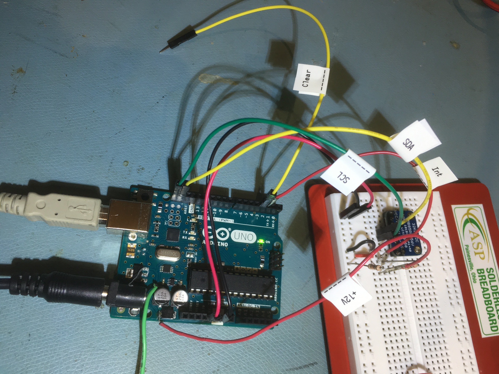
Experimental setup moved to new ASP solderless breadboard
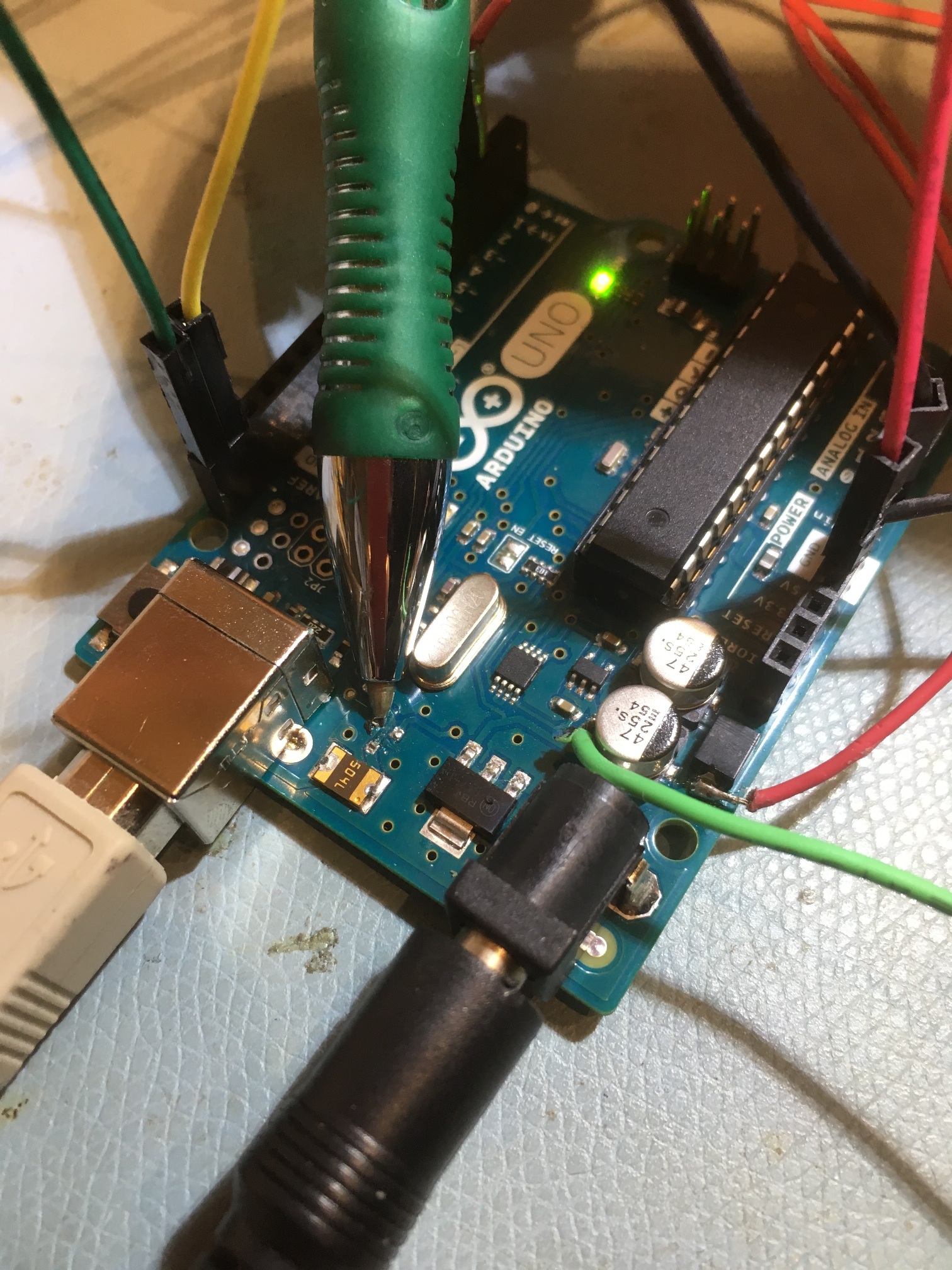
Arduino Board Modification:
I ran into a problem when I started testing the power-down interrupt idea; I wanted to keep thE Arduino board connected to my PC via the USB cable, but if I did that, the Arduino would automatically switch over to USB power when I disconnected the +12V power cable. Fortunately, if you have a problem, it’s almost certain that someone else has had and solved the same problem. In my case I found this post, that explained that T1, the automatic power crossover MOSFET switch had to be removed, as shown in the following photo. This modification allows the USB cable to continue to supply USBVCC power to U3, the ATMEGA8U2-MU chip, which in turn allows the PC to recognize the Arduino for firmware uploads.
 Loading...
So, now that I have demonstrated the practicality of a power-down interrupt routine to capture time-of-shutdown information (at least on an Arduino Uno), the next step is to integrate this capability with the Adafruit RS3231 Precision RTC breakout board. Stay tuned!
09 April Update: Adafruit DS3231 RTC breakout board added:
As I mentioned in my ‘Time and Memory for Wall-E2‘ post, I planned to complement the FRAM capability with the addition of an RTC module so that I could record the time & date of any power interruptions. As I mentioned in that post, I planned to use the Adafruit DS3231 Breakout Board for this purpose. After receiving the module, I added it to the system by daisy-chaining the I2C SCL & SDA lines from the FRAM module, and modified the software to incorporate the RTC. I changed the FRAM_ISR() function to acquire ‘Unixtime’ from the RTC (i.e. the number of seconds since 00:00:00 UTC on January 1, 1970) and write it to the FRAM.
I tested this by uploading this firmware to the Arduino Uno, and then pulling the power plug a few seconds after the program entered the main loop. Here’s the printout from the run
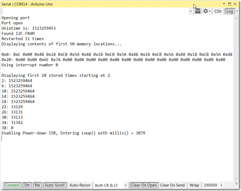
Program run with Adafruit DS3231 RTC added. Note ‘unixtime’ printout at top, and first 5 FRAM locations at bottom
As can be seen from the above printout, the power-down ISR successfully recorded the current time (in ‘Unixtime’ format) into five successive FRAM memory locations before the Arduino died. Note also that the recorded time was eleven seconds after the time shown at the top of the printout – about right, as the upper value is the time retrieved using the PC’s __DATE__ and ___TIME___ environment variables at the time the program was compiled and uploaded to the Arduino board.
Here are some photos of the new hardware setup:
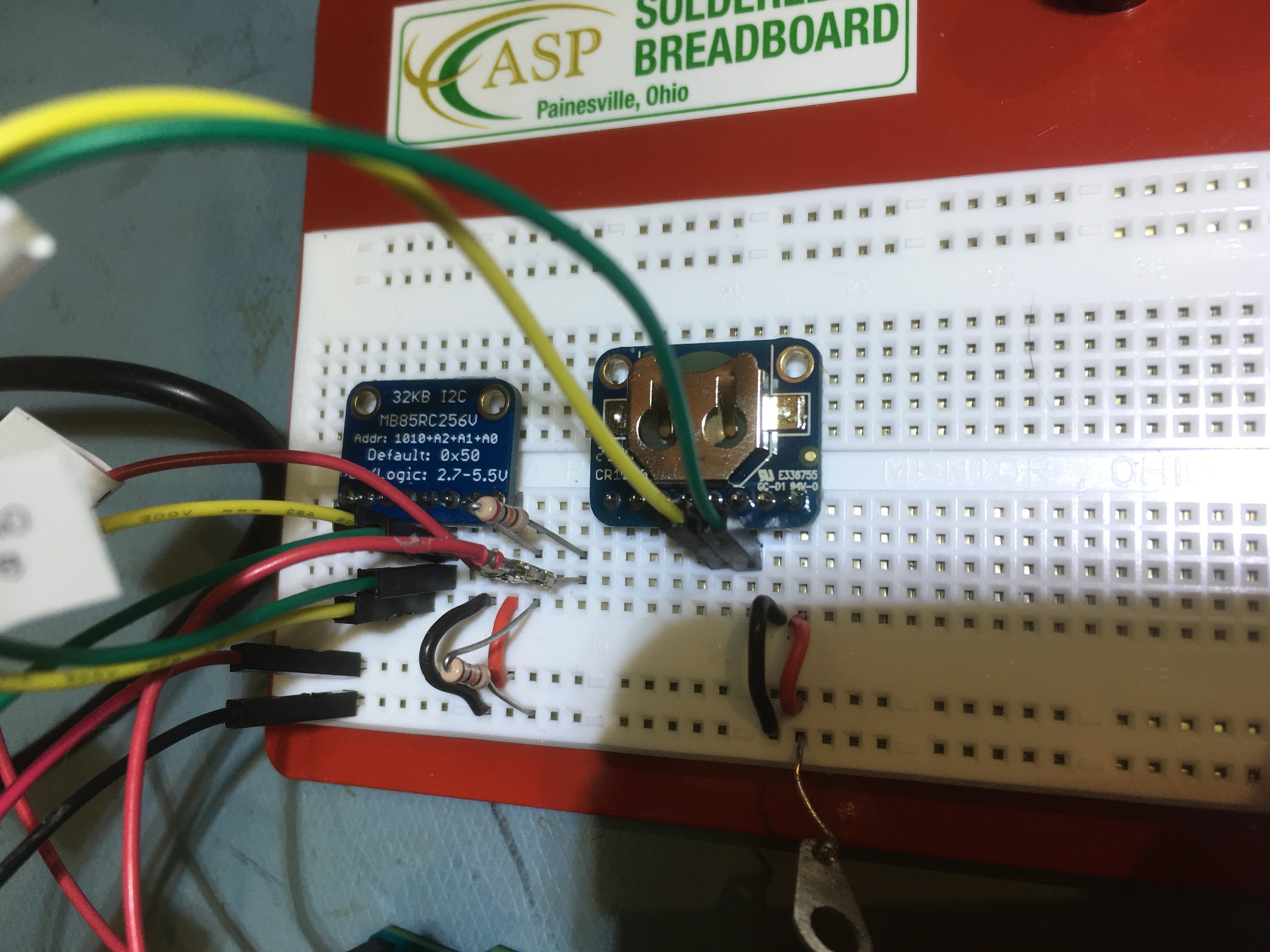
Adafruit FRAM module on the left, DS3231 RTC module on the right
Frank
Pingback: Another try at heading information for Wall-E2 - Paynter's Palace
Pingback: Integrating Time, Memory, and Heading Capability - Paynter's Palace