Posted 17 March 2018,
To paraphrase the saying, “to a man with a hammer, every problem looks like a nail”, “to a man with a 3D printer, every problem looks like a 3D printing opportunity”. And that’s pretty much what happened when I ran across the problem of adapting some 80mm wheels to my Wall E-2 robot, which came originally with 65mm versions. The extra 15mm diameter/7.5mm radius doesn’t sound like much, but it makes a huge difference when navigating over carpet or other small obstacles (like my wife’s slippers).
After a lot of work, I finally was able to print four reasonable quality adaptors, and thought I was home free. Unfortunately, I soon learned that despite my best efforts, the printed adaptors were no match for physics; the wheel eventually worked its way off the motor shaft, just as before – it just took a little longer ;-).
After the usual number of curses, imprecations, and woe-is-me’s, I finally decided to use whatever was left of my engineering brain to actually look at the physics of the situation. When I did so, I realized that my adaptor idea was never going to work. While the adaptor did indeed (after the aforementioned ‘lot of work’) provide for a better fit between the 80mm wheel receptacle and the motor shaft, it also moved the wheel another 9mm or so away from the robot chassis, which put the wheel center of pressure (CP) well outside the adaptor-to-motor shaft parting plane. This meant that the wheel would always be trying to pry the the adaptor off the shaft, and it didn’t take all that long for it to succeed :-(. The following photo illustrates the problem
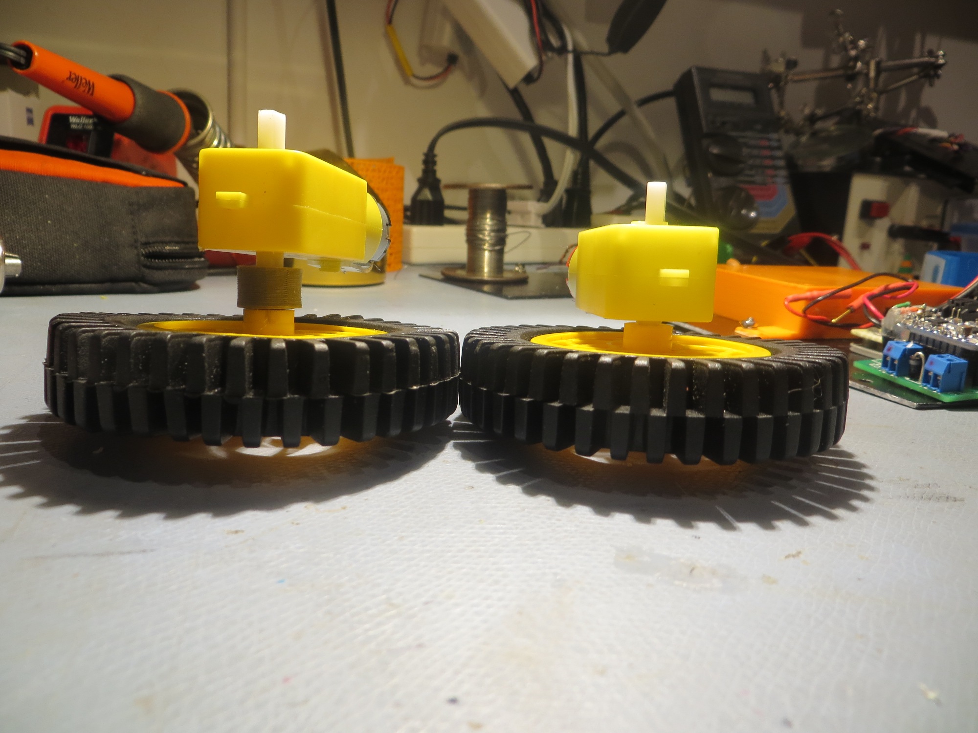
80mm wheel with 3D-printed adaptor on the left, same wheel directly attached to motor shaft on the right
So, contemplating this problem while drifting off to sleep I was struck by a solution; I could use a small roll pin inserted through the wheel and motor shafts to literally pin them together. The geometrical physics would still cause the wheel to flex the shaft, but the forces wouldn’t be able to overcome the strength of the metal roll pin. Because I knew I would forget this insight if I left it until morning, I staggered out of bed and jumped onto the McMaster-Carr site (they have everything!) to look for an appropriately sized roll pin. I found a 1 x 6mm roll pin that would be perfect for the job, and if I ordered them now they would probably already be on my doorstep when I woke up in the morning.
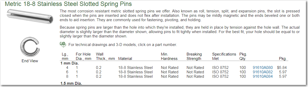
McMaster-Carr metric roll pins
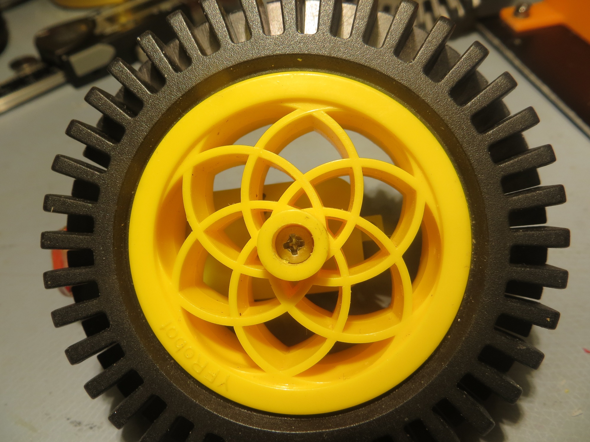
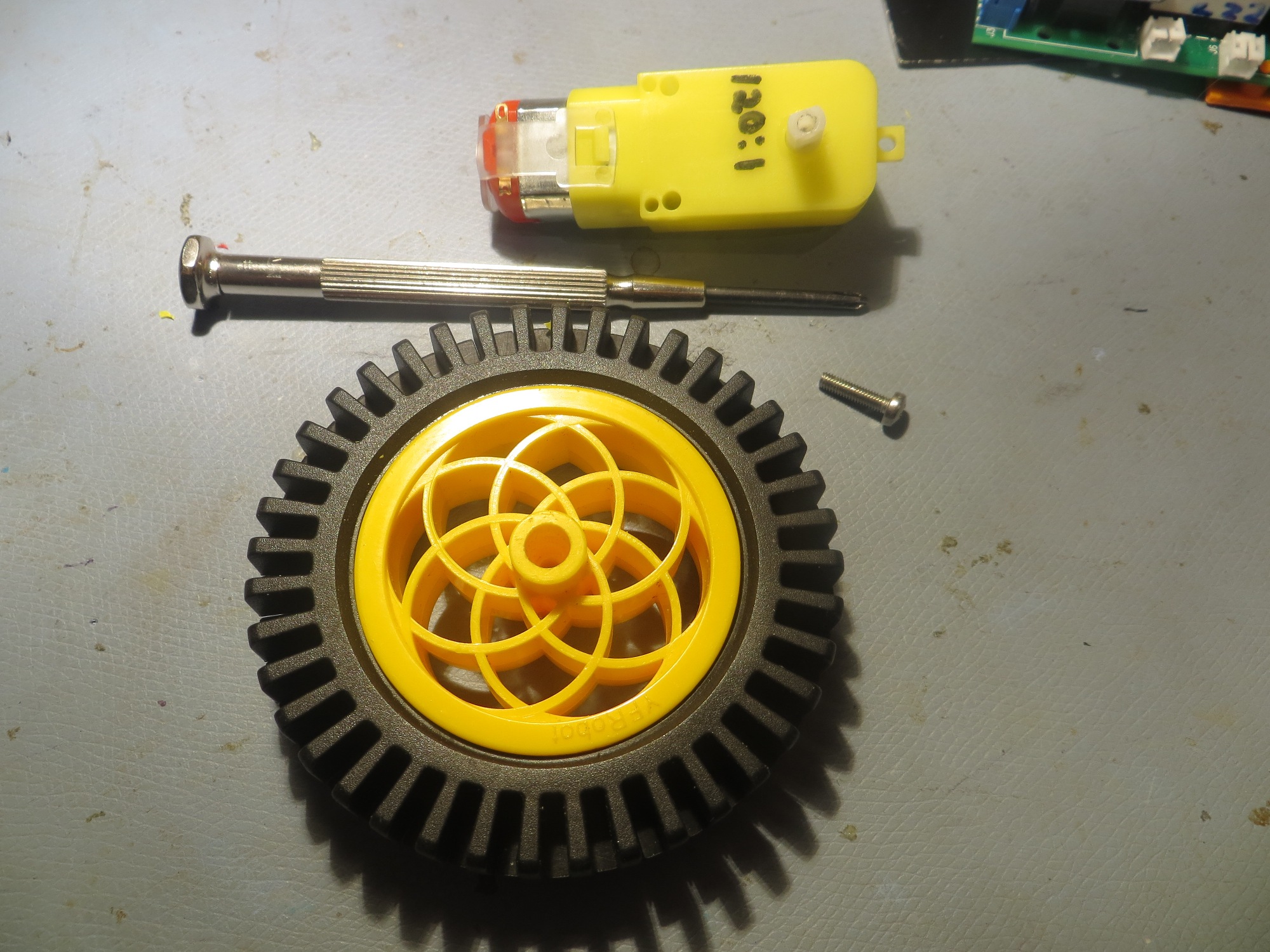
However, while I was doing the necessary measurements on the motor shaft, I noticed the motor shaft had a axial hole in it, and so did the wheel; hmm, maybe I could simply run the roll pin through the axial hole, instead of cross-wise? Then I thought – wait that hole looks to be slightly smaller than 3mm – maybe I could simply drill/tap it for 3mm and use a 3mm screw (of which I had plenty in different lengths) instead of a roll pin?
So, in just a few minutes I had drilled & tapped the axial hole in the motor shaft of one of my spare motors, drilled out the wheel hole for 3mm clearance, and firmly screwed the wheel to the shaft (the right-hand wheel in the first photo above) – cool!
Now all I have to do is modify all four wheel shafts for 3mm clearance, and all four motor shafts to accept a 3mm screw – piece of cake!
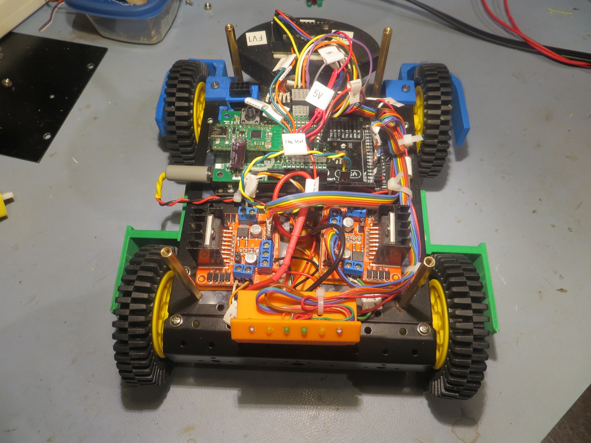
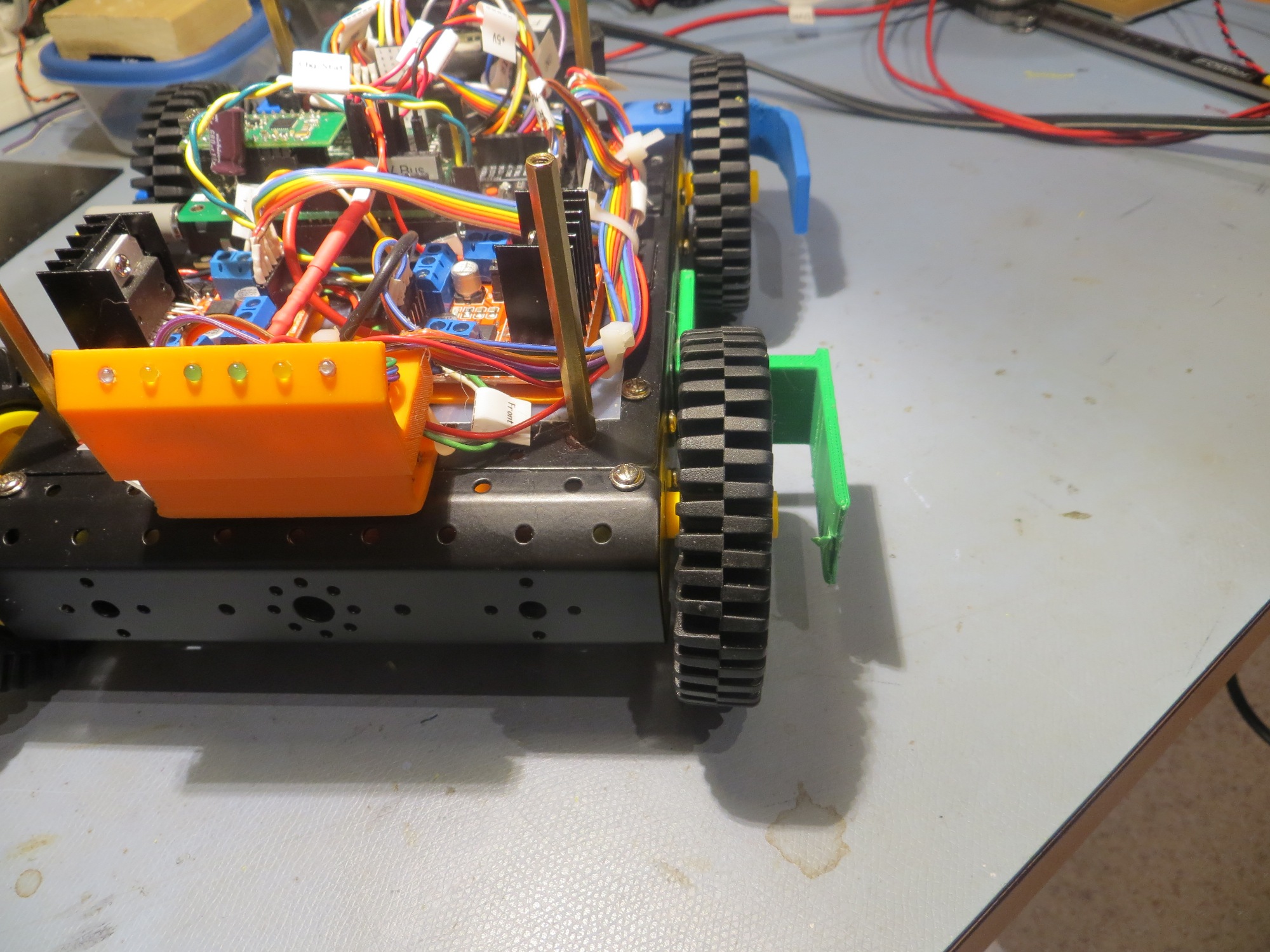
As can be seen in the above photos, the 80mm wheels are now much closer to the chassis. The wheel guards are now much too wide, but I may keep them that way for the moment, as I have already adjusted the charging station lead-in rails to accommodate the (now unnecessary) greater wheelbase – oh well 😉
So, the moral of this little story is: Just because you have a 3-D printer doesn’t mean the solution to every problem is a new 3-D printed piece; and maybe to keep one’s eyes/brain open for even better solutions as they might come along when least expected!
Stay tuned,
Frank