
Posted 30 July 2017
This long-running saga started actually started almost exactly two months ago with the weekend visit of my friend and long-time mentor John Jenkins. Naturally, being fellow geeks, I showed him all my new toys, including Wall-E2, my autonomous wall-following robot. When I explained that Wall-E2 was having some trouble homing in on an IR beacon to connect to a charging station due to the ‘flooding’ effect of direct sunlight and overhead incandescent lighting (see for instance, this post), John opined that the way to address this problem was to modulate the homing beacon with a square wave, and then use a ‘simple’ digital filter on the robot to better discriminate between the wanted (square-wave modulated) and unwanted (sunlight and/or incandescent lighting) sources.
Right then and there I should have realized I was in trouble, because I have (or should have!) learned over the years that whenever John uses the word ‘simple’, what he really means is “this is going to be so complex that you will wish you never listened to me”, and what he means by the word ‘better’ is “this will make your robot capable of operating from the vacuum of space to the depths of the ocean, in the middle of a thermonuclear war. All other life on earth will have long since been reduced to its constituent atoms before your robot fails to meet spec”. What I should have done was say to John “that’s nice John, but I think I’ll just operate Wall-E2 at night with the lights off”
But noooo, I fell for this line, (again!), and said “hmm, sounds interesting John”, thus going down yet another rabbit hole in my quest to make Wall-E2 completely autonomous. So now I started working on the design and implementation of a ‘degenerate N-path band pass filter’ (John’s term), a project tangential to the implementation of a charging station, which in itself was tangential to my original wall-following robot project. My only justification (well justifications) for this clearly insane behavior are:
- I am clearly insane – I’m a twice-retired engineer, after all!
- The entire impetus for the Wall-E2 project was to give me a way to waste as much time as possible in an intellectually stimulating way, and the idea of implementing a ‘degenerate N-path band pass filter’ promised to waste a lot of time (and besides, being able to tell people I had implemented a “degenerate N-path band pass filter” was just too sexy to pass up!)
Well, it has been a heck of a journey these last two months, but I believe that with John’s help (or possibly in spite of it), we now have a working two-channel 520Hz N-path BPF, and as a bonus – a working high-accuracy frequency/amplitude sweep generator, both based on Paul Stoffregen’s wonderful Arduino-ish Teensy 3.5 SBC. The last piece of the puzzle for the sweep generator design fell into place just yesterday with a post from ‘tni’ on the Teensy user forum, describing the proper technique for updating the count-down value for the Periodic Interrupt Timer (PIT) used in the sweep generator.
Sweep generator recap:
The original plan for the sweep generator was to use the same ‘elapsedMicros’ object type that I had used to generate the transmit waveform, but it turned out (see this post) that t he ‘elapsedMicros’ technique produced an unavoidable frequency offset. So, searching for other alternatives, I tried a rounding technique using ‘elapsedMicros’ which helped somewhat but didn’t really solve the problem, and then a method using Daniel Gilbert’s IntervalTimer library (this library wraps access to the Periodic Interrupt Timer (PIT) module of the FreeScale Cortex-M4 microcontoller used in the Teensy 3.x line). This technique produced a very accurate frequency output, but unfortunately also produced bad artifacts in the frequency response curves from the N-path BPF implementation due to the delays inherent in the need to stop and then restart the PIT for each new frequency step. A representative ‘raw’ and ’round-trip’ frequency response curve set is shown below to illustrate the problem, along with the timestamp representation of the PIT operation.
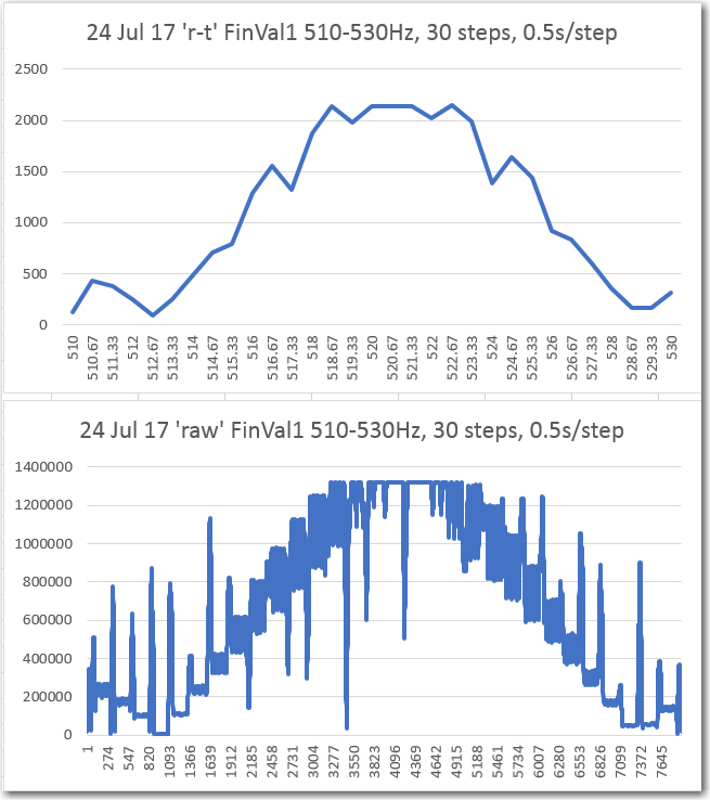
‘Round-trip’ and ‘raw’ FinalValue vs Frequency, with IntervalTimer technique
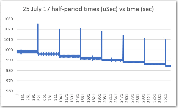
Square-wave transition times vs time using the IntervalTimer technique
I was just about ready to give up on the IntervalTimer technique, and just deal with the frequency offset inherent in the ‘elapsedMicros’ technique. However, John shamed me into putting a post up on the Teensy forum explaining my issues and asking for help. I hate to say it but I’m glad he did, as among the other helpful posts was one from ‘tni’ with the complete code for an add-on function to the IntervalTimer library to do just what I wanted – update the count-down count in the PIT without disturbing anything else. As a result of this addition, I was able to get frequency-accurate response curves from the IR demodulator filter without any ugly artifacts, as shown below
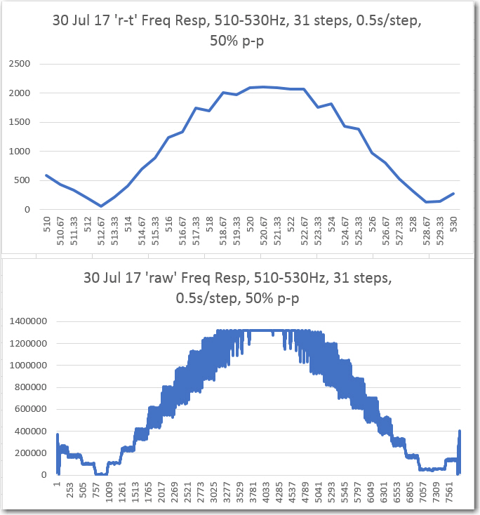
‘Round-trip’ and ‘raw’ FinalValue vs Frequency, with IntervalTimer technique, using tni’s updateInterval() function
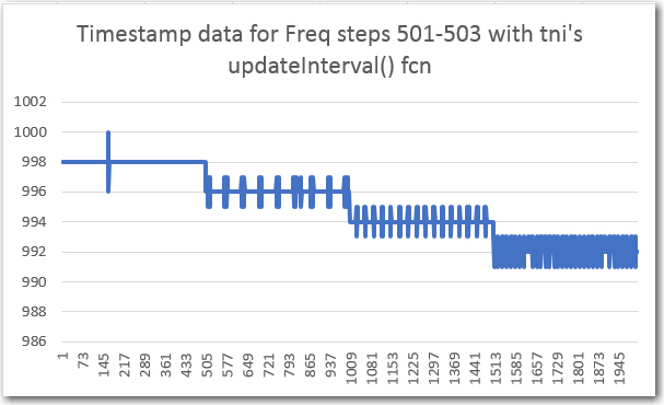
Square-wave transition times vs time using the IntervalTimer technique, using tni’s updateInterval() function
So now I have a sweep generator that works – albeit one that needs a little cleanup before I push it up to GitHub
August 02 2017 Update:
Today I finally ‘finished’ (to the extent that I ever really finish anything) the 2-channel IR demodulator algorithm, and the accompanying frequency/amplitude sweep generator, and posted both to my GitHub account (see https://github.com/paynterf/SqWaveIQDemodV2 and https://github.com/paynterf/TeensySweepGen). After squashing a few last buglets, I was able to run fairly detailed frequency sweeps on both demodulator channels using the sweep generator, with the following results
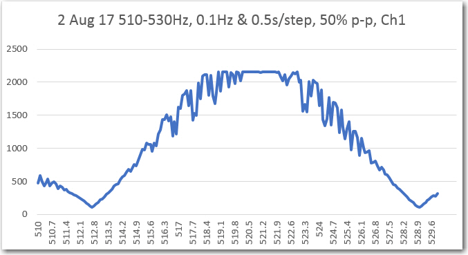
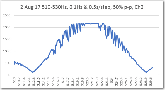
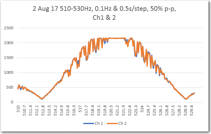
If you like data, this is pretty good stuff – nice and smooth, no unusual artifacts, nicely centered around 520-522Hz, and the Ch1/Ch2 overlap is almost perfect. Whatever else has happened in this little 2-month vacation from reality, the ‘N-path band pass filter’ algorithm clearly works, at least on the bench.
Now that I have the BPF algorithm humming along, the next challenge will be to integrate the BPF module onto the robot, and modify the charging station to modulate the IR homing beacon with the requisite 520Hz square wave, and of course test it all to verify functionality. Still plenty of work to do, so I don’t have to worry about getting bored anytime soon! Stay tuned…
Frank
Pingback: IR Homing Module Integration, Part I - Paynter's Palace
Pingback: Wall-E3 Replacing Mega 2560 With Teensy 3.5 Part III | Paynter's Palace