
Posted 15 January 2017
I received my sample spring finger contacts from TE Connectivity, but they are clearly not going to do the job as the fixed end of Wall-E2’s under-belly contact system – bummer. Even the 4mm high one is just too small – bummer :-(.
As usual, when faced with a setback, I go away and sulk for a while, and then come back with some more ideas. I may not be all that smart, but I am persistent! ;-). This time, after some more web research, I found a family of spring-loaded plunger contacts made by Mill-Max Inc, one of which is shown in the image below

Spring-loaded contact. Initial height is 7.67mm, compresses down to about 6mm
As an interesting aside, the Mill-Max components are (AFAICT) dimensioned entirely in English units (inches), which is of course what I grew up on here in the U.S. However, after the last few years of immersion in the 3D printing and robotics world, I have gotten to the point where I had to convert the above ‘0.302″‘ dimension into metric units (around 7.6mm) before I could visualize how (or even whether) it was going to fit into the current design. Even more interesting, I was an electronics design engineer in a DoD outfit during the Carter administration’s failed attempt in the 1970’s to convert the entire U.S. to metric. There was an enormous amount of work put into relabeling everything with both English and metric notation, to absolutely no effect. The reason it failed then, and is working now (at least for me) is the widespread use of metric notation now for 3D printing and DIY robotics. Way to go, Carter – you had the right idea, just 50 years too soon! ;-).
Anyway, back to the movie; while waiting for the above parts to arrive, I have been doing some additional work on the alternative plug-capture strategy, and came up with three additional design issues that must be resolved for either the bottom contact array or the front plug-capture methods.
- In order for either method to work, the robot has to know when the contacts have engaged, so it can change from a wall-following to a charge-monitoring strategy.
- The robot’s controller has to continue operating through the change from battery power to off-board charging power. The transition from battery power to off-board charging power is inherently seamless, as charging power to the Mega’s +5V (beyond the voltage regulator stage) pin appears before the batteries are switched from series to parallel for charging.
- When charging is complete, the robot has to somehow disengage from the charging system. This turns out to be somewhat of a trapeze act, as motor power to do the disengaging isn’t available until after disengaging – oops!
- Although the transition from battery to charging power is inherently seamless, the opposite transition isn’t. 5V power from the charger goes away before battery power becomes available, causing the Mega to reboot – double oops!
Knowing when contacts have engaged
For the robot to know when the contacts have engaged, there has to be some electrical signal that changes state when this happens. For the case where the forward 5V plug is engaged, this was accomplished by connecting the normally-closed contact of the power jack to a digital input, with the pullup resistor activated; This causes a low-to-high transition when the contact is broken, which occurs when the power plug fully engages in the jack. However, this signal isn’t available when the under-belly contact array is utilized. For this case, the plan is to tap off the ‘Pwr1’ and ‘Pwr2’ signals and run them to digital inputs; these lines are normally LOW, and transition to HIGH when charging power is available.
Continue operation through transition from battery power to charging power
As noted above, this is inherently seamless, as charging power is available before battery power goes away. All that is required is to wire +5V charging power to the Mega’s +5V output line (i.e. after the regulator stage).
Disengage from the charging station after charging is complete.
As noted above, this is a problem, because the motors require 7.4VDC battery power, which isn’t available until about 50msec after the charger is disengaged. So, either some way will have to be found to run the motors from the +5V charger power, or some way will have to be found to physically disengage the robot from the charging station without using the motors.
One way to skin this cat is to implement some sort of pusher mechanism on the charging station side, like a linear actuator or a solenoid or a stepper motor. The idea would be that the charging station pushes the robot off the charging plug and/or underbelly contacts. The problem with this scenario is that the charging station doesn’t necessarily know when charging is complete, especially if the front plug/jack option is being used. If the underbelly contact arrangement proves viable, then the ‘FIN1’ and ‘FIN2’ LED enable lines are available for this function.
Another idea is to use the same sort of pusher mechanism, but put it on the robot side. The advantage of this arrangement is that the robot can easily tell when charging is complete (the above ‘FIN1’ and ‘FIN2’ signals). However, there are two significant disadvantages; first, there is the issue of how to mount a pusher mechanism – there isn’t a whole lot of idle real estate on the robot – especially on the front surface. Secondly, as soon as the pusher mechanism successfully disengages the robot from the charger station, the power to run the pusher will go away for at least 50msec – which could lead to a mechanical oscillation condition. Some mechanical hysteresis will have to be engineered in to make sure that once the pusher starts the disengagement process, it will complete it with plenty of margin (maybe a mechanism that winds up a spring using charger power, and then the spring actually does the pushing, or a solenoid that once triggered, completes the stroke regardless of power availability?)
Computer reboots when charging power is removed
The +5V power to the battery chargers also drives the two relay coils, which among other things, switch the two 3.7V battery packs from series to parallel connection for charging. In addition to charging the batteries, this +5V line is connected to the Mega’s +5V buss, downstream of the voltage regulator circuit. This allows the Mega to continue operations during the transition from ‘run mode’ (powered by the 7.4V battery stack via the voltage regulator) to ‘charge mode’ (directly powered by the +5V charging voltage). However, when the +5V power is removed at the end of the charging cycle, there is an unavoidable gap of about 50msec where there is no power available for the Mega. This means that the Mega will perform a cold-boot at the end of each charging cycle, just as if it were being turned on for the very first time. In other words, the Mega won’t know where it is, and certainly won’t know that it was just disconnected from the charging station. Without some additional work, the robot will assume it is starting out life anew, and will immediately start trying to follow the nearest wall (and/or trying to home in on an IR signal if one is present – and one certainly would be if it had just disconnected from the charging station). Moreover, since the robot by definition would be well inside the capture rails for the charging station, it would most likely just plug itself back into the charger – rinse, lather, repeat ;-(.
One possible solution for this dilemma would be to store a non-volatile ‘bWasJustCharged’ flag in the Mega’s EEPROM. This flag could be checked at boot time; if the flag is set, then the robot knows it was just disconnected from the charging station and can take the appropriate action; if not, then party on as normal. Maybe something like the number of milliseconds since the last charge operation? The nice thing about this idea is it could also be used as a crude battery level meter, assuming battery usage was somewhat linear over time.
15 January 2017 update: Just confirmed that I can store and retrieve information to/from the Mega’s EEPROM. I had a small EEPROM write/read test program lying around from a couple of years ago (I did tell you that I never throw anything away, didn’t I), and used it to update an EEPROM location with the current value of millisec() every second or so. In the setup() function of this program, I read the same location (i.e. the initial read comes before the first update in the loop() function). I ran the test by letting the Mega run for 10-15 seconds, thereby assuring that the EEPROM value was in the 10-20,000 range, and then power cycled the Mega. The initial readback after the power cycle was in the correct range (i.e. 10-20,000), confirming that the elapsed run time had survived the power cycle. For my project, I think I can set a threshold like 15-60 sec for just-charged detection; if the stored value is less than the threshold, the robot decides that it has just been disconnected from the charging station, and takes the appropriate action (backs out of the side rail capture area, turns 180, and gets the heck out of Dodge. As a secondary benefit, the robot can consult the ongoing elapsed time counter to decide how actively it should look for ‘food’ (charging station).
16 January 2017 update: I tried a couple of ideas for mechanically disengaging the robot, with absolutely no success – it turns out the robot is actually quite heavy, and in addition it has to be moved against the motor gearing on all four wheels. Not going to happen without a serious motor! So, back to the drawing board again. After a while, I realized that I was thinking about the problem (actually two of the problems) the wrong way. The two problems are the need to disengage the robot from the charging station, and the need to deal with the reboot that occurs when the robot is disengaged. It occurred to me that if the batteries could be switched back from parallel to series operation before the robot was disengaged, two very good things would happen; first, I could then use the robot’s own motors to perform the disengagement task – rather than having to fight the motors using an external actuator. Secondly, this would eliminate the reboot problem entirely, as the 7.4V source would provide 5V through the regulator to the Mega’s 5V node, meaning no interruption when the charging +5V disappeared.
To make all this happen:
- I need to install a blocking diode on the +5V charging line to the Mega +5V node, so that when the 7.4V source reappears and takes over the power supply function, that there won’t be any backwards current on the +5V charging line
- I need to be able to disable the current to the two relay coils, while still maintaining +5V power to the Mega +5V node, and this needs to be controllable using a Mega digital output (i.e. max 30mA source/sink). This can be accomplished by adding a n-channel enhancement mode MOSFET to the circuit, between the +5V charging input and the relay coils, as shown below. The MOSFET should be ‘normally-closed’ (i.e. low D-S resistance), so this can be accomplished by connecting the gate to a digital output with the pullup resistor engaged. Then a LOW output will turn the MOSFET OFF (high resistance) thereby de-energizing the relays, which will in turn switch the batteries from parallel to series operation. After a suitable delay for this to happen, the robot can then use its own motors to disengage and move away from the charging station.
18 January 2017 update: So, I made the above changes to the charger module, as shown in the image below (changed areas highlighted). For reference, the ‘original’ schematic has also been included
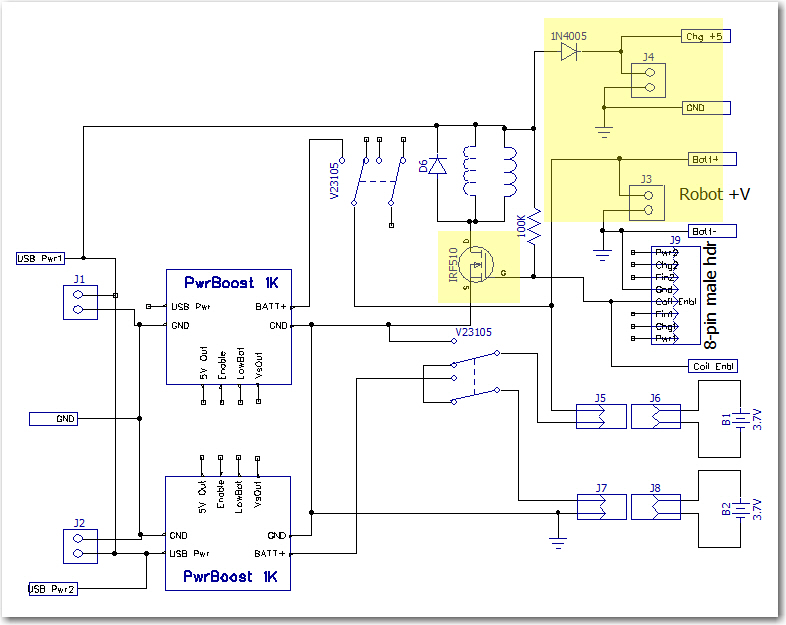
Dual Cell Charging Module with changes highlighted
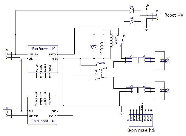
Dual cell balance charger. Note the two Axicom relays ganged to form the required 3PDT switch
As can be seen above, there are two major changes
- Added a IR510 n-channel enhancement mode MOSFET to control relay coil current via a new ‘Coil Enable’ signal rather than directly from the external +5V line. A 100K pullup was added so that the default configuration of the MOSFET switch was ‘ON’. A LOW signal on the ‘Coil Enbl’ line will switch the MOSFET to ‘OFF’, thereby switching the 3.7V cells from ‘charge’ (parallel) to ‘run’ (serial) mode.
- Removed the blocking diode from the +7.4V ‘Robot +V’ line, and added a separate ‘Chg +5’ 2-pin terminal with a blocking diode.
The idea was to set up an experiment where I could simulate the process of connecting the robot to the charger (thereby switching the