Posted 03/07/16
In my last post on this subject, I described my efforts to renew my acquaintance with CK Devices’ Mongoose 9DOF IMU board, with the intent of integrating it into my wall-following robot project. This post describes the first step toward that integration goal.
The Mongoose board operates on 3.3V and communicates via RS-232 protocol over a 6-pin 0.1″ header block, compatible with the CK Devices ‘FTDI Pro’ programmer module, as shown in the following photo.
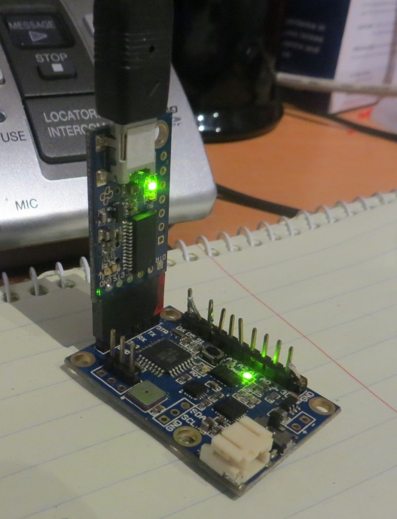
Mongoose 9DOF IMU board, with FTDI Pro USB-Serial adapter
Integrating this board into Wall-E requires addressing two distinct but related issues – the voltage difference between the 5V Arduino Mega controller and the 3.3V Mongoose, and the coding changes required to retrieve the desired heading/attitude information from the Mongoose.
The Hardware
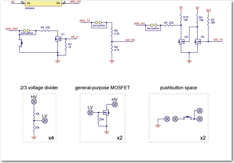
The 5V/3.3V issue requires that 5V serial data levels from the Arduino Mega be stepped down to 3.3V, and 3.3V serial data levels from the Mongoose be stepped up to 5V. Simply ignoring these problems does seem to work (the 5V data from the Mega doesn’t appear to harm the Mongoose, and the 3.3V data from the Mongoose does seem to be recognized by the Mega), but it is inelegant to say the least. Also, a recent addition to Wall-E’s superpowers included Pololu’s ‘Wixel Shield’ module, which fortuitously included some spare circuitry for just this purpose, as shown in the schematic drawing excerpt below. The upper right corner shows the full step-up circuit used to connect the 3.3V Wixel Tx line to the 5V Arduino Rx line, and the top center shows the step-down circuit used to connect the 5V Arduiono Tx line to the 3.3V Wixel Rx line. The lower area shows the spare parts available on the Wixel shield – and the important thing is that there are two general-purpose N-channel MOSFETs. These can be used to construct the same step-up circuit to connect the 3.3V Mongoose Tx line to the 5V Arduino Mega Rx1 line, and one of the 4 available 2/3 voltage dividers can be used to step down the 5V Arduino Mega Tx line to the 3.3V Mongoose Rx line.
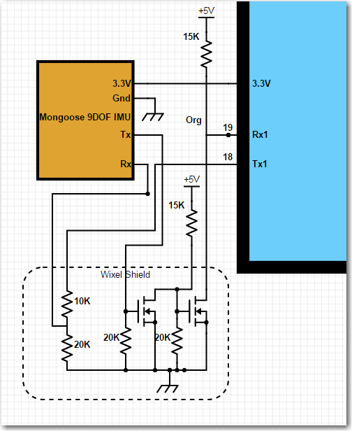
The following image is a small section of my overall Scheme-it (Digikey’s free online schematic capture app) schematic for Wall-E, showing the addition of the Mongoose IMU.
The photo below shows the serial up/down converter connections on the Wixel Shield board. On the near side, Red = Mongoose Rx, Org = Mongoose Tx. On the far side, Org = Mega Rx1, White = Mega Tx1.
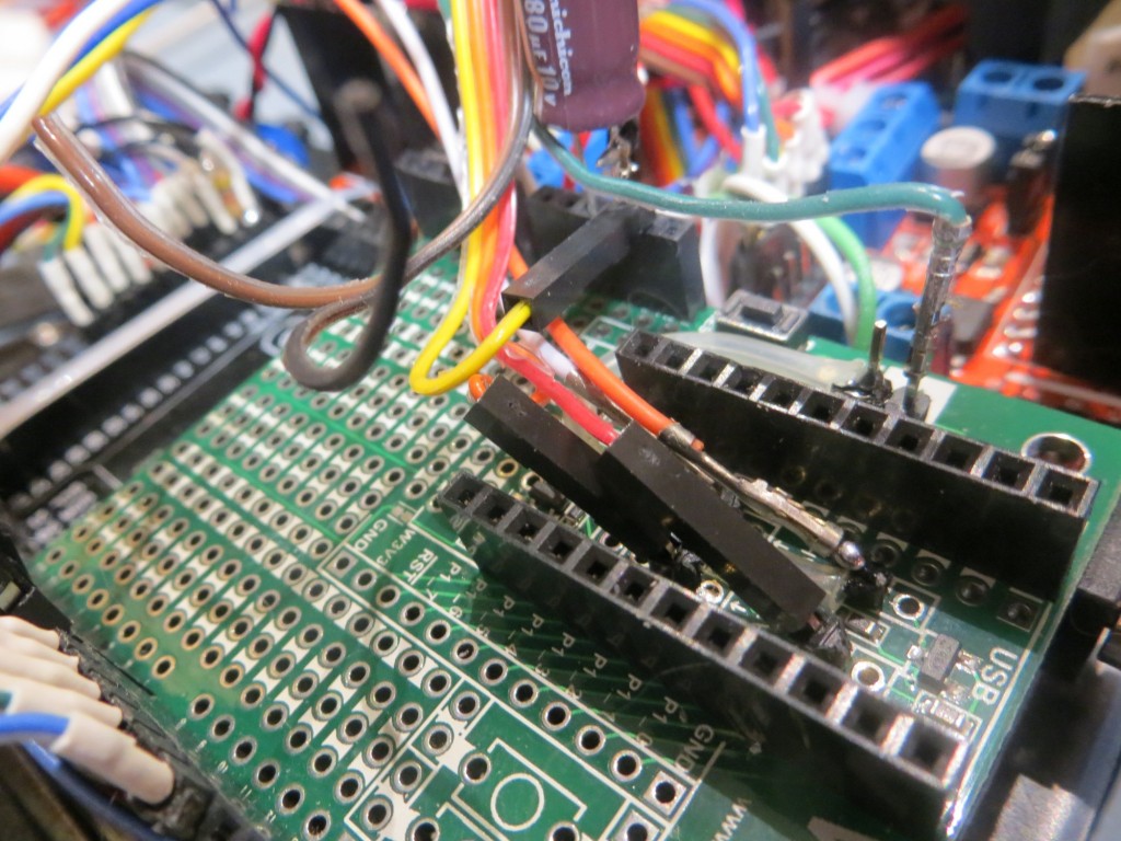
Mongoose Serial Up/Down Converter Connections. Near side Red = Mongoose Tx, Org = Mongoose Rx. Far side: Org = Mega Rx1, White = Mega Tx1. Yel = Mongoose 3.3V, Grn = Mongoose Gnd.
The Software:
After getting the hardware wired up and tested, I naturally thought All I had to do was plug in the Mongoose with the full set of reporting software, and I’d be ready to go – NOT! So, after the obligatory yelling and cursing and the appropriate number of random code changes hoping something would work, I was forced to fall back on my somewhat rusty (but not completely worthless) trouble-shooting skills. I started by creating a new, blank Arduino project. Into this project I placed code to simply echo whatever I typed on the serial command line to the serial view window. To this I added a few lines to make the laser pointer blink on/off, just to provide a visual “I’m alive!” indication, and then tested it. After all errors were made/corrected, etc, the final code was as shown below.
|
1 2 3 4 5 6 7 8 9 10 11 12 13 14 15 16 17 18 19 20 21 22 23 24 25 26 27 28 29 30 31 32 33 34 35 36 37 |
//Laser pointer const int RED_LASER_DIODE_PIN = 7; long lastmillisec = 0; bool stringComplete = false; String inString = ""; void setup() { Serial.begin(115200); //Laser pointer pinMode(RED_LASER_DIODE_PIN, OUTPUT); } void loop() { digitalWrite(RED_LASER_DIODE_PIN, HIGH); //fire the laser pointer delay(20); digitalWrite(RED_LASER_DIODE_PIN, LOW); delay(50); //03/06/16 serial coms test routines using just the default serial port if (Serial.available() > 0) { Serial.print(Serial.available()); Serial.print(" "); char inByte = Serial.read(); Serial.print(inByte); } } |
asd;lfkjsaf;
al;skfdj
The next step was to extend the echo loop to include Serial1, with a simple jumper between Tx1 and Rx1 on the Mega board. In the software all this required was Serial1.begin(9600) in Setup() and the addition of the code to route command line bytes out Tx1 and to route received bytes on Rx1 to Tx0 so that it would get displayed on the serial monitor. The code to do this is shown below:
|
1 2 3 4 5 6 7 8 9 10 11 12 13 14 15 16 17 18 19 20 21 22 23 24 25 26 27 28 29 30 31 32 33 34 35 36 37 38 39 40 41 42 43 44 |
//Laser pointer const int RED_LASER_DIODE_PIN = 7; long lastmillisec = 0; bool stringComplete = false; String inString = ""; void setup() { Serial.begin(115200); Serial1.begin(9600); //Laser pointer pinMode(RED_LASER_DIODE_PIN, OUTPUT); } void loop() { digitalWrite(RED_LASER_DIODE_PIN, HIGH); //fire the laser pointer delay(20); digitalWrite(RED_LASER_DIODE_PIN, LOW); delay(50); //03/06/16 serial coms test routines using just the default serial port if (Serial.available() > 0) { Serial.print(Serial.available()); Serial.print(" "); char inByte = Serial.read(); Serial1.print(inByte); //ship off to Tx1 } //this echo routine works fine while (Serial1.available() > 0) { char readbyte = Serial1.read(); Serial.print(readbyte); } } |
The next step was to extend the loop beyond Serial1 and into the Mongoose, by replacing the jumper from Tx1 to Rx1 with the Mongoose board’s Rx & Tx lines respectively, and replacing the normal Mongoose code with the turn-around (echo) code. No change should be required to the Arduino code, as it will still be echoing whatever shows up at Rx1 to Tx0.
The Mongoose code is:
|
1 2 3 4 5 6 7 8 9 10 11 12 13 14 15 16 17 18 19 |
void setup() { Serial.begin(9600); } void loop() { /* add main program code here */ while (Serial.available() > 0) { char readbyte = Serial.read(); Serial.write(readbyte); } } |
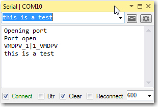
When this code was loaded into the Mongoose and run stand-alone, I got the following output by typing ‘this is a test’ on the serial port command line.
After the Mongoose was disconnected and placed into the robot circuit, I got the following output from the Robot project on a different comm port.
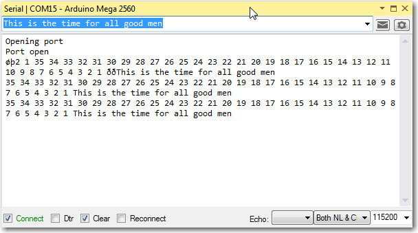
So, it is clear from the above that the Mongoose board connected (through the step-up/down circuitry on the Wixel shield) to Rx1/Tx1 is successfully receiving and echoing whatever shows up on its serial port.
Now it was time to reload my modified version of CK Devices ‘Mongoose_base’ firmware back onto the Mongoose and get it running with Wall-E’s firmware. After the usual number of hiccups and such, I got it running and nicely reporting ‘Tilt’ (X-axis accelerometer) and ‘Heading’ (derived from 3-axis magnetometer values) along with the normal robot telemetry values, as shown in the printout below.
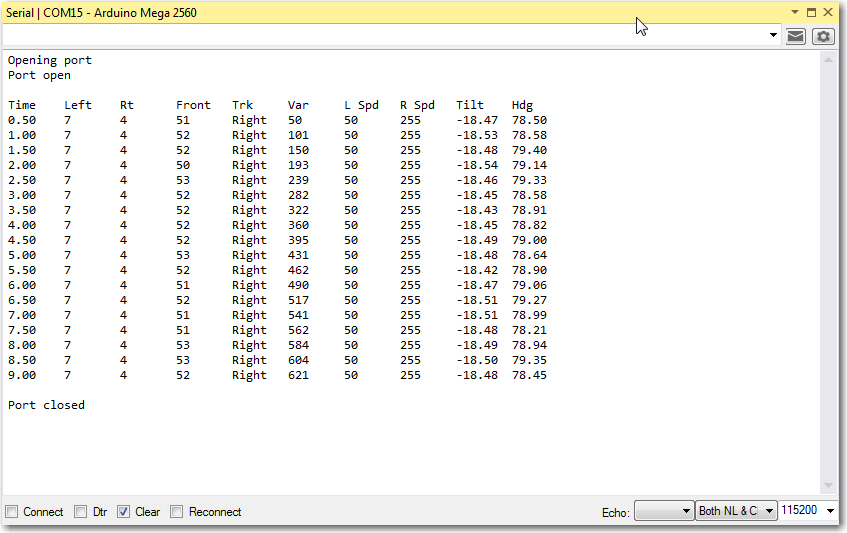
Final version showing Mongoose Tilt & Hdg values integrated into normal robot telemetry
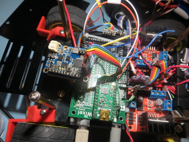
Although the Mongoose module has been successfully integrated into the robot system from a technical standpoint, there is still plenty of work to be done to complete the project. At the moment (see the photo below), it is just kind of ‘hanging around’ (literally), so some additional work will be required to mount it properly. Stay tuned! ;-).

Mongoose installed loosely on Wall-E2
Pingback: Giving Wall-E2 A Sense of Direction – Part III - Paynter's Palace