Posted 11/19/2015
A week or so ago I posted an account of my attempt to add a glass plate to my Printrbot Simple Metal print bed. I thought I had a great idea – place patches of copper foil tape on top of the glass plate at the three points where the Z-axis probe sensor checks for print bed tilt (it’s called auto-leveling, but it is actually more like auto-tilt correction), and everything should be groovy. Unfortunately, what I thought would happen and what actually happened were two different things. It appeared that either tilt correction wasn’t being applied at all, or it was being applied, but in the wrong direction (which doesn’t make any sense either, because I didn’t change anything except adding the glass plate).
So, I decided to make another run at the problem. My new approach was three-fold; first, I took some time to thoroughly investigate the flatness of the original Printrbot print bed, and the flatness of the glass plate. Second, I decided to cover the entire glass plate with copper foil, not just the small areas used by the Z-axis sensor. Third, I figured out a way (the ‘G30’ command) to take Z-axis sensor reading at multiple spots on the print plate, rather than just the 3 points used in normal printing, so I could really determine how well the Z-axis sensor itself behaved.
Printrbot print bed and glass plate flatness investigation:
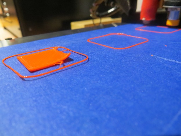
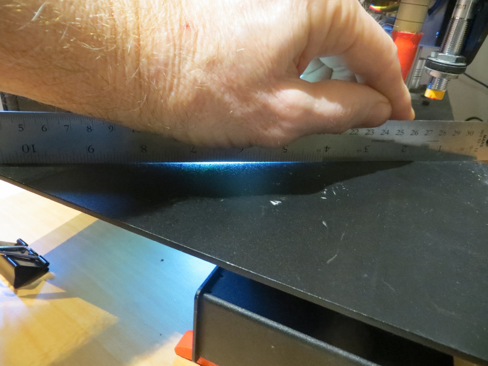
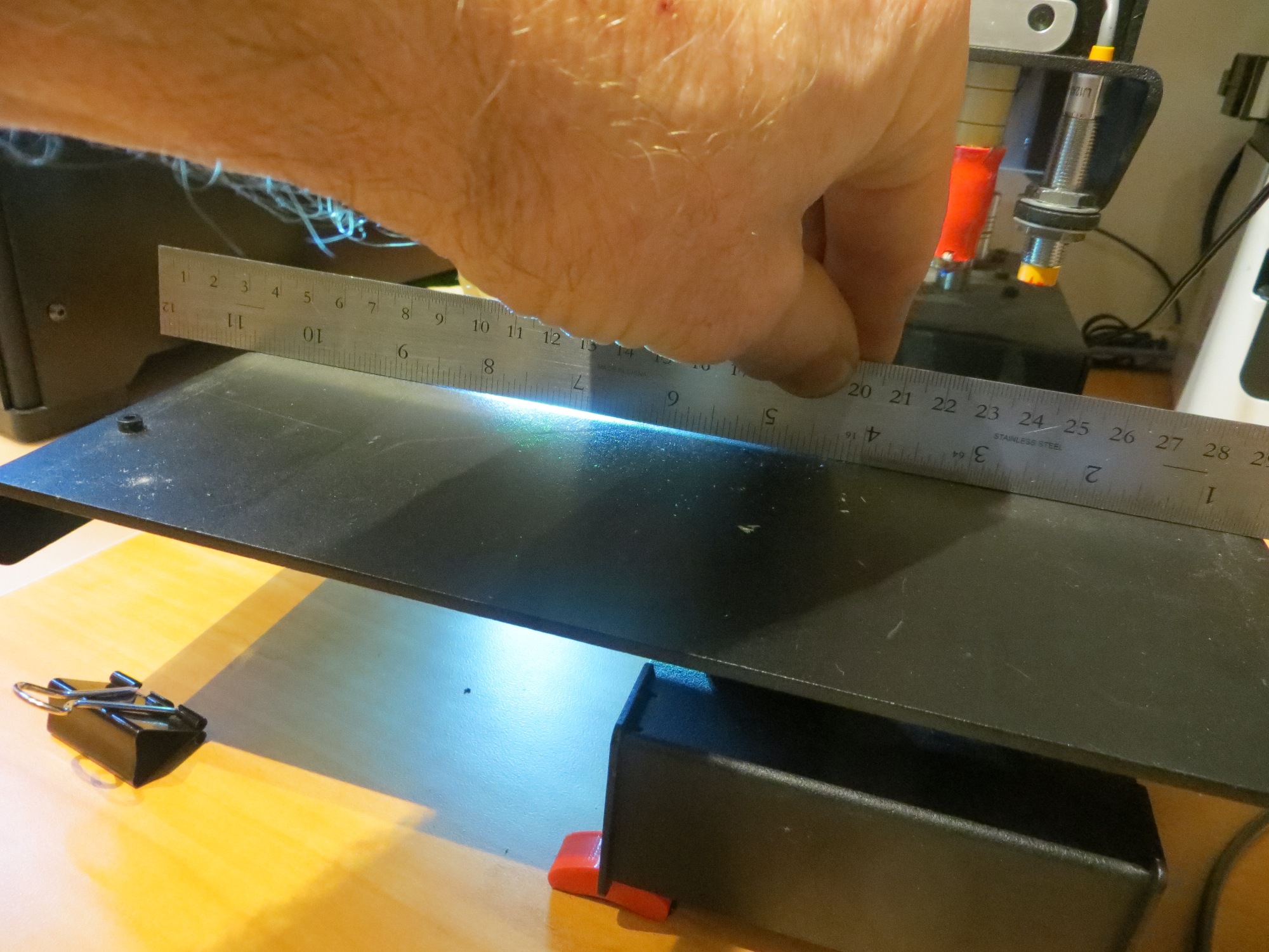
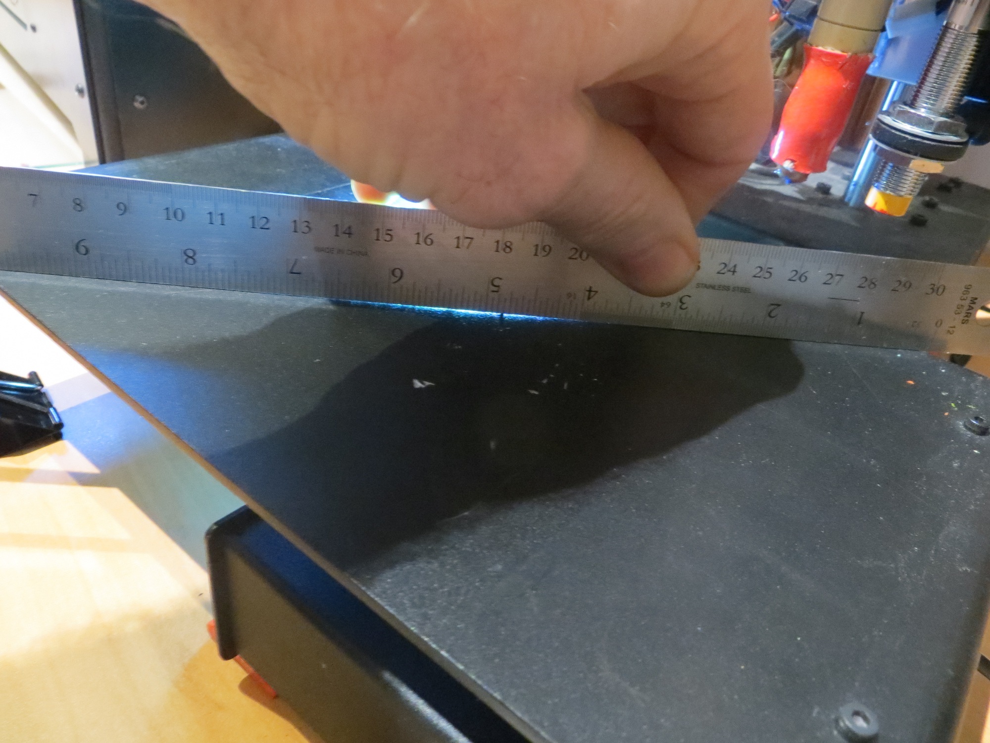
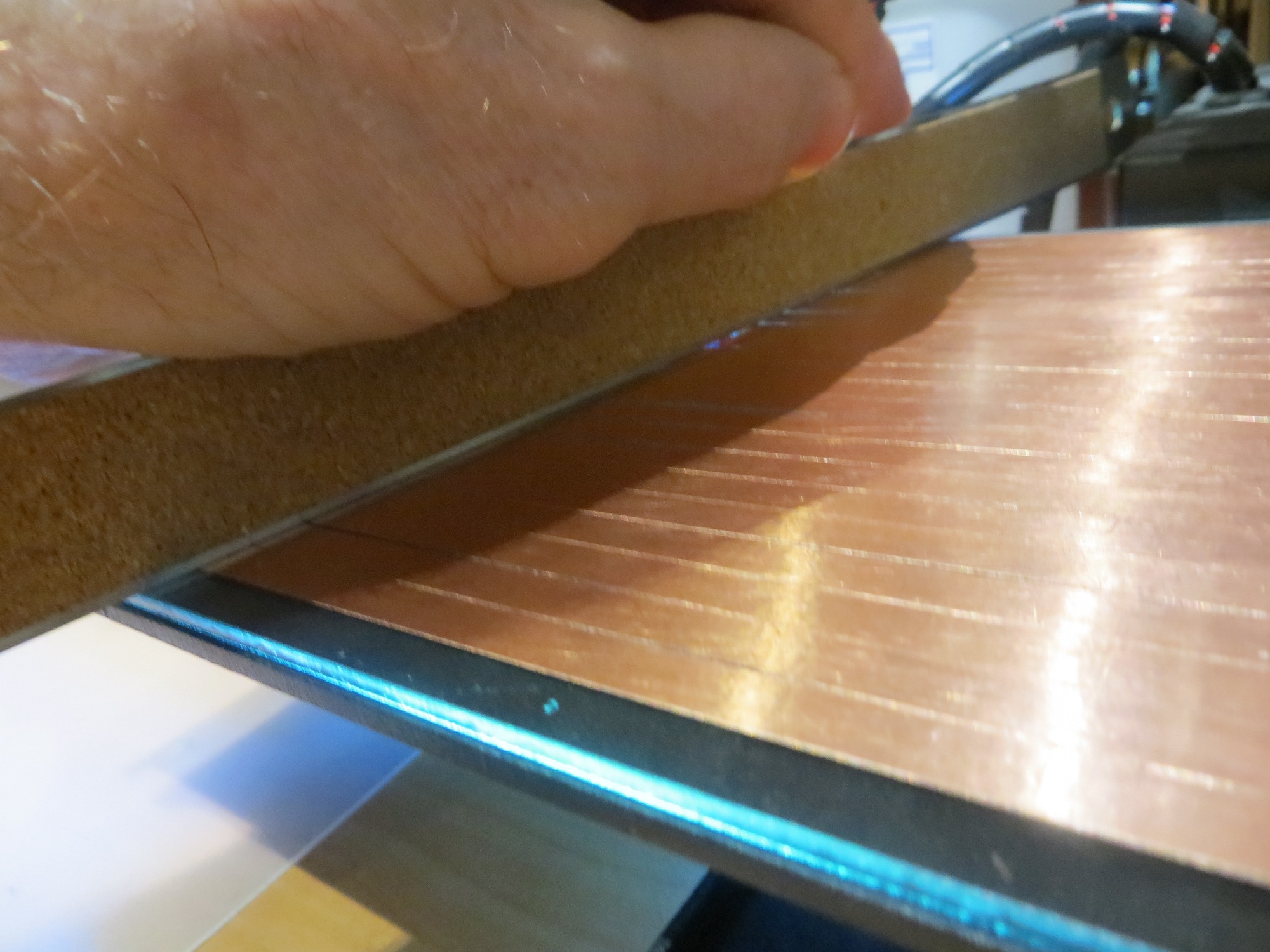
I used two different techniques to evaluate the flatness of both the original Printerbot print bed and the glass plate addition. The first technique was to place a light source so that it illuminated the bed from the side, and look for light leakage under a straight-edge placed on the bed. The second technique was to use a piece of printer paper (approx 0.09 mm thickness) to see if there were any areas where the paper would slide freely under the straight edge. The photos below show the result for both the original print bed and the glass plate. The first image shows the setup, with an LED flashlight placed so it shines light parallel to the surface, with a steel straight-edge blocking the beam except where the bed is warped. Subsequent photos show warped areas.
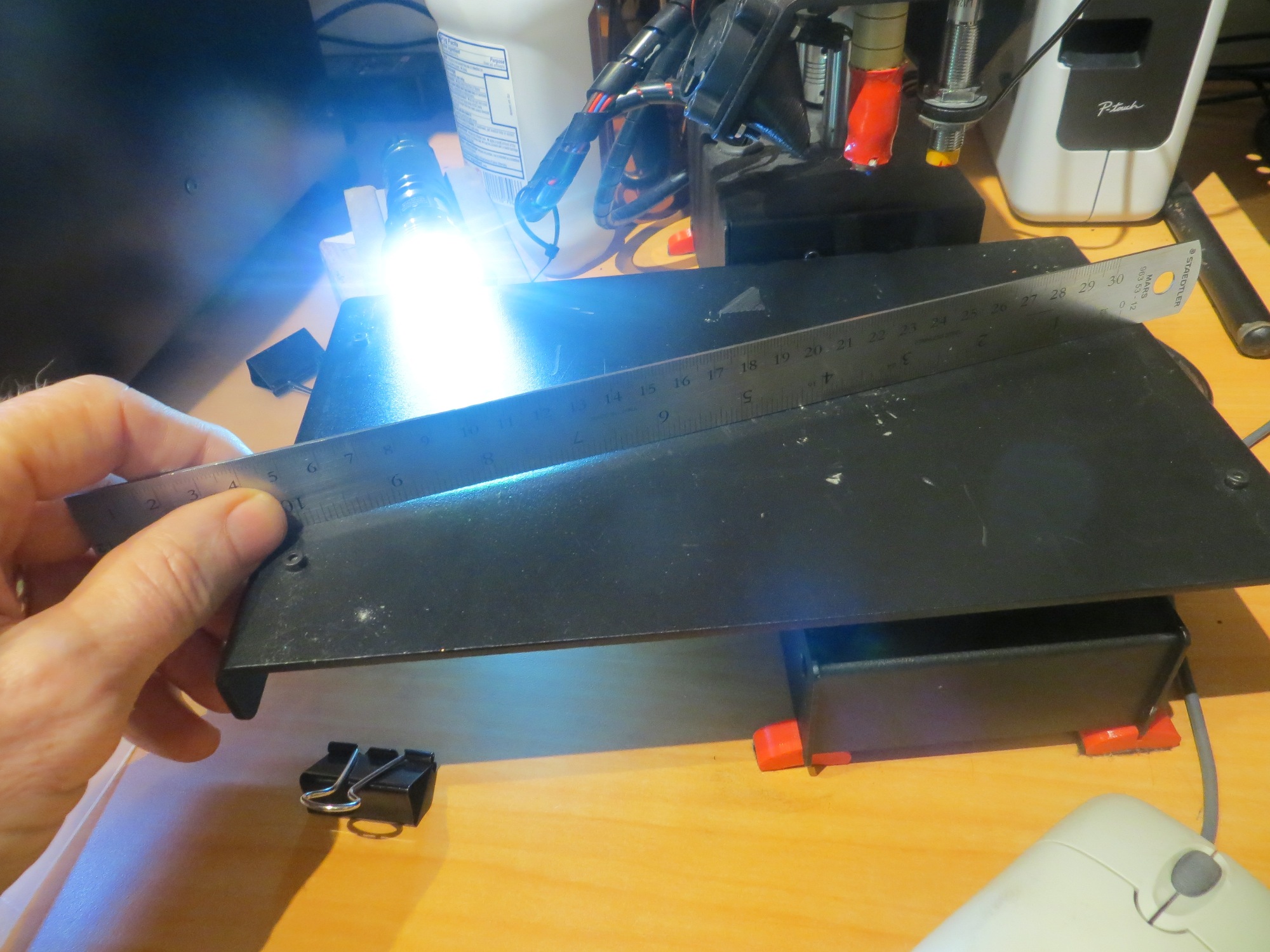
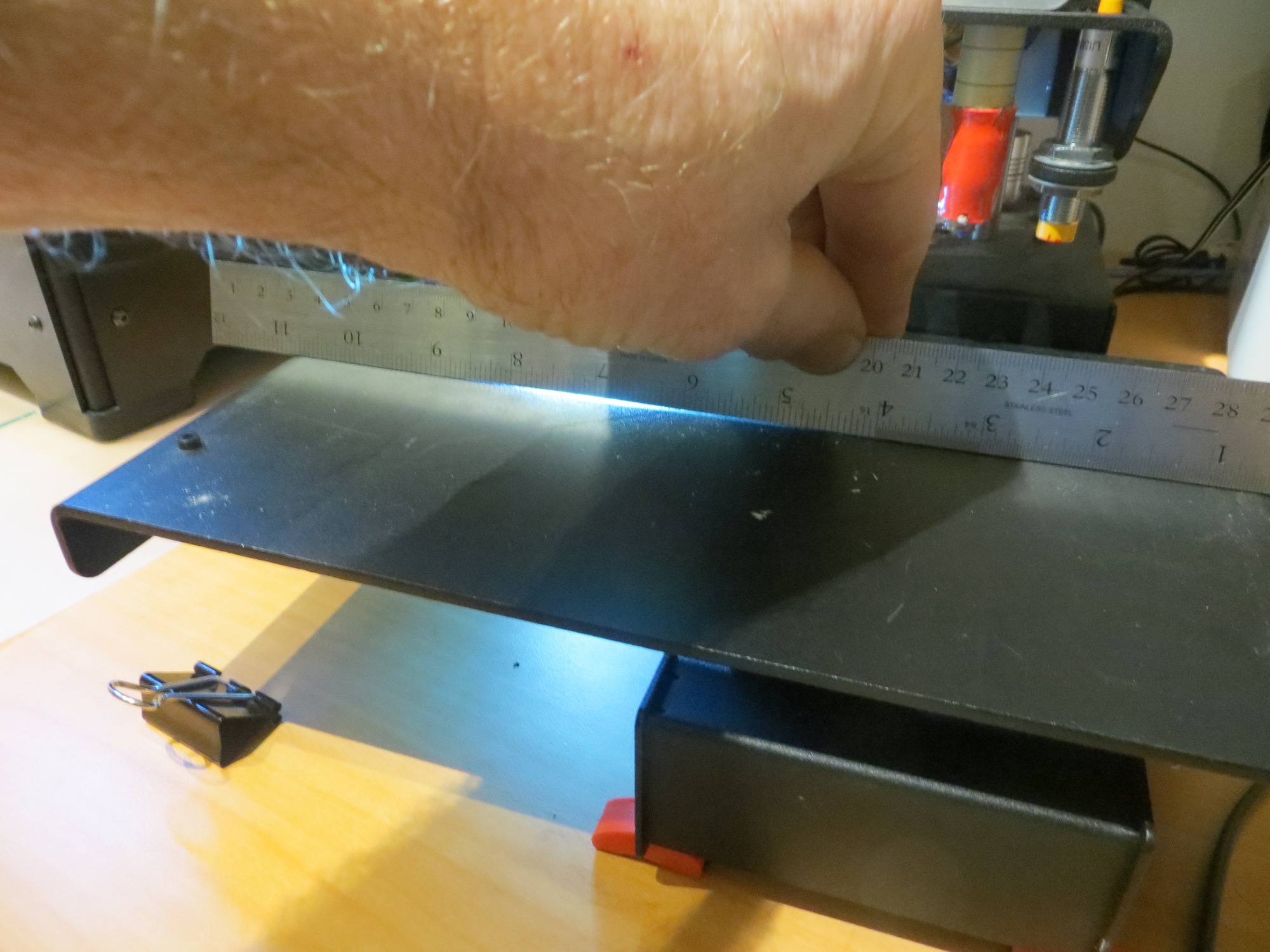
Flashlight shining along surface of print bed, with steel straight-edge blocking light except where the bed is warped.
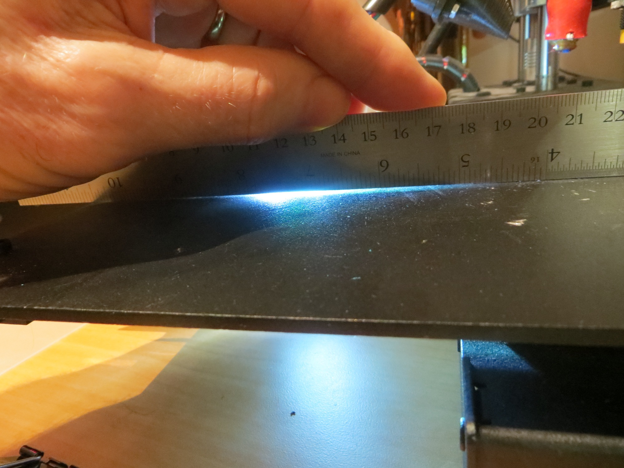
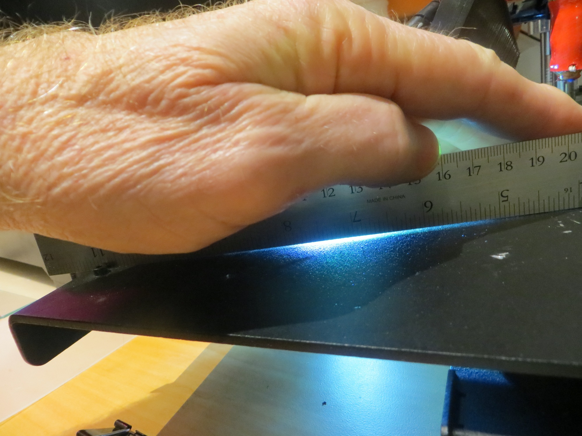
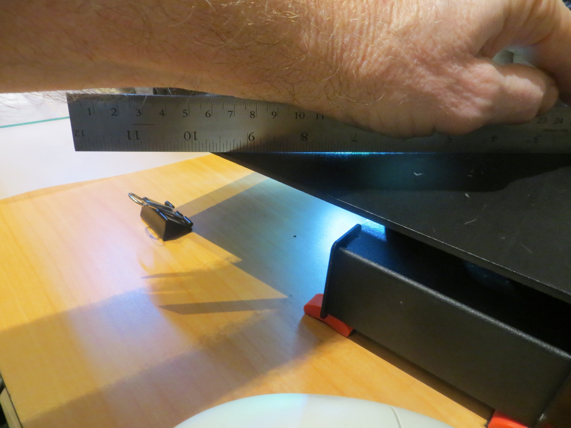
Next I did the same thing with the glass plate, as shown in the following images.
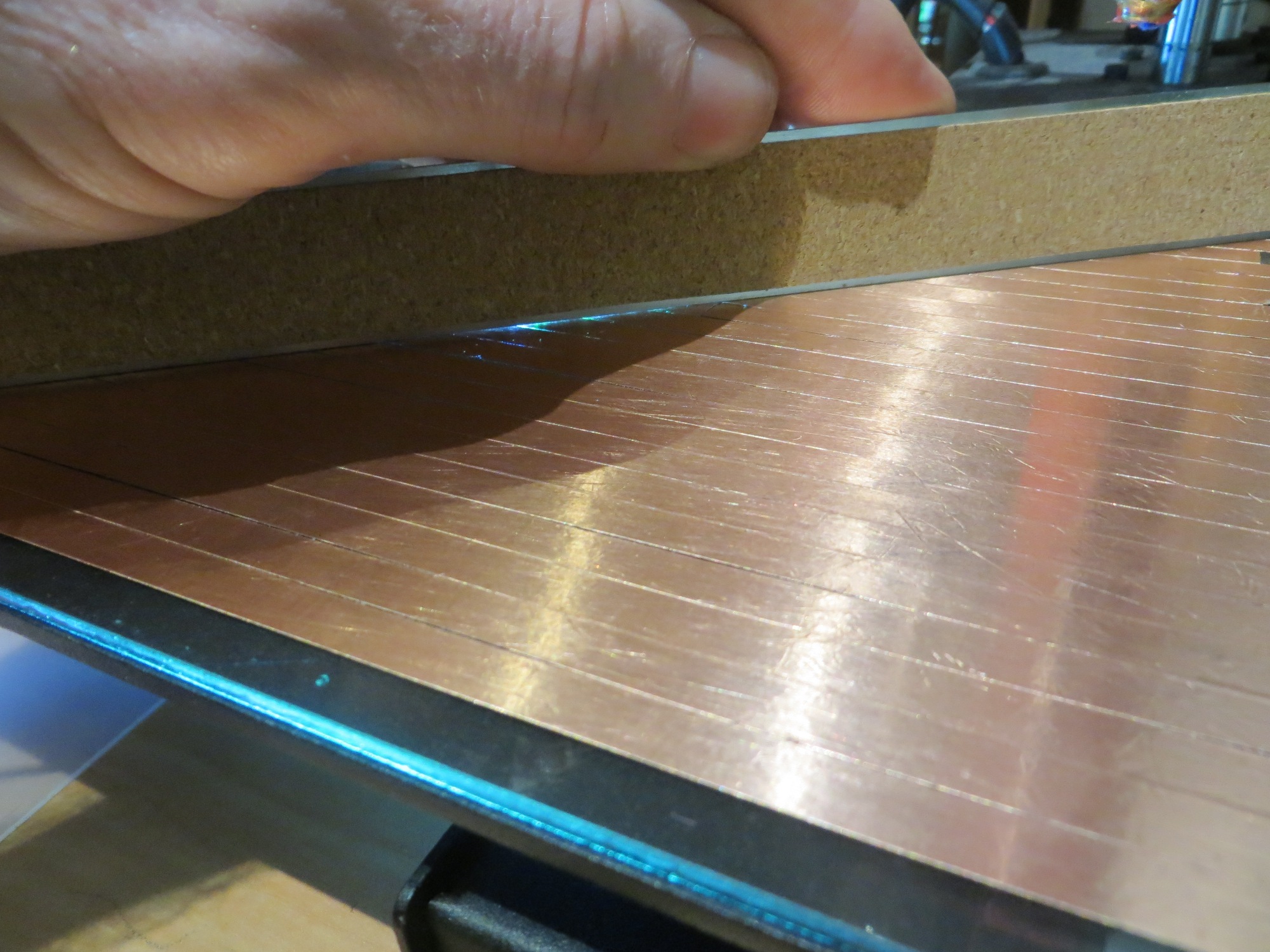
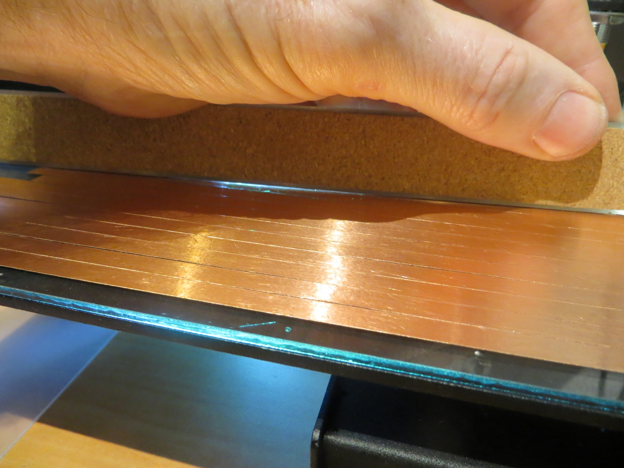
The glass plate is clearly much flatter than the original print bed. I verified this using the paper technique – I was able to easily slide a piece of 0.09 mm paper under the straight-edge on the original print bed, but not on the glass plate. So, as far as flatness is concerned, the glass plate is a clear winner.
Z-Axis Probe Measurements
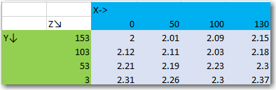
Since I was now convinced that the glass plate was much flatter than the original print bed, this issue could not be the reason I was having so much trouble trying to get reliable prints at different points on the print bed. So, I turned my attention to the only other possible factor, the Z-axis probe itself. If it was somehow producing aberrant readings, maybe that would explain why the Z-axis offset required for printing at the near right corner was wildly inappropriate for the same print in the back left corner. To acquire the data I made use of the G-code ‘G30’ command, which causes a Z-axis probe operation at the current X/Y location. I recorded Z-axis probe readings at 12 locations on the glass plate, and plotted the results using Excel’s ‘Surface’ plot feature
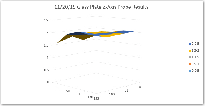
Z-axis probe sensor readings for glass plate
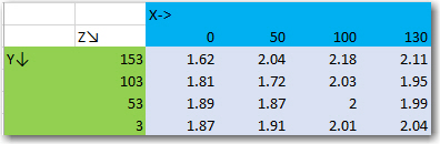
11/20/15 Glass Plate Z-axis probe sensor results
As can be seen in both the data and the surface plot, the glass plate is pretty flat – with only a 0.42 mm deviation from one extreme from the other.
The same set of measurements were performed on the original Printrbot metal print bed, with the following results:
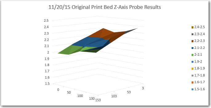
11/20/15 Original print bed Z-axis probe results
11/20/15 Original print bed Z-axis probe results
The data shows that the original print bed is pretty flat too, even though the illumination experiment showed that it exhibits significant warping. I suspect that the probe measurement locations were too widely spaced to capture the low spots. In any case, all that can be said for sure at this point is that both surfaces (original print bed and glass plate) are pretty flat, and both exhibit some tilt, with Z-axis probe measurements consistently rising from the left rear corner (0,153) to the front right corner (130,3).
Print Trials:
After convincing myself that the glass plate was indeed flat, and that any residual tilt should be well within the Printrbot’s correction range, I decided to do a series of test prints – starting at the rear left corner and moving toward the near right corner. For the first print, I adjusted the Z-offset for optimum printing – not too close, not too far away. Then I kept this same Z-offset for all the other prints. The following photos tell the story.
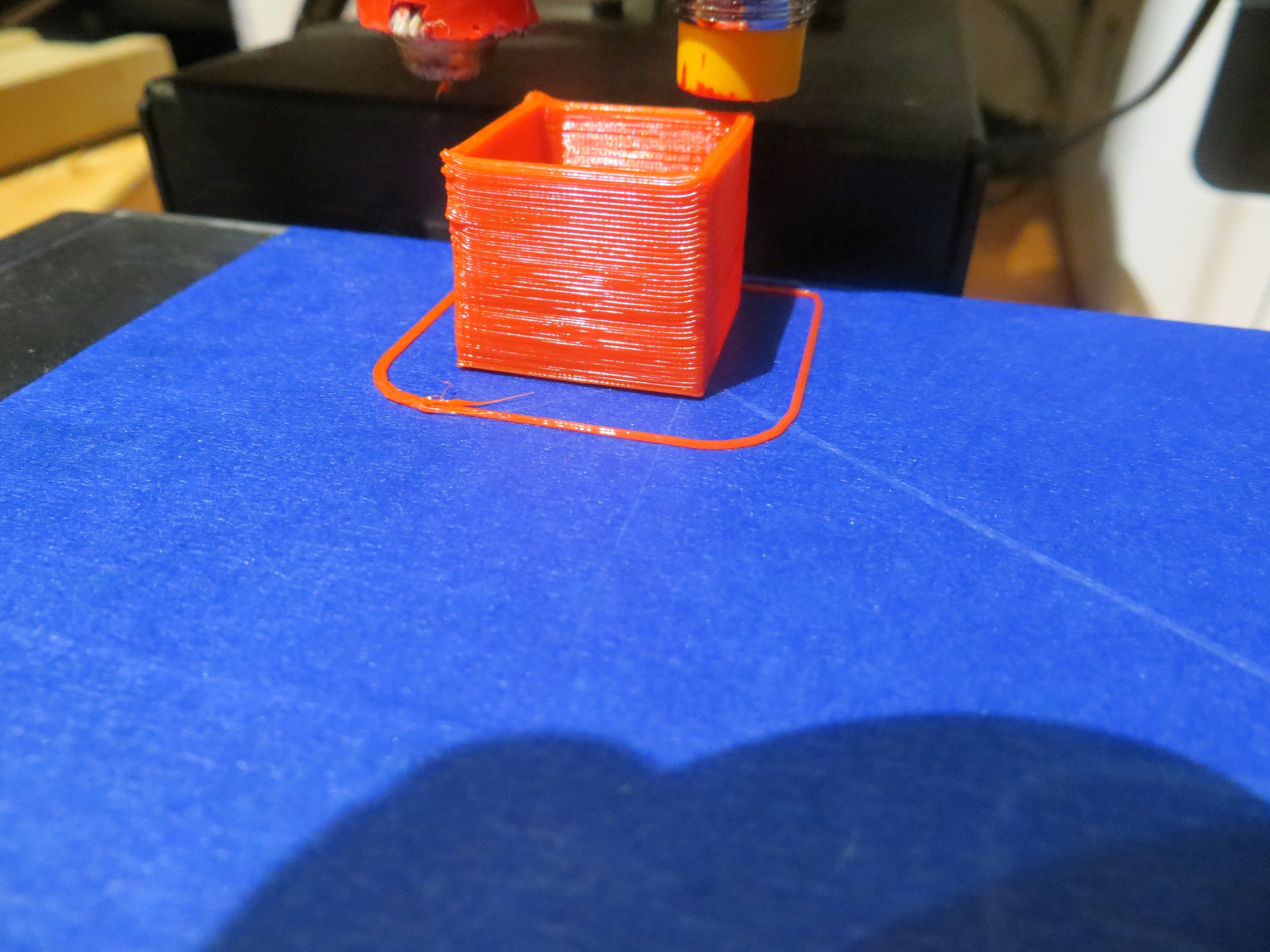
20mm cal cube printed at the rear left corner (0,153)
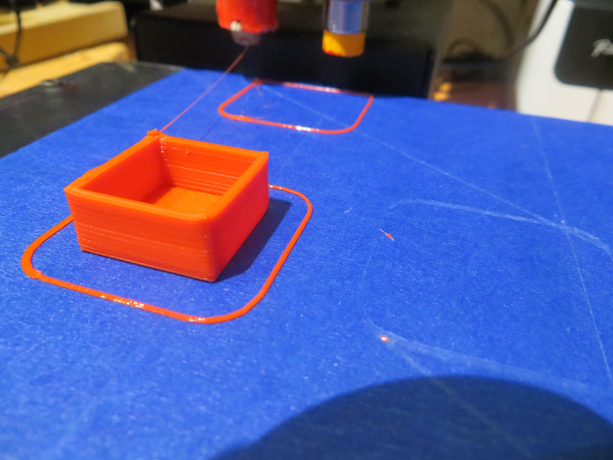
20mm cal cube printed at (0,103)
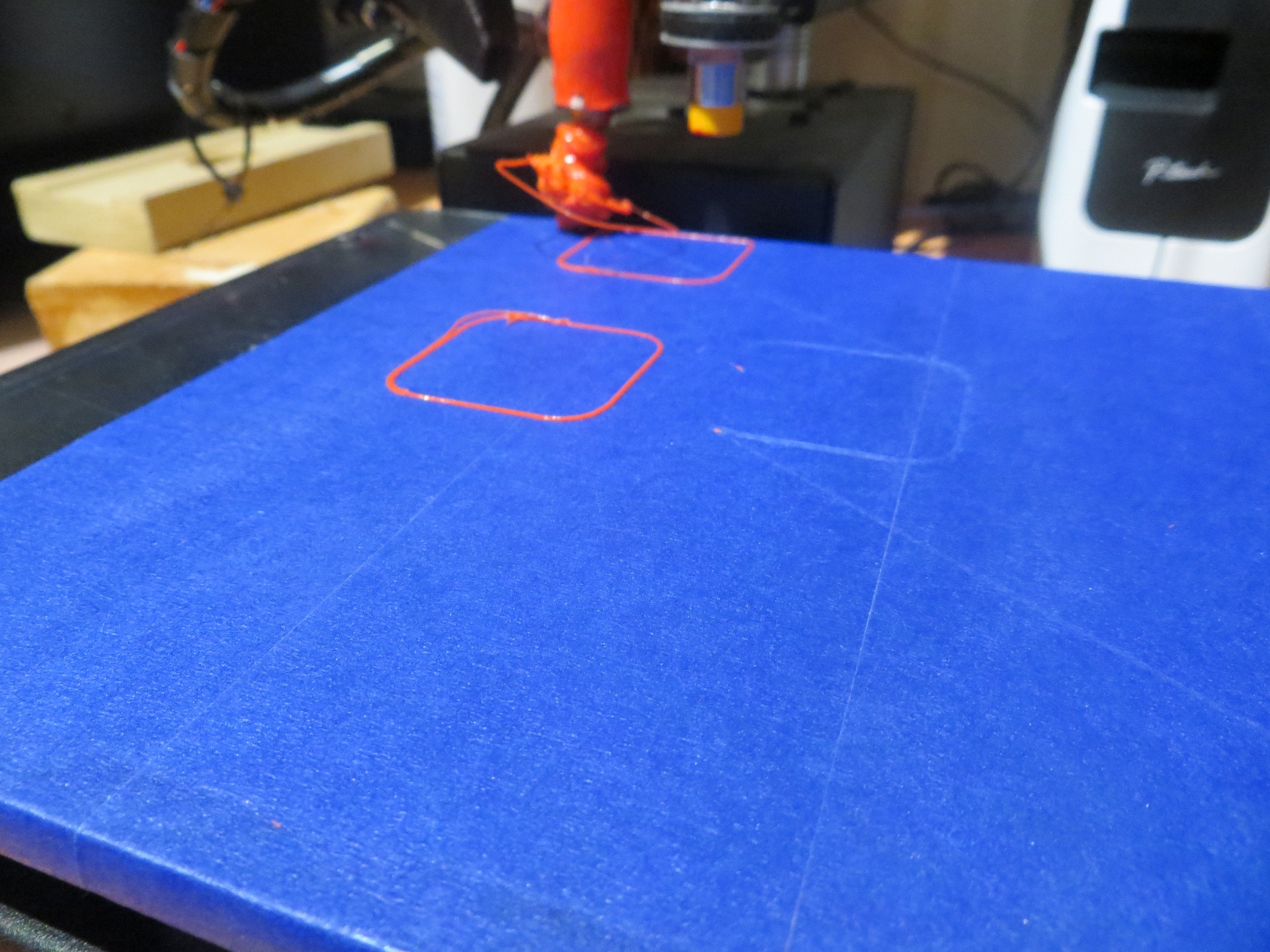
First try at printing 20mm cal cube at the third position (0,53). Note the blob attached to the extruder!

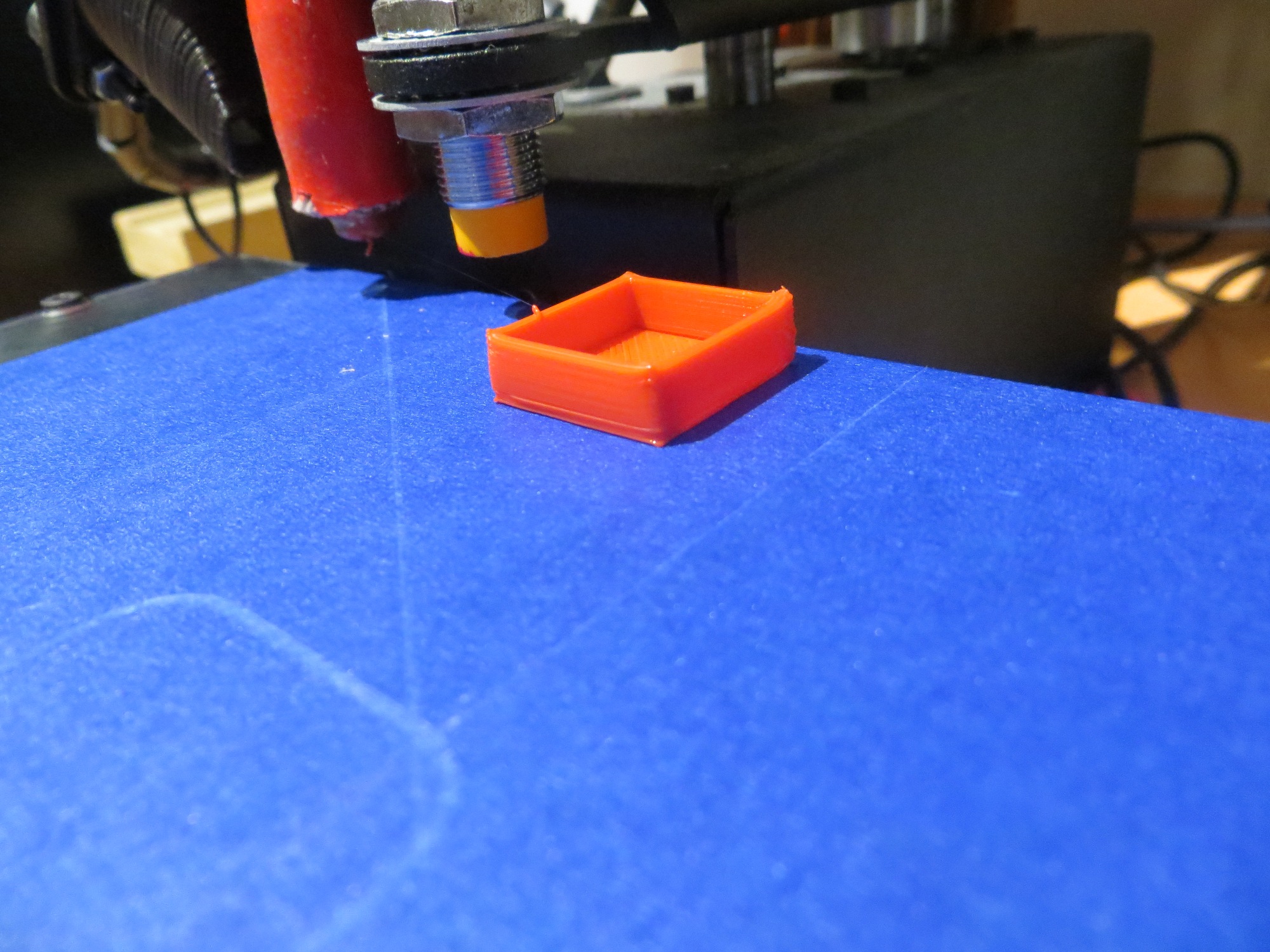
2nd try at printing 20mm cal cube at the third position (0,53). Note the raised corner
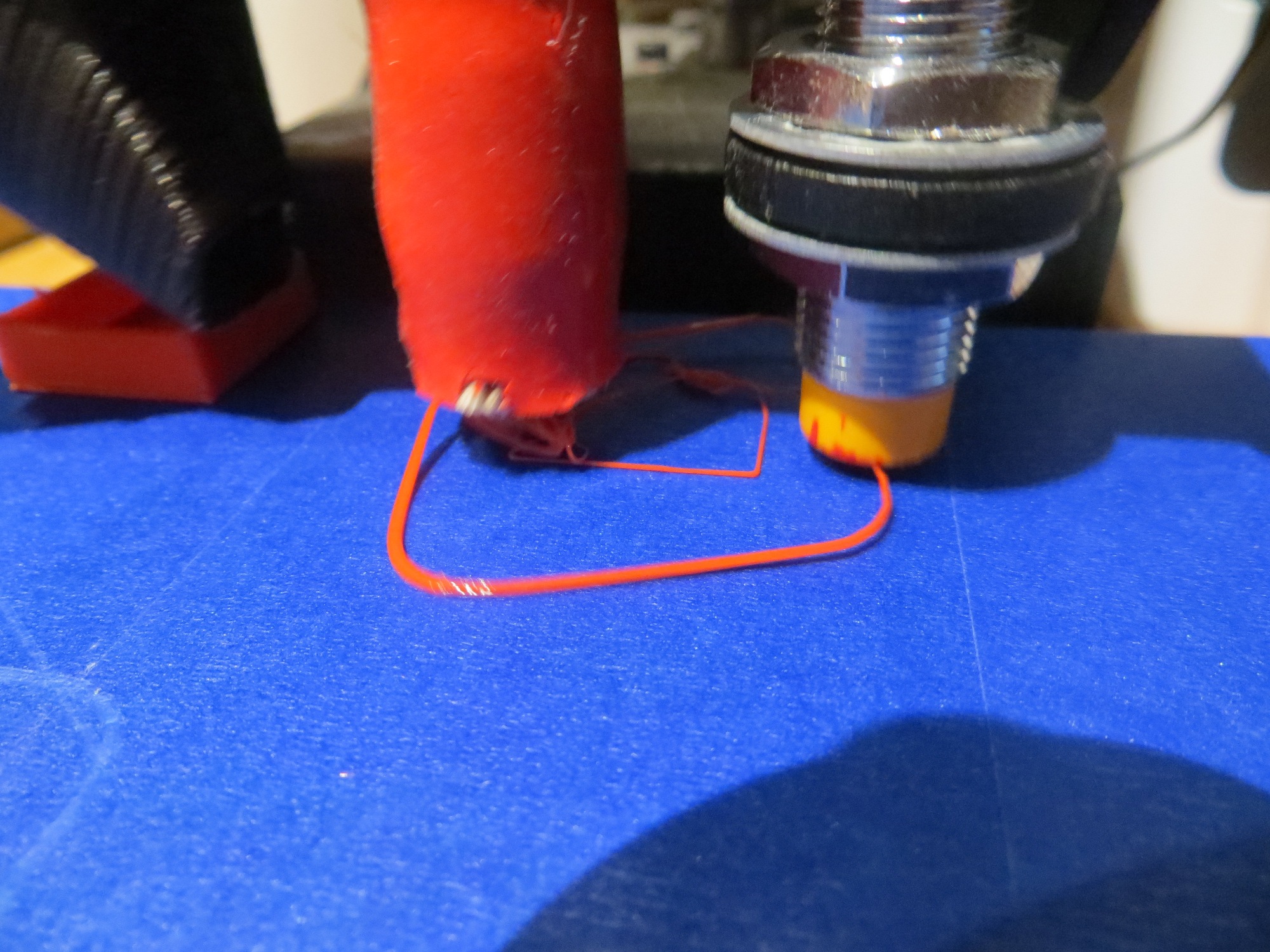
20mm cal cube printed attempt at the near right corner. Part is separated from the bed and ‘blobbed’ to extruder and
20mm cal cube printed at the rear edge, midway toward the right
20mm cal cube print attempt at the rear right corner. Part has separated from bed and is ‘blobbed’ to extruder.
So, at this point I’m pretty sure of three things:
- The glass plate print bed is pretty darned flat
- The Z-axis probe seems to be working correctly
- The Printrbot tilt correction feature does not appear to be working properly.
Stay tuned,
Frank