Posted 08/12/15
In my last post (http://gfpbridge.com/2015/08/wall-e-has-more-interrupt-issues/) I found that the Pulsed Light LIDAR-Lite (now called ‘V1’ as there is a new ‘Blue Label’ V2 version out) couldn’t keep up with the pace of hardware interrupts from my 10-tooth tach wheel running at about 120 RPM. So, I decided to try my luck with the I2C interface, as that was rumored to be somewhat faster than the MODE line interface. I had resisted doing this as it requires the use of the I2C (or ‘Wire’) library, and I thought it would be more trouble to implement. As it turned out, I was mostly wrong (again) :-).
In any case, changing over from the MODE interface to the I2C interface turned out to be a non-issue. Pulsed Light has some nice Arduino example code on GitHub, along with clear instructions on what I2C library to use (there are several). I did have to swap out the MODE line for one of the two I2C lines due to the limitation of 6 wires through the spinning LIDAR slip-ring setup (4 were already occupied by power, ground, and the two laser diode wires). However there was some good news in that this freed up one of the Uno’s analog ports, as the I2C SCL and SDA lines have dedicated pin-outs on the Uno.
Anyway, I got the SCL/SDA lines connected through the slip-ring and to the Uno, downloaded/installed the necessary I2C library, downloaded and installed the Arduino example, code, and uploaded it to my Uno system. Sure enough, the example code worked great, and in addition gave much more accurate distance results than with the MODE method (with the MODE method, I had to subtract 40 cm from each measurement. With the I2C method, the measurements seemed to be ‘dead on’).
However, when I instrumented the code to toggle a Uno digital pin so I could measure the timing with my trusty O’Scope, I received a major shock. Instead of the 30-35 msec cycle time from the MODE method, the I2C method was showing more like 110-120 msec – MUCH slower than the MODE method, and WAY too slow for servicing interrupts at 20-25 msec intervals!
Yikes – what to do? Well, as usual when I’m faced with a situation I don’t understand, my response is to yell for help, and take more data. the ‘yell for help’ part was accomplished via an email to ‘help@pulsedlight3d.com’, and the ‘take more data’ part is described below.
The first thing I did was to re-download the Pulsed-Light test code from GitHub and run it again without any modifications. The test program simply writes distances out to the PC console, and I was able to re-verify that the LIDAR unit was indeed responding with what appeared to be correct distances, and responded appropriately when I waved my hand in front of the optics.
Next, I added a line of code at the top of the test code’s Loop() section to force the Uno’s LED pin (pin 13) HIGH, and another one at the ‘bottom’ (after the measurement but before the Serial.println() statement) to force the LED pin LOW. This gives me the ability to directly view the measurement timing on my trusty O’Scope. The reason the LOW statement line has to be before the Serial.println() statement is that the bottom of the Loop() code and the top are actually the same point in time, which would effectively put the HIGH and LOW statements right next to each other, making O’Scope measurements impossible. By putting the LOW statement before the Serial.println() statement, I am guaranteed to have a LOW period equal to the time it takes the Serial.println() statement to convert the distance value to a string and send it to the serial port.
After uploading the above modification to the Uno, I got the following Scope screenshots:
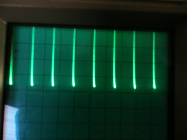
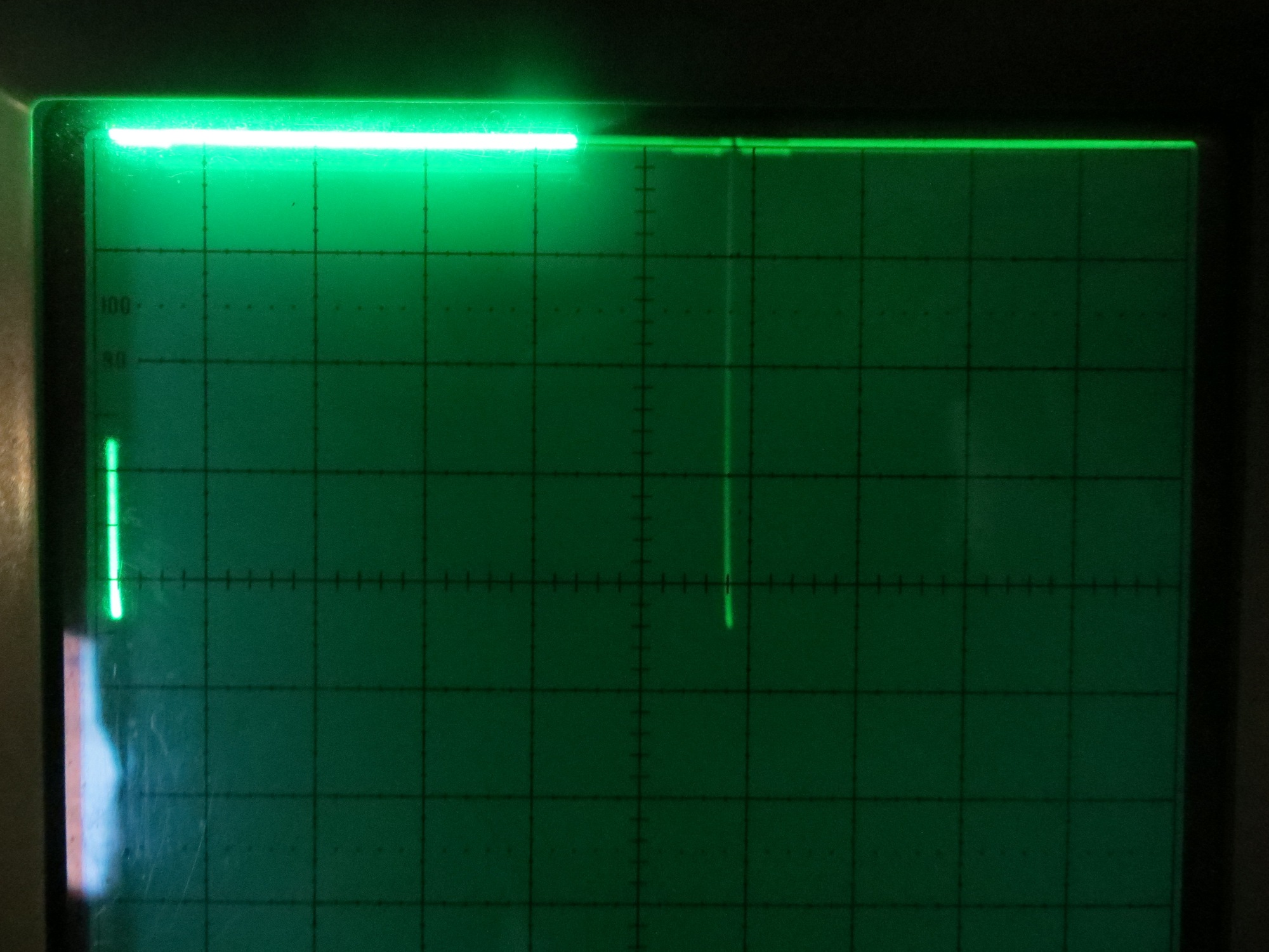
20msec/div showing the ’20msec’ mode.
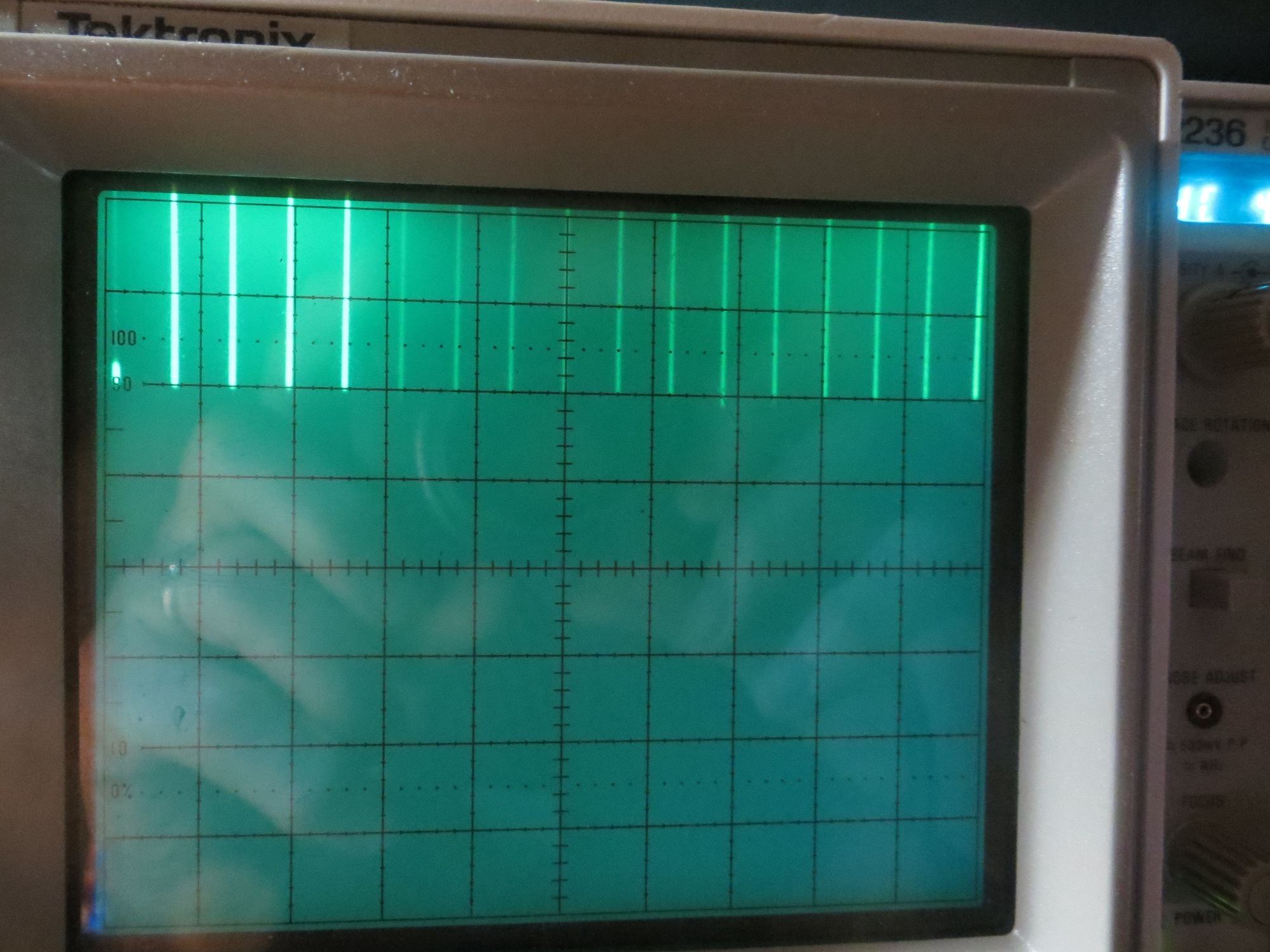
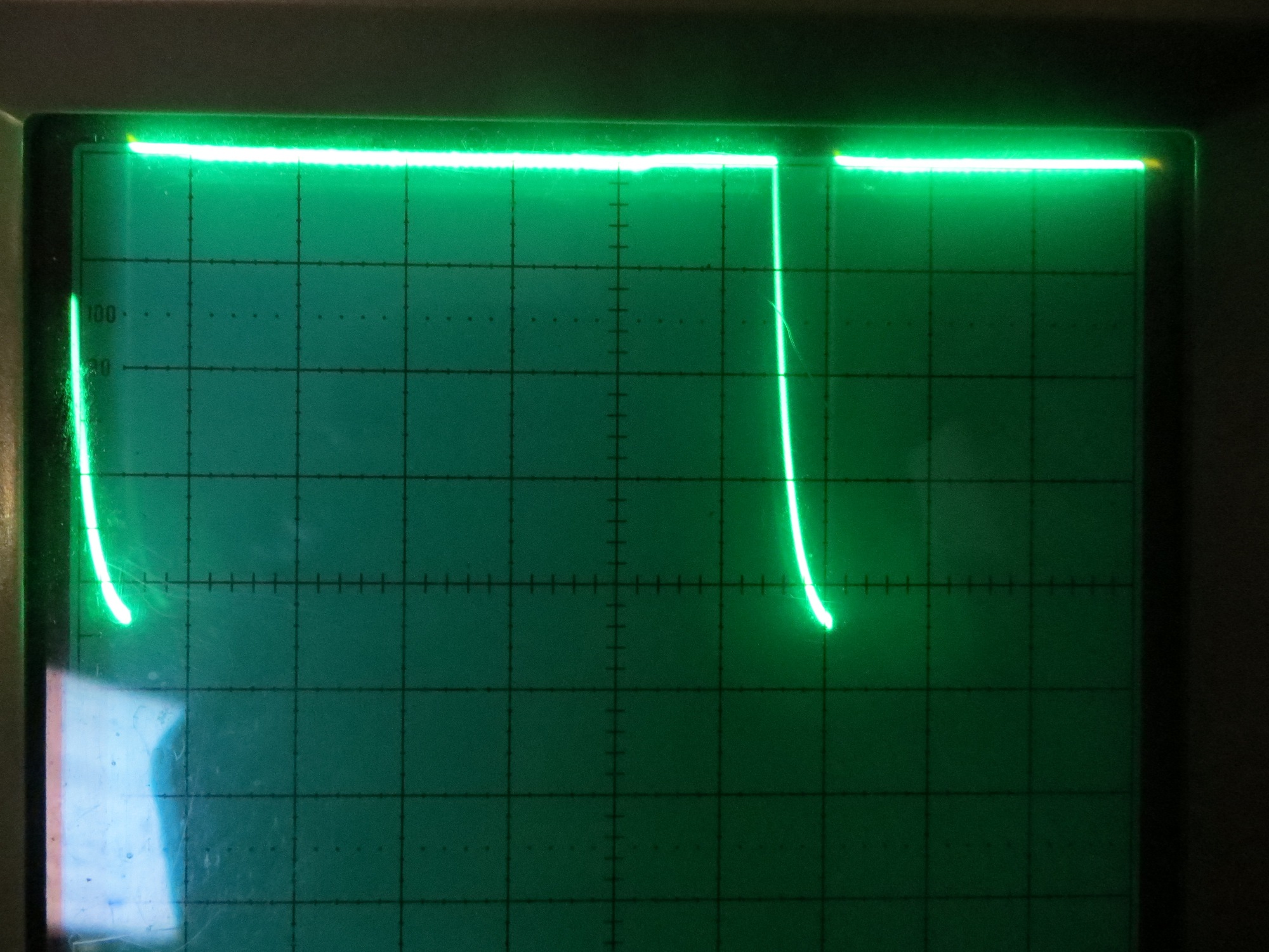
20msec/div showing the ‘100msec’ mode, where the LOW between measurement pulses are spaced approximately 100 msec apart.
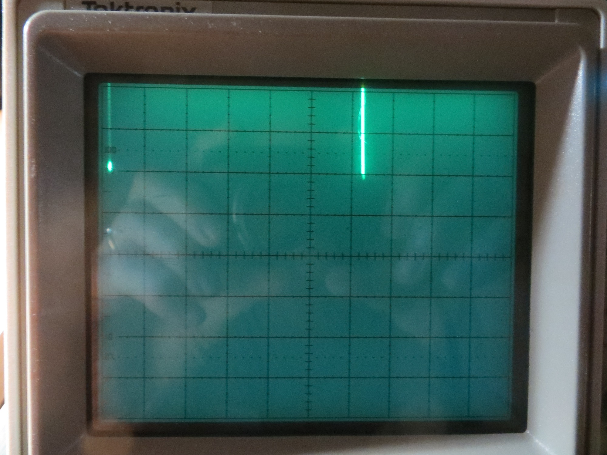
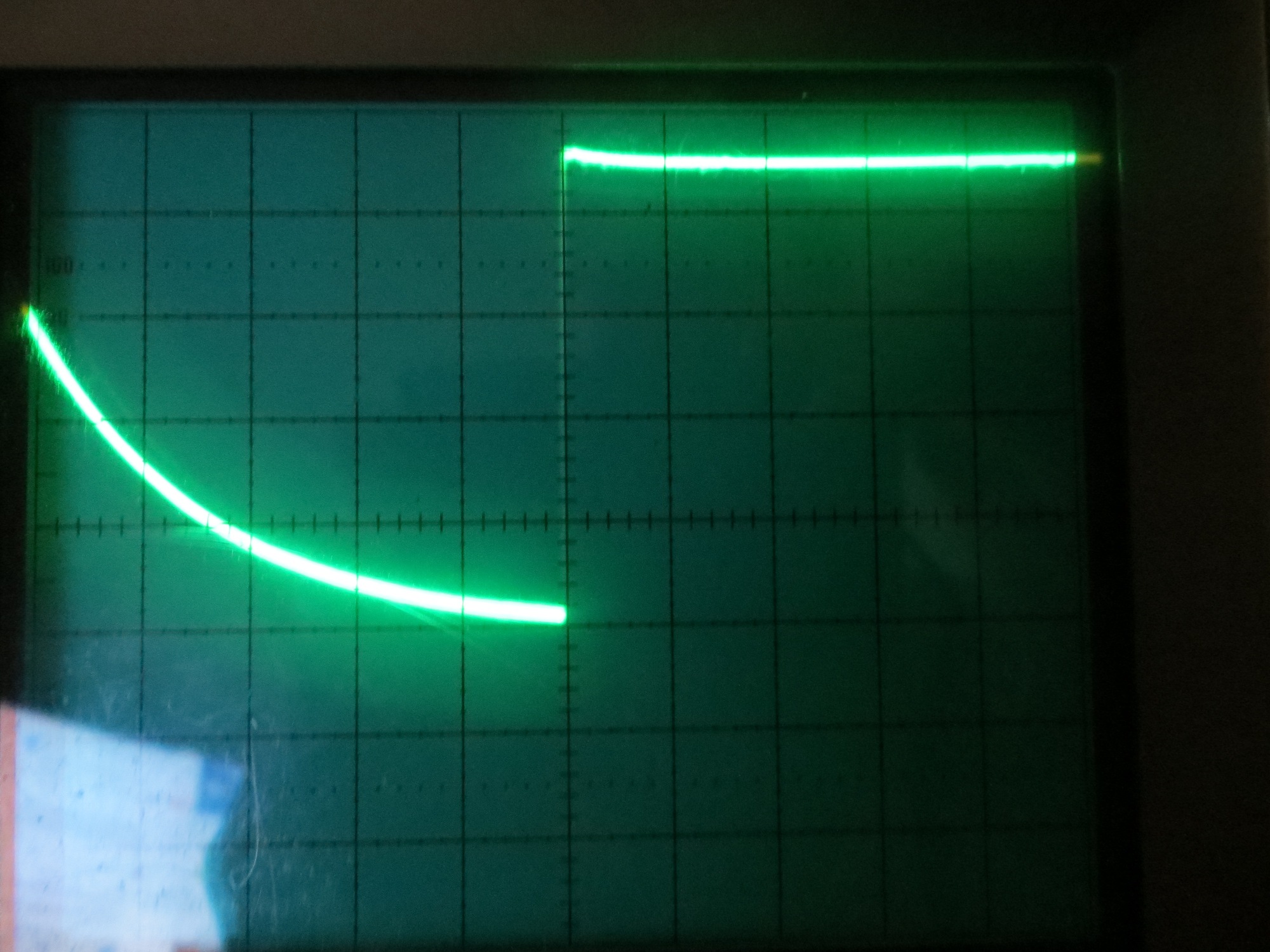
0.1 msec/div closeup of the LOW period between the ‘bottom’ and ‘top’ of the Loop() section. Note the curved section at the bottom is due to the LED turning OFF.
The first image above at 20msec/div shows what I expected to find – that the LIDAR-Lite V1 unit is capable of taking measurements with an approximate 20msec cycle time. This should work fine for my Wall-E spinning LIDAR robot, as interrupts from the tach wheel sensor occur at about 25msec intervals.
However, after a few minutes, the scope display (again at 20msec/div) showed that the system stopped responding a the 20msec rate, and instead started responding no faster than about 100-110msec, WAY too slow for my spinning LIDAR application. I have no idea why this happens, but I am hoping the Pulsed Light guys will tell me that I have simply screwed something up and doing XYZ will fix it.
The last image above at 0.1msec/div shows a closeup of the OFF period. The curved bottom section is due to the fact that the LED turns OFF at about 3 Vdc, and below that the remaining energy has to be drained off through a high impedance.
After sending this information off to the PL guys, I started thinking that maybe the apparent change from ’20msec’ mode to ‘100msec’ mode might possibly be due to the extremely short LOW duration (about 100 usec or less) and the fact that the LOW doesn’t go much below about 3Vdc. Although I didn’t really believe it, I thought it was just barely possible that my trusty O’Scope was just missing these very short transitions after a time, and the whole problem was an O’Scope problem and not a LIDAR problem. So, in order to put this possibility to rest, I modified the code again to extend the LOW duration by 1msec with a delay(1) statement just after the line that sets the LED output LOW (essentially adding an extra 1msec delay between the LOW and HIGH lines). After uploading this to the Uno, I captured the following O’Scope waveforms.

After addition of a 1msec delay to the LOW period. Showing the ’20msec’ mode at 10msec/div
After addition of a 1msec delay to the LOW period. 2msec/div
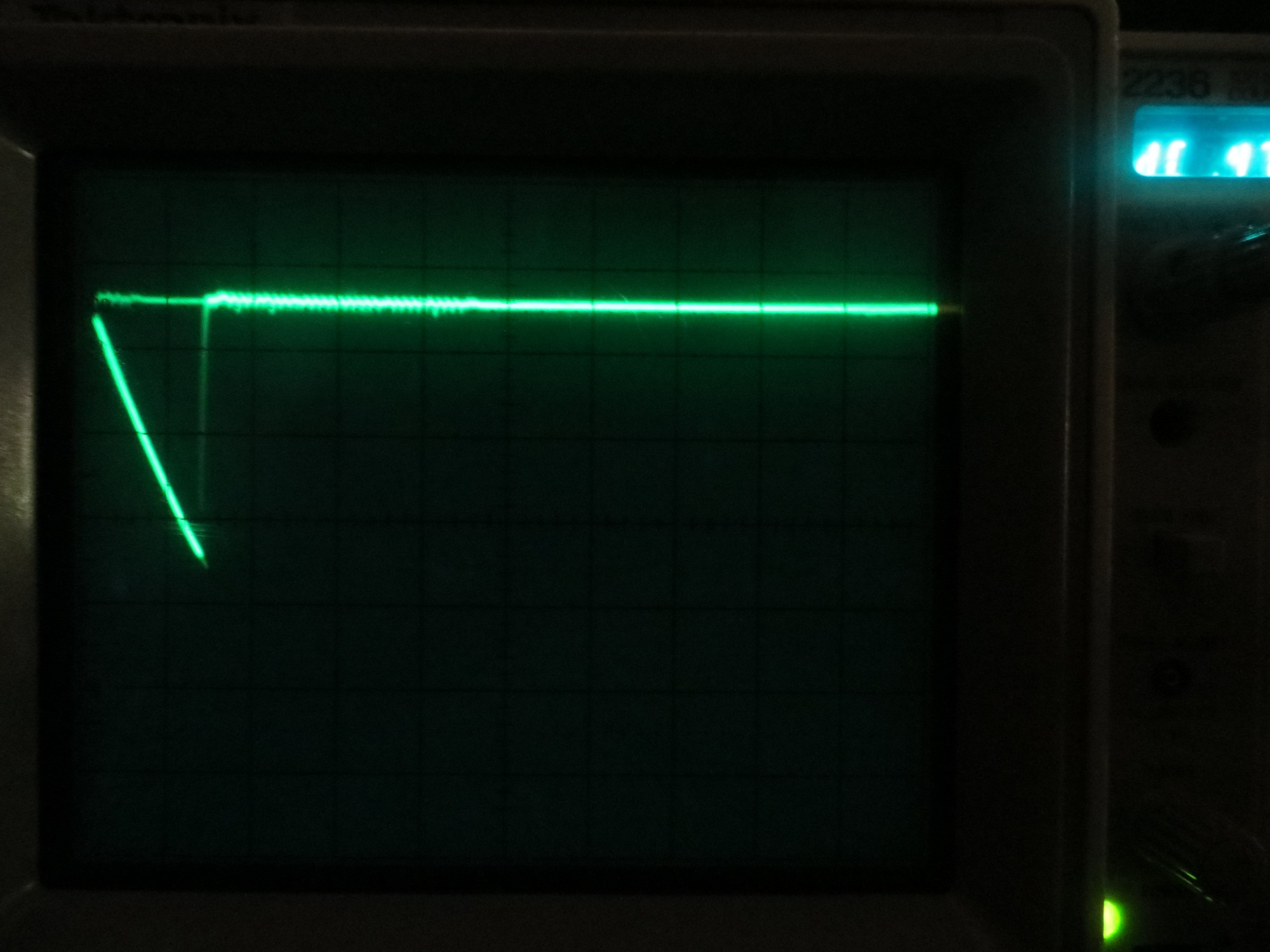
After addition of a 1msec delay to the LOW period. 0.2 msec/div closeup of the LOW period between the ‘bottom’ and ‘top’ of the Loop() section. Note the curved section at the bottom is due to the LED turning OFF.
After addition of a 1msec delay to the LOW period. This shot was taken about 45 minutes after startup, showing that the system has made an uncommanded transitioned to ‘100msec’ mode
As shown in the above photos, I got essentially the same behavior as before. The system came up in ’20msec’ mode, but made an uncommanded transition to ‘100msec’ mode about 45 minutes after startup.
So, something is happening here, but I don’t know what it is. It ‘smells’ like a heat-related problem, but that doesn’t make a whole lot of sense, as I’m running this in an air-conditioned environment, and there isn’t that much power being used as it is. As I mentioned above, I’m hoping it’s just something dumb that I’m doing that is causing this, but I have no clue what that might be.
There is one other possibility that just popped into my head. I’m using Uno clones rather than actual Arduino boards. I guess it is just barely possible that the problem is in the Uno board, not the LIDAR. Maybe the I2C lines get flaky after some time, and start sending bad requests to the LIDAR or not properly processing LIDAR responses? I’m thinking I might want need to acquire some genuine (Genuino?) Arduino Uno boards to eliminate this possibility.
Stay tuned!
Frank
Pingback: More Pulsed Light 'Blue Label' LIDAR testing - Paynter's Palace
I have the same problem, but the device switches faster. It sends really fast for a couple of seconds and then starts sending about 10 measurements/sec or less. I am even using a different library, seems it is a hardware problem with the sensor itself.
Marcin,
Thanks for the post – it’s always nice to know that others have seen the same phenomenon, and that you aren’t really crazy ;-).
FWIW, the V2 ‘Blue Label’ version doesn’t exhibit this problem, at least not as far as I can tell. I never did get any sort of reply back from Pulsed Light, though ;-(.
Frank