Posted 04/04/2015
In my ‘Baby Gets a New Bumper’ I described my efforts to build a bumper for the robot that would defeat my robot’s tendency to hug chair legs. In that post I described two bumper versions, the second of which did a credible, but not perfect, job of eliminating ‘chair leg love’.
In a subsequent Skype session with my grandson, he suggested that the front end of the bumper could be extended and curved slightly to eliminate the current small (but not zero) flat spot that still allows Wall-E to occasionally be successful in wrapping himself around a chair leg. So, with me watching from Ohio via screen sharing, Danny in Missouri pulled up the shared bumper design in TinkerCad and went through a number of quick iterations, resulting in a much improved design. I then downloaded this design to my PC back here in Ohio, printed it out on my PowerSpec PRO 3D printer, and installed it on Wall-E. Total time from Skype session to printed part on the robot – about 12 hours (it would have been faster, but I went off and played bridge for 3-4 hours).
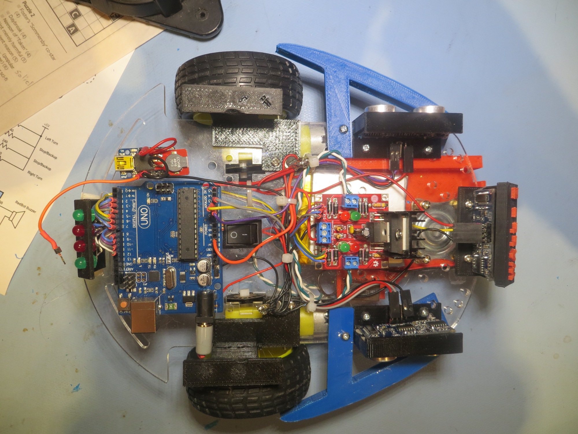
Top view of Baby’s new bumpers, Version 2
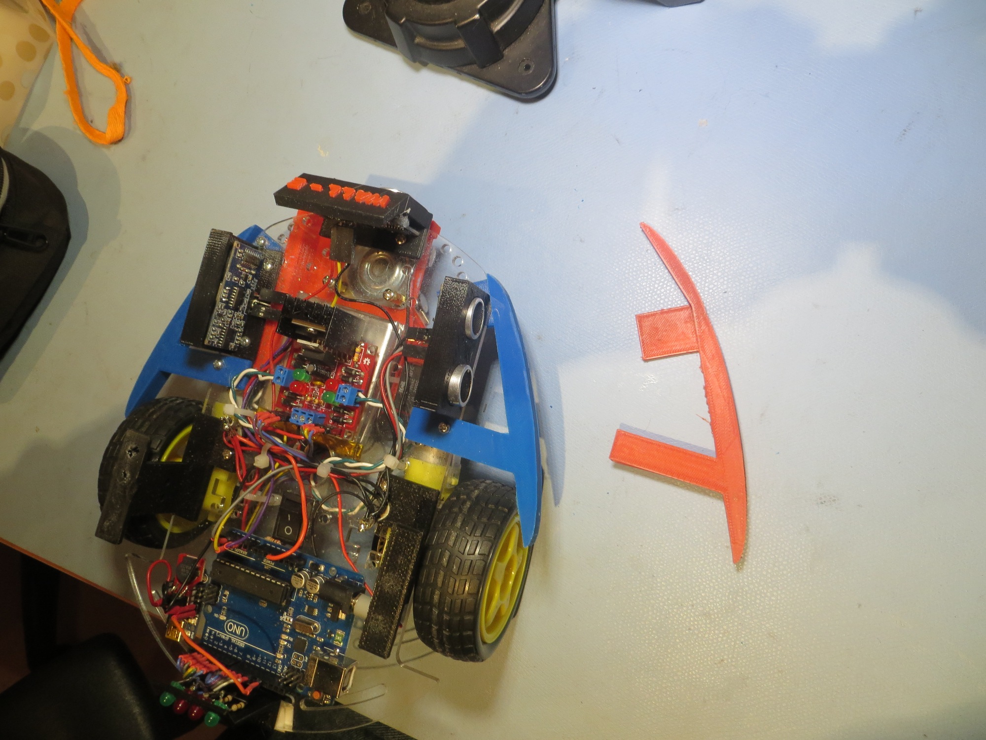
Getting ready to replace the right V2 bumper with V3
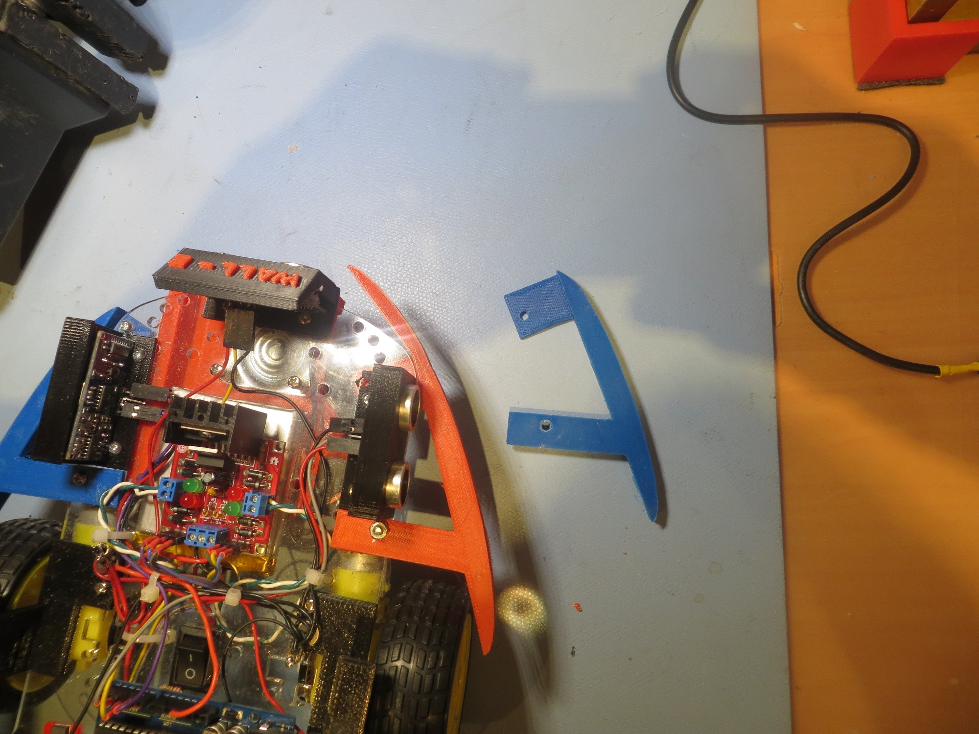
After replacing the V2 bumper with Version 3
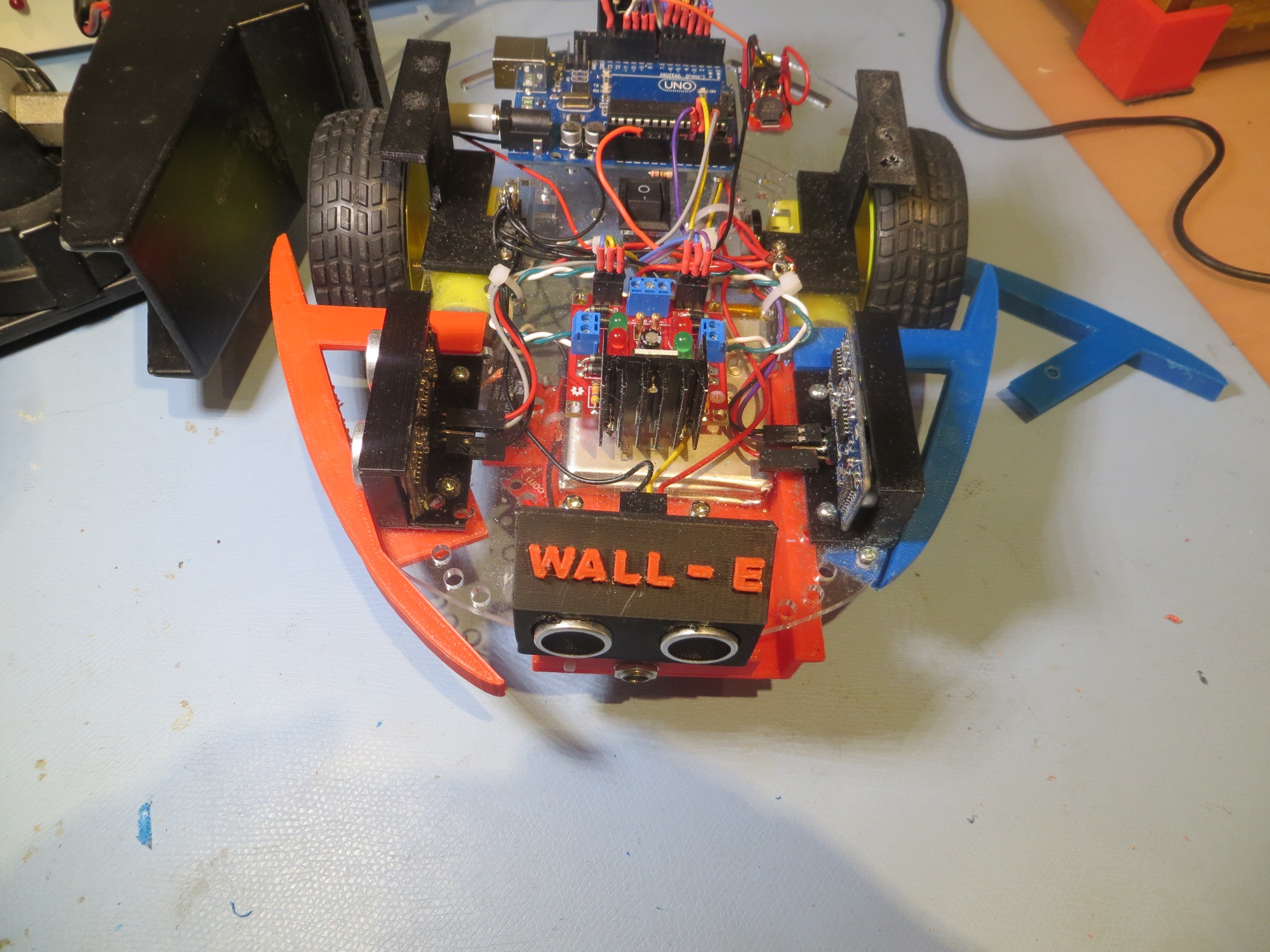
Right side is V3, Left is V2
After getting the V3 bumper installed on Wall-E’s right side, it was immediately clear that the V3 bumper was better, but could also stand to be improved slightly (having a 3D printer and design tools like TinkerCad, not to mention a willing grandson, makes incremental improvement cheap and easy). If the added section were rotated just slightly inboard, it would very nearly mate with the existing front ping sensor bracket and form a seamless slide surface when Wall-E next encounters a chair leg. Just eyeballing, the required angle looked to be about 10-15 degrees – but I don’t need to eyeball- I have the technology! ;-). Anyway, I sucked the below image into Visio and used it’s dimensioning tools to measure the angle. Turned out my eyeball was pretty close – about 10 degrees should do the trick (along with a length reduction of 5-10mm).
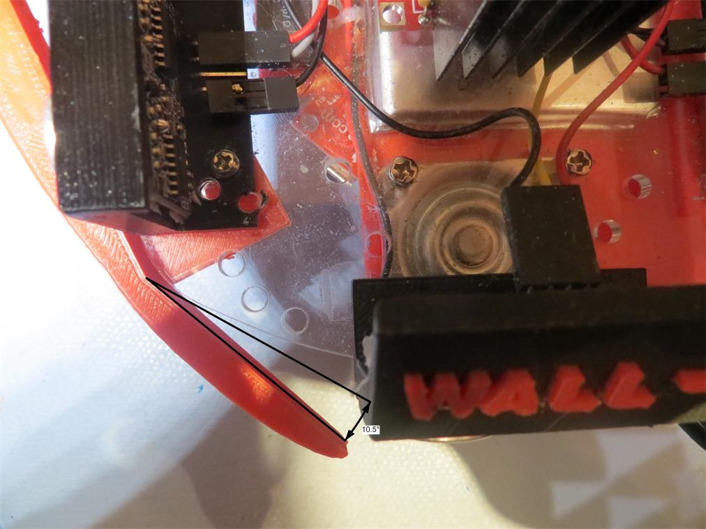
V3 Bumper Additional Angle Dimension
Frank