In a previous lifetime I was a cross-country glider pilot. This means I would regularly fly an aircraft with no engine up to six or seven hours and cover hundreds of miles without landing. Expert glider pilots can do this at average speeds approaching or exceeding interstate speed limits. Since gliders must stop occasionally to regain lost altitude in rising air currents (called thermals), their inter-thermal speed has to be significantly higher than the average, meaning a glider flying along an interstate will easily outpace the cars and trucks below.
Anyway, a friend from that previous life showed me a clay model of a custom joystick handle he was working on. The model was intended to incorporate a complex instrument remote control panel in the top of the joystick, where the push-to-talk (PTT) switch would normally go. When he first showed it to me, I was just thinking about getting into 3D printing and in my ignorance I thought this would be a perfect 3D printing project (little did I know at the time!). Later on when I had just ordered (but not yet received) my PrintrBot Simple Metal Kit I asked him to send me his clay model, and promised him I would at least make the effort to turn his clay model into a finished 3D printed product. This is the story of how I went from 3D ignoramus to Joystick hero in a few short weeks.
07/28/14 Capture using Autodesk’s Catch/123d: I’ve gone through this now a couple of times with BZ’s joystick, and I am now starting to get some clues.
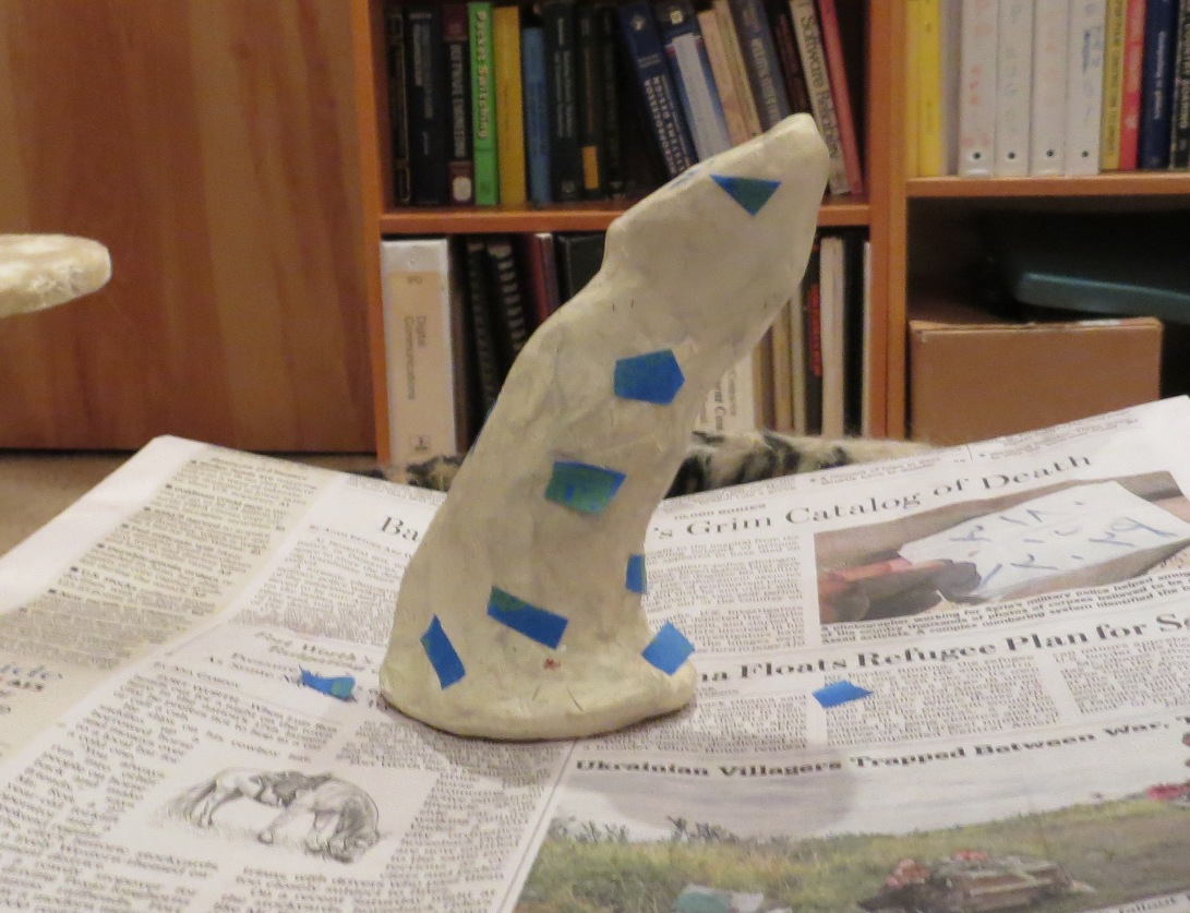
- The first time through was with just some painter’s tape patches placed on the joystick surface to give some reference points. This worked, but not very well. The patches didn’t stick very well due to the oil in the clay, and I got a number of unstitched photos. Also, I couldn’t manually stitch photos together. just never worked

Joystick with blue painter’s tape ‘stickies’
- Next time through I used narrow strips of painter’s tape, wound around the joystick in several places. This worked MUCH better, and in fact I had zero unstitched photos, and was eventually able to generate a full 3D STL file editable in 123d Design and TinkerCad (see below). However, the only fly in the ointment was that the painter’s tape wasn’t completely conformal with the joystick surface in several places, and this came through on the model as raised ridges.
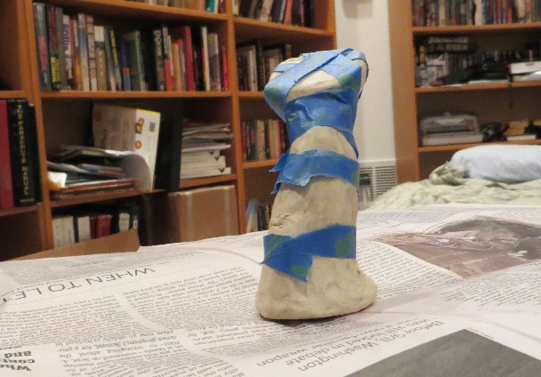
Joystick wound with strips of blue painter’s tape
- The third try was to replace the painter’s tape with felt-tipped marker markings. The thought was that this would be more conformal to the surface, and if done properly would also be appropriate for automatic stitching. However, what actually happened was that the model came through OK, but with many unstitched photos. Then when I laboriously manually stitched a number of photos into the model, the re-submission crashed. ouch! This problem continued even if I re-submitted after stitching only one photo. This was all done with the PC version, so I tried again with the online version.
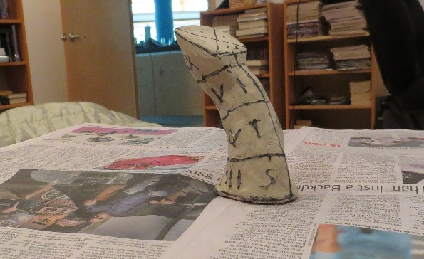
Joystick with Sharpie pen markings for surface contrast
- In the online version, I see that I have a number of projects that appear to be In processing’, even though they are older (as in days older) versions of the joystick process, and there doesn’t appear to be any way to remove them!. The Sharpie’ version is shown to be complete, and when I open it in the online version it looks great, but in the online version there is no lasso’ tool for removing all the background elements.

08/07/14: Working with a newer version of 123 Catch
- A newer version of 123 Catch became available in the last few days, so I decided to try a new capture using my photos from the Sharpie’ version of BZ’s joystick. This time when I uploaded the photos, I didn’t get any unstitched images. yay!!
- I discovered the mesh resolution’ setting in Catch, and was able to change the mesh resolution from Mobile’ to Maximum’. This also takes a selection area as a parameter, and re-meshes only the portion of the capture within the selection, so it takes much less time than doing the entire scene. Remeshing took only a few minutes with the selection limited to just the area around the joystick.
08/09/14 – Still working on the Sharpie’ joystick: I was able to print a ½ scale model of the joystick, but I discovered it was all solid inside, notwithstanding the hollow’ attribute advertised by the Catch/3D Print operations above. Also, I wasn’t able to figure out how to undo the minimum support’ setting that left the joystick on its side. So, I’m making another try at this from scratch and will try to document the steps more rigorously.
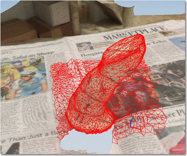
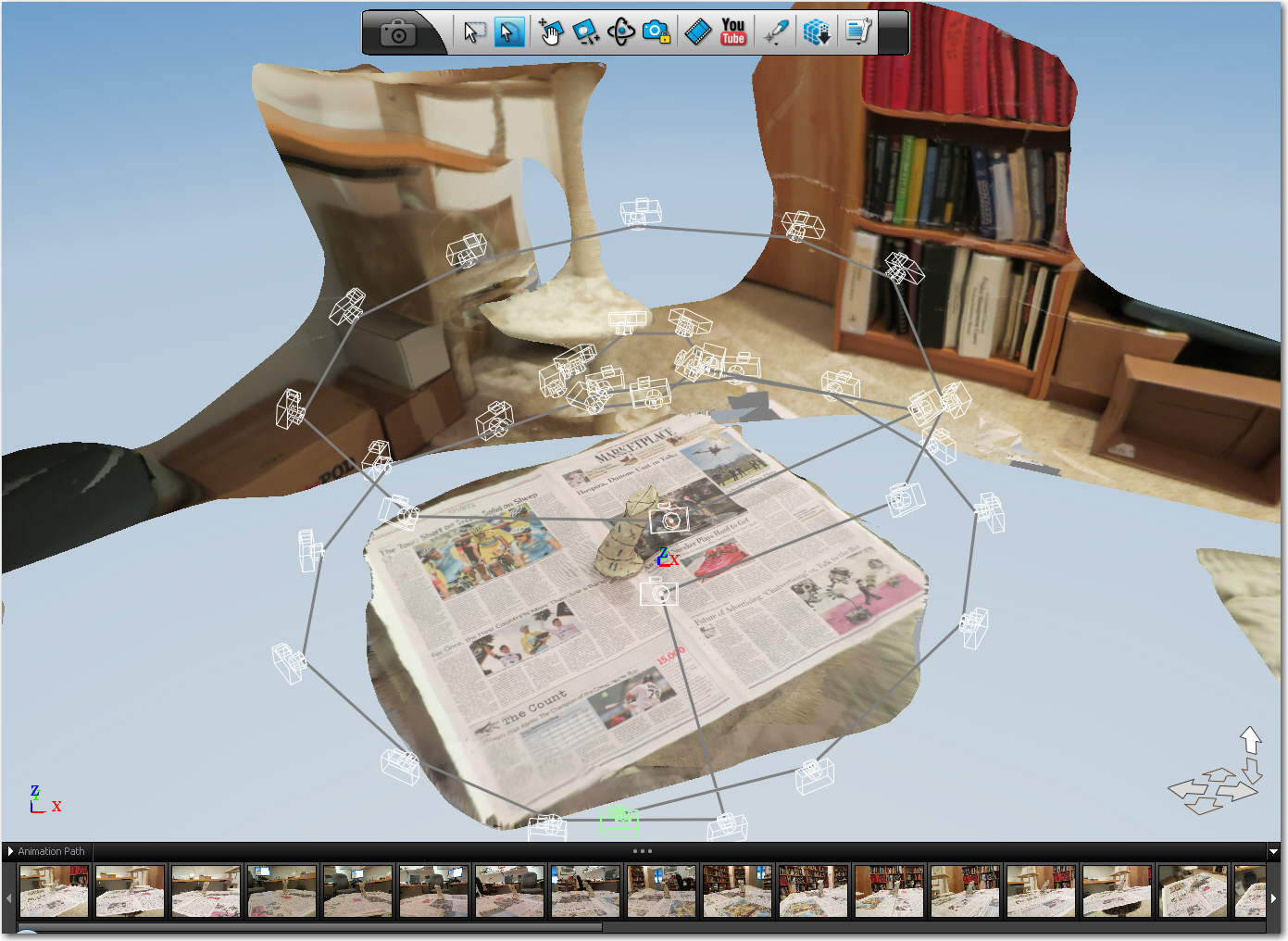
- Started a New Capture’ in 123 Catch, using the 07/28/14 Sharpie photos. This took a long time to process. Catch asked for a Capture file name, and suggested Capture_2014_08_09_06_17_31′ (date and time). When it completed, I was presented with the constructed model as shown below.

First successful capture of the ‘Sharpie’ model
- I did an immediate Save As at this point, and noticed I already had a Capture_2014_08_09_06_17_31′ folder and .3dp file saved in the same folder as the original Sharpie photos (140728_Sharpie Photos). I have seen this before, but AFAICT, this folder and file aren’t usable later. can’t figure that out. I cancelled the Save As operation.
- I found a 2011 tutorial at http://aucache.autodesk.com/au2011/sessions/4056/class_handouts/v1_AC4056%20-%20It%E2%80%99s%20a%20Snap!%20Take%20a%20photograph%20and%20create%20a%203D%20Model.pdf. This was apparently a presentation at an AutoDesk conference. This tutorial explained things like the photo lock’ mode (constrains the scene view to just the available discrete camera locations), but wasn’t all that helpful for my purposes.
- I somehow got into Photo Lock’ (PL) mode and now I can’t get out again! If I disable PL, I get a blank screen with just the camera locations and the coordinate axes shown. Hmm, I clicked on show mesh’ and now I have the scene back. weird. Yep. confirmed that you have to have show mesh’ checked to get *anything*!
- OK, selected the lasso selection tool and deleted everything around the joystick. Shit! I deleted a small section of the mesh, and *then* got a dialog warning me that I needed to make sure I was in the correct mesh quality setting, or edits might be lost. So I tried to undo the mesh edit, only to find there’s no UNDO function!
- Used the rectangle selection tool to select just a small area around the joystick for re-meshing (including part of the deleted area from the previous bullet) as shown. Note that I rotated the view to a fairly high angle so that my selection was restricted to just the newspaper around the joystick. omitting any of the office background.
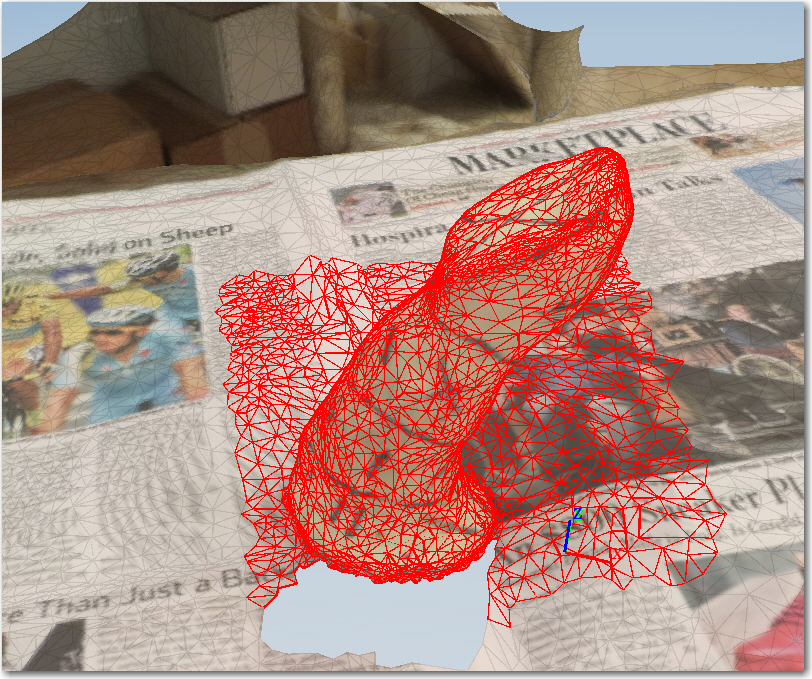
Remeshing a selection of the original Sharpie model
- Selected the Remesh icon and selected Maximum Quality’. This produced a dialog with the original capture name (Capture_2014_08_09_06_17_31) which I assume is a reference to the previously uploaded photos. Curiously, this field is editable, giving the impression I could have used another name. maybe then it would have saved the re-mesh into a different capture structure?
- OK, the remesh finished successfully, leaving me with a rectangular patch from the original scene.
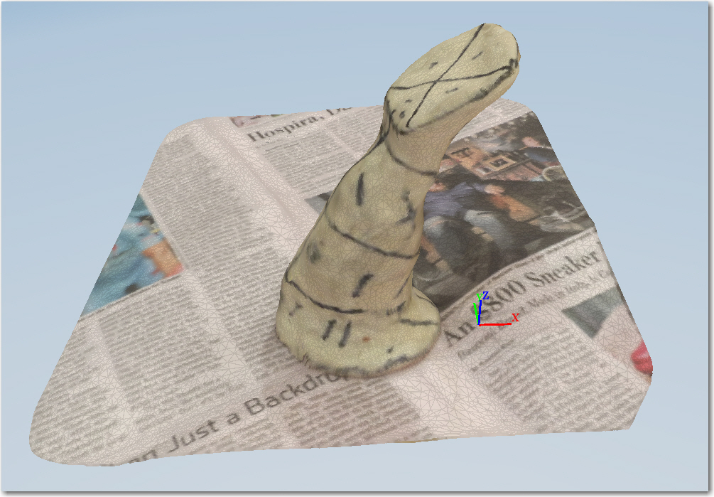
Sharpie model after remeshing a selected portion of the original scene
- I saved this result as 140809 Sharpie Capture After Remesh.3dp’. I don’t really know if this will actually save anything or be useful later, but I thought it couldn’t hurt. I also saved it as an .OBJ file, which might actually be more useful/permanent. By default, both these files were saved in the same folder as the original capture photos, i.e. F:\3D Projects\Joystick\140728_Joystick Sharpie Photos’. The .3dp file is only 5.3KB, indicating that (as noted in the 2011 presentation) it only contains references to the online location of the Capture files, not the files themselves). The .OBJ file is a more respectable 4 MB.
- Back in Catch, I used the lasso tool to further refine the mesh to just the joystick, and saved this in both .3dp and .OBJ format. Even after being very careful with the lasso operation, I wound up with a big hole on the right side of the joystick base. I saw this before on a previous run through, but found that the 123d Print application was able to repair’ the hole. strange.
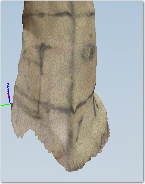
After the ‘lasso and delete’ operation, I have a big hole in the bottom of the joystick!
- Saved this as 140809 Sharpie Capture After Remesh And Lasso’ .3dp and .obj.
- Clicked on the 3D Print button to launch the AutoDesk MeshMixer app. By default, this opens with the joystick in the minimum support’ orientation. no idea how to change it back to the upright orientation (note – as it turns out, this isn’t the ‘minimum support’ orientation – it just looks like it).
- Clicked on the Modify’ icon and got a warning message about losing unsaved changes. Clicked OK, and got the following:
- After fooling around in the MeshMixer for an hour or so, I finally gave up on this model. I couldn’t figure out a way to add surface material to repair the hole. Still fooling around, I selected Edits’ and Overhangs’ and MeshMixer crashed. oops!
- Back in Catch, I opened the file 140809 Sharpie Capture After Remesh.3dp’, and it indeed opened the correct project, as shown.
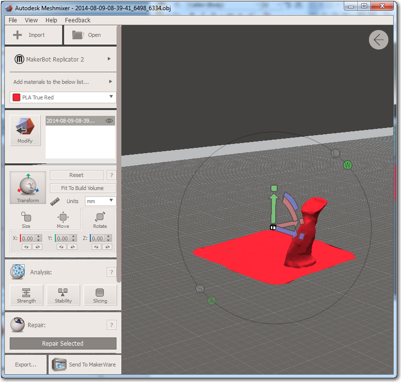
- This time I used this model to go to 3D Print, (which launches Autodesk’s MeshMixer app) and got the following default layout.
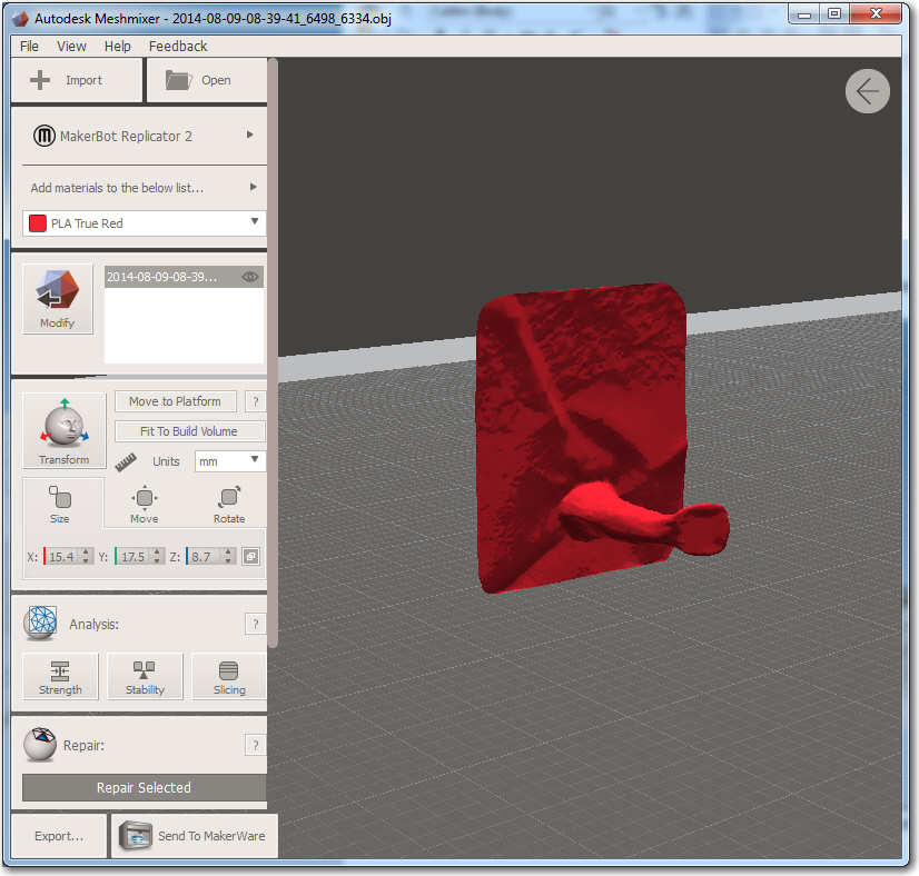
- This is actually a bit nicer to work with, as the section of newsprint gives me a decent X-Y plane to work with for transforming the joystick to the upright position. After rotating 270 deg around X axis, and then Move to Platform’ to move the base down to the Z = 0 level, I got the following.
After a 270 degree rotation around the X axis and then ‘Move to Platform’
- Hmm, I tried to go back to the Modify’ mode in MM and discovered you can’t do that. Apparently there are two distinct MM modes. Modify’ and Print’ and they aren’t integrated. Transforms/Translations in Print’ mode don’t flow back into Modify’ mode. bummer! To get to Print’ mode, click on Send to Print’. To get back to Modify’ mode, click on Modify’.
- OK, finally figured out Rot/Translate in Modify’ view. The center box’ is for linear scaling for all axes. The colored arcs are for rotating about the various axes, and the triangles are for translating. After figuring this out, I was able to rotate the joystick to an upright orientation, as shown. I still have no idea what the L’, S’, A’, and W’ labels are for.
- Exported the model as 140809_MeshMixer_Rev3.stl’ in Ascii STL format and tried to import it into TinkerCad, but it doesn’t seem to want to import at all. Imports easily into 123D Design, however. Tried this trick again with the binary formatted STL file. The binary version does import into TinkerCad (and 123d Design) OK. yay!!
- OK, figured out how to use the Select tools to delete the newsprint mesh, leaving only the joystick (hopefully), as shown.
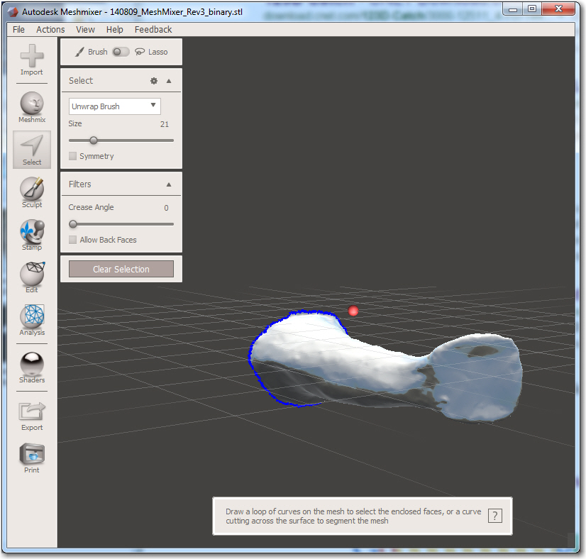
Joystick after newsprint removal
- After this I was able to use the transform tools in Modify’ mode to rotate/translate the joystick into a more understandable orientation, and saved the model as 140809_MM_Rev5_RotXlt_bin.stl’.
- Next I tried using the Edit/Plane Cut tool to cut off the garbage at the bottom of the joystick, as shown below. I accepted the transform, which gave me just a disk. oops!
- Tried again, with the cut plane rotated 180 degrees. This time things worked out much better. The selection and the result are shown below.
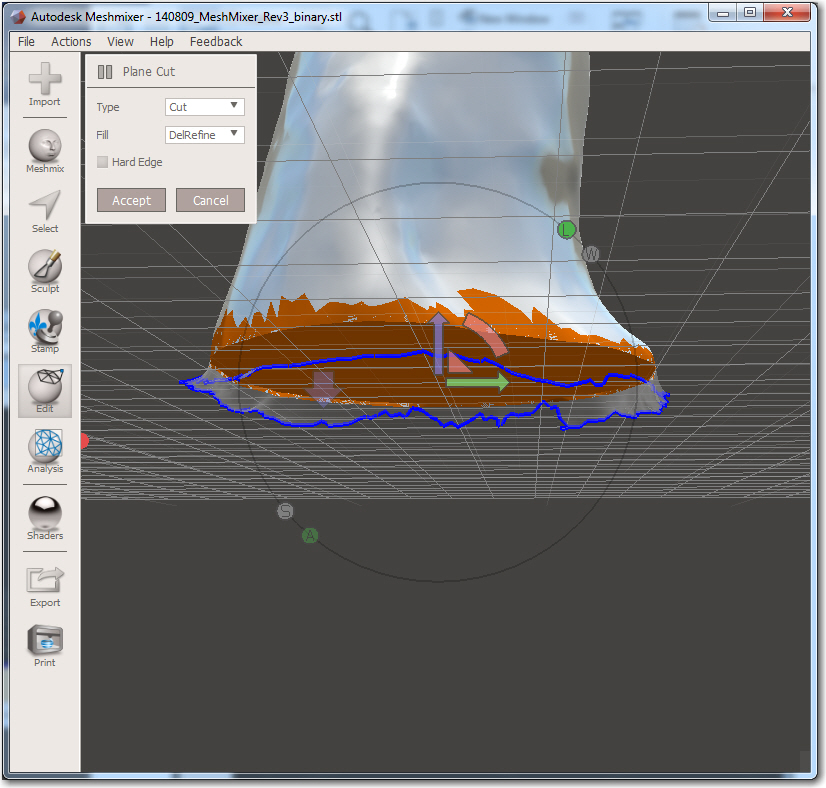
Plan cut operation with the plane rotated 180 degrees from the original
-
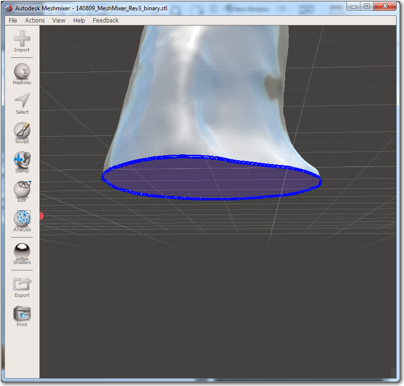
After proper plane cut selection, the joystick bottom is nice and flat


Saved this as 140809_MM_Rev6_PlaneCut_bin.stl. Then I opened it in TinkerCad successfully, as shown below. Note that the joystick in TinkerCad is still laying on its side, so maybe the transformations in MM aren’t getting into the export file?
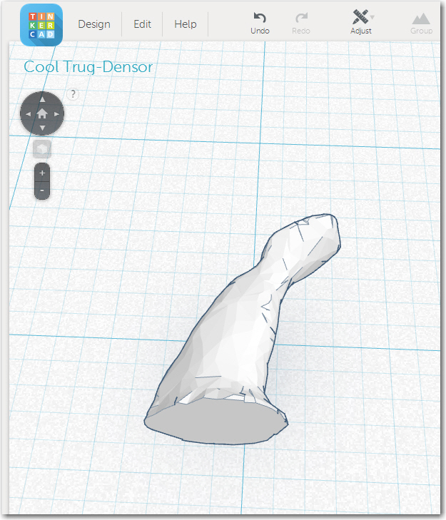
TinkerCad model after successful Plane Cut operation. Note that the model is on its side
- Tried undoing the rotation transformation in MM and re-exporting. OK, this worked! Apparently, the coordinate systems in MM and the rest of the world are defined differently. so if going from Catch to MM to TinkerCad, don’t have to rotate in Meshmixer.
After undoing the rotations & translations
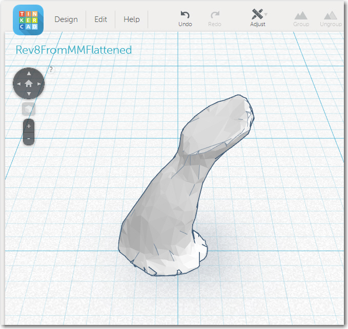
- After this, I went back into MM and used the Flatten’ brush to smooth out some of the rough spots, saved it as Rev8Flattened, and imported that back into TC

Summarizing lessons learned so far:
- MeshMixer can be used to remove the newsprint background from the Catch export
- No need to rotate/translate in MM when going from Catch to MM to TinkerCad
- Probably need to establish a scale in Catch, as the resulting model winds up being very small in MM and TC (3.5 x 6 mm). OTOH, I can just as easily establish the scale in TC (this is what I wound up doing).
08/09/14: Starting from 140809 Sharpie Capture After Remesh.3dp:
- Click on 3DPrint to launch MeshMixer and load the file: Opens as 2014-08-09-13-06-47_8466_41.obj’ in MM, with the Print’ mode active.
- Click on Modify’ to get into that mode.
- In Modify’ mode:
o Analysis/Inspector/Auto Repair All
o Edit/Plane Cut & adjust as low as possible with a solid bottom. This should also remove much of the newsprint area.
o Choose Select tool with Unwrap Brush active and double-click anywhere in the remaining newsprint area to select it all. Then hit DELETE to delete it all. Save this state as a .MIX file, and export it as a binary STL. Check in TC to make sure it can be imported properly (140809_MeshMixer_Rev4_JoystickOnly_binary.stl)
o Choose Sculpt’ and the Flatten’ brush. Run the brush over the entire surface, flattening out minor bumps and wiggles. Spent some quality time on the top surface, flattening it out for future work. Went through a bunch of revisions, but saved the last one as 140809_MM_Rev9_Flattened_bin.stl.
08/09/14 – in TinkerCad:
- Imported 140809_MM_Rev9_Flattened_bin.stl. This was very small, but it was properly oriented with the joystick upright. yay!
- Found the all axis scale’ function. Alt-Shift-Corner resizer. This allowed me to scale all axes until the vertical dimension matched the measured 121.5mm from the original clay model. Saved this in TinkerCad to 140809 Rev 9 Scaled to Clay Model’
Next up – Modifying the basic model in TinkerCad to incorporate the mounting hole for the joystick, wiring passage to the joystick head, and mounting arrangements for an auxiliary switch and the ClearNav remote head. Stay tuned!