Posted 23 March 2022,
Earlier this month I was able to demonstrate a multi-lap left-side wall tracking run by Wall-E3 in my office ‘sandbox’. This post describes my efforts to extend this capability to right-side wall tracking.
Since I already had the left-side wall tracking algorithm “in the can”, I thought it would be a piece of cake to extend this capability to right-side tracking. Little did I know that this would turn into yet another adventure in Wonderland – but at least when I finally made it back out of the rabbit-hole, the result was a distinct improvement over the left-side algorithm I started with. Here’s the left-side code:
|
1 2 3 4 5 6 7 8 9 10 11 12 13 14 15 16 17 18 19 20 21 22 23 24 25 26 27 28 29 30 31 32 33 34 35 36 37 38 39 40 41 42 43 44 45 46 47 48 49 50 51 52 53 54 55 56 57 58 59 60 61 62 63 64 65 66 67 68 69 70 71 72 73 74 75 76 77 78 79 80 81 82 83 84 85 86 87 88 89 90 91 92 93 94 95 96 97 98 99 100 101 102 103 104 105 106 107 108 109 110 111 112 113 114 115 116 117 118 119 120 121 122 123 124 125 126 127 128 129 130 131 132 133 134 135 136 137 138 139 140 141 142 143 144 145 146 147 148 149 150 151 152 153 154 155 156 157 158 159 160 161 162 163 164 165 166 167 168 169 170 171 172 173 174 175 176 177 178 179 180 181 182 183 184 185 186 187 188 189 190 191 192 193 194 195 196 197 198 199 200 201 202 203 204 205 |
void TrackLeftWallOffset(float kp, float ki, float kd, float offsetCm) { //Purpose: Track left wall at specified offset // Inputs: // kp,ki,kd = float objects denoting PID parameters for PIDCalcs() // offsetCm = float denoting desired wall offset, in Cm // Plan: // Step1: If robot is already close to desired offset, just turn parallel and go // Step1: Otherwise, get current robot orientation and offset wrt wall // Step2: Move to offset distance and parallel to wall // Step3: Track wall at desired offset //Notes: // 06/21/21 modified to do a turn, then straight, then track 0 steer val mSecSinceLastWallTrackUpdate = 0; float lastError = 0; float lastInput = 0; float lastIval = 0; float lastDerror = 0; float spinRateDPS = 30; AnomalyCode errcode = NO_ANOMALIES;//03/06/22 mvd here to make global to function GetRequestedVL53l0xValues(VL53L0X_LEFT); //update glLeftSteeringVal myTeePrint.printf("\nIn TrackLeftWallOffset with Kp/Ki/Kd = %2.2f\t%2.2f\t%2.2f\n", kp, ki, kd); myTeePrint.printf("\nIn TrackLeftWallOffset with LR/LC/LF = %d\t%d\t%d\n", glLeftRearCm, glLeftCenterCm, glLeftFrontCm); //Step1: If robot is already close to desired offset, just turn parallel and go if (abs(WALL_OFFSET_TGTDIST_CM - glLeftCenterCm) <= (uint16_t)((float)WALL_OFFSET_TGTDIST_CM/10.f)) { myTeePrint.printf("At %d with desired offset = %d: close enough - just parallel and go\n", glLeftCenterCm, WALL_OFFSET_TGTDIST_CM); RotateToParallelOrientation(TRACKING_LEFT); } else //OK, have to move to offset distance before rotating back to parallel { //Step1: Get current robot orientation and offset wrt wall float cutAngleDeg = WALL_OFFSET_TGTDIST_CM - (int)(glLeftCenterCm);//positive inside, negative outside desired offset //myTeePrint.printf("R/C/F dists = %d\t%d\t%d Steerval = %2.3f, CutAngle = %2.2f\n", // glLeftRearCm, glLeftCenterCm, glLeftFrontCm, glLeftSteeringVal, cutAngleDeg); //07/05/21 implement min cut angle if (cutAngleDeg < 0 && abs(cutAngleDeg) < WALL_OFFSET_APPR_ANGLE_MINDEG) { //myTeePrint.printf("(cutAngleDeg < 0 && abs(cutAngleDeg) < %d -- setting to -%d\n", WALL_OFFSET_APPR_ANGLE_MINDEG, WALL_OFFSET_APPR_ANGLE_MINDEG); cutAngleDeg = -WALL_OFFSET_APPR_ANGLE_MINDEG; } else if (cutAngleDeg > 0 && cutAngleDeg < WALL_OFFSET_APPR_ANGLE_MINDEG) { //myTeePrint.printf("(cutAngleDeg > 0 && abs(cutAngleDeg) < %d -- setting to +%d\n", WALL_OFFSET_APPR_ANGLE_MINDEG, WALL_OFFSET_APPR_ANGLE_MINDEG); cutAngleDeg = WALL_OFFSET_APPR_ANGLE_MINDEG; } //Step2: get the steering angle from the steering value, for comparison to the computed cut angle //positive value means robot is oriented away from wall float WallOrientDeg = GetWallOrientDeg(glLeftSteeringVal); //myTeePrint.printf("R/C/F dists = %d\t%d\t%d Steerval = %2.3f, SteerAngle = %2.2f, CutAngle = %2.2f\n", // glLeftRearCm, glLeftCenterCm, glLeftFrontCm, glLeftSteeringVal, WallOrientDeg, cutAngleDeg); //Step3: now decide which way to turn. int16_t fudgeFactorCm = 0; //07/05/21 added so can change for inside vs outside starting condx if (cutAngleDeg > 0) //robot inside desired offset distance { if (WallOrientDeg > cutAngleDeg) // --> WallOrientDeg also > 0, have to turn CCW { //myTeePrint.printf("CutAngDeg > 0, WallOrientDeg > cutAngleDeg - Turn CCW to cut angle\n"); SpinTurn(true, WallOrientDeg - cutAngleDeg, spinRateDPS); // } else //(WallOrientDeg <= cutAngleDeg)// --> WallOrientDeg could be < 0 { //myTeePrint.printf("CutAngDeg > 0, WallOrientDeg < cutAngleDeg\n"); SpinTurn(false, cutAngleDeg - WallOrientDeg, spinRateDPS); //turn diff between WallOrientDeg & cutAngleDeg } fudgeFactorCm = -10; //07/05/21 don't need fudge factor for inside start condx } else // cutAngleDeg < 0 --> robot outside desired offset distance { if (WallOrientDeg > cutAngleDeg) // --> WallOrientDeg may also be > 0 { //robot turned too far toward wall myTeePrint.printf("CutAngDeg < 0, WallOrientDeg > cutAngleDeg\n"); SpinTurn(true, WallOrientDeg - cutAngleDeg, spinRateDPS); // } else// (WallOrientDeg < cutAngleDeg)// --> WallOrientDeg must also be < 0 { //robot turned to far away from wall myTeePrint.printf("CutAngDeg < 0, WallOrientDeg <= 0\n"); SpinTurn(false, cutAngleDeg - WallOrientDeg, spinRateDPS); //null out WallOrientDeg & then turn addnl cutAngleDeg } fudgeFactorCm = 10; //07/05/21 need fudge factor for outside start condx } //myTeePrint.printf("fudgeFactorCm = %d\n", fudgeFactorCm); //delay(1000); //Step4: Figure out how far to travel to get to desired offset //adjust so offset capture occurs at correct perpendicular offset float adjfactor = cos(PI * cutAngleDeg / 180.f); float numerator = (float)WALL_OFFSET_TGTDIST_CM; float adjOffsetCm = (numerator / adjfactor); adjOffsetCm += fudgeFactorCm; //fudge factor for distance measurements lagging behind robot's travel. //myTeePrint.printf("\nat approach start: cut angle = %2.3f, adjfactor = %2.3f, num = %2.2f, adjOffsetCm = %2.2f\n", //cutAngleDeg, adjfactor, numerator, adjOffsetCm); GetRequestedVL53l0xValues(VL53L0X_ALL); //added 09/05/21 int16_t err = glLeftFrontCm - (uint16_t)adjOffsetCm; //neg for inside going out, pos for outside going in int16_t prev_err = err; //myTeePrint.printf("At start - err = prev_err = %ld\n", err, prev_err); WallOrientDeg = GetWallOrientDeg(glLeftSteeringVal); myTeePrint.printf("R/C/F dists = %d\t%d\t%d Steerval = %2.3f, SteerAngle = %2.2f, CutAngle = %2.2f, err/prev_err = %li\n", glLeftRearCm, glLeftCenterCm, glLeftFrontCm, glLeftSteeringVal, WallOrientDeg, cutAngleDeg, err); //myTeePrint.printf("Msec\tLFront\tLCtr\tLRear\tFront\tRear\tErr\tP_err\n"); //Step5: Move to desired offset //02/25/22 added check for error conditions (stuck, obstacle, dead battery, etc) AnomalyCode errcode = NO_ANOMALIES; while (((cutAngleDeg > 0 && err < 0) || (cutAngleDeg <= 0 && err >= 0)) && prev_err * err > 0 && errcode == NO_ANOMALIES) //sign change makes this < 0 { prev_err = err; //MoveAhead(MOTOR_SPEED_FULL, MOTOR_SPEED_FULL); MoveAhead(MOTOR_SPEED_HALF, MOTOR_SPEED_HALF); delay(100); glFrontdistval = GetFrontDistCm(); GetRequestedVL53l0xValues(VL53L0X_ALL); err = glLeftFrontCm - adjOffsetCm; //06/29/21 now adj for slant dist vs perp dist //myTeePrint.printf("%lu\t%d\t%d\t%d\t%d\t%d\t%ld\t%ld\n", // millis(), // glLeftFrontCm, glLeftCenterCm, glLeftRearCm, glFrontdistval, glRearCm, err, prev_err); CheckForUserInput(); errcode = CheckForErrorCondx(); } //Step6: now turn back the same (unadjusted) amount //myTeePrint.printf("At end of offset capture - prev_res*res = %ld\n", prev_err * err); //myTeePrint.printf("correct back to parallel (left side)\n"); SpinTurn(!(cutAngleDeg < 0), abs(cutAngleDeg), spinRateDPS); //have to use abs() here, as cutAngleDeg can be neg } WallTrackSetPoint = 0; //moved here 6/22/21 myTeePrint.printf("\nTrackLeftWallOffset: Start tracking offset of %2.2fcm with Kp/Ki/Kd = %2.2f\t%2.2f\t%2.2f\n", offsetCm, kp, ki, kd); //myTeePrint.printf("Msec\tFdir\tCdir\tRdir\tRearD\tSteer\tSet\terror\tIval\tKp*err\tKi*Ival\tKd*Din\tOutput\tLspd\tRspd\n"); myTeePrint.printf("Msec\tLF\tLC\tLR\t\tRF\tRC\tRR\t\tF\tFvar\t\tR\tRvar\t\tSteer\tSet\tOutput\n"); //Step7: Track the wall using PID algorithm mSecSinceLastWallTrackUpdate = 0; //added 09/04/21 while (errcode == NO_ANOMALIES) { CheckForUserInput(); //this is a bit recursive, but should still work (I hope) //09/04/21 back to elapsedMillis timing if (mSecSinceLastWallTrackUpdate > WALL_TRACK_UPDATE_INTERVAL_MSEC) { digitalToggle(DURATION_MEASUREMENT_PIN2); //03/08/22 toggle duration measurement pulse mSecSinceLastWallTrackUpdate -= WALL_TRACK_UPDATE_INTERVAL_MSEC; //03/08/22 abstracted these calls to UpdateAllEnvironmentParameters() UpdateAllEnvironmentParameters();//03/08/22 added to consolidate sensor update calls errcode = CheckForErrorCondx(); //have to weight value by both angle and wall offset WallTrackSteerVal = glLeftSteeringVal + (glLeftCenterCm - WALL_OFFSET_TGTDIST_CM) / 1000.f; //update motor speeds, skipping bad values if (!isnan(WallTrackSteerVal)) { WallTrackOutput = PIDCalcs(WallTrackSteerVal, WallTrackSetPoint, lastError, lastInput, lastIval, lastDerror, kp, ki, kd); int glLeftspeednum = MOTOR_SPEED_QTR + WallTrackOutput; int glRightspeednum = MOTOR_SPEED_QTR - WallTrackOutput; glRightspeednum = (glRightspeednum <= MOTOR_SPEED_HALF) ? glRightspeednum : MOTOR_SPEED_HALF; glRightspeednum = (glRightspeednum > 0) ? glRightspeednum : 0; glLeftspeednum = (glLeftspeednum <= MOTOR_SPEED_HALF) ? glLeftspeednum : MOTOR_SPEED_HALF; glLeftspeednum = (glLeftspeednum > 0) ? glLeftspeednum : 0; MoveAhead(glLeftspeednum, glRightspeednum); //myTeePrint.printf("Msec\tLF\tLC\tLR\t\tRF\tRC\tRR\t\tF\tFvar\tR\tRvar\t\tSteer\tSet\tOutput\n"); myTeePrint.printf("%lu\t%d\t%d\t%d\t\t%d\t%d\t%d\t\t%d\t%d\t%2.2f\t%2.2f\t\t%2.2f\t%2.2f\t%2.2f\n", millis(), glLeftFrontCm, glLeftCenterCm, glLeftRearCm, glRightFrontCm, glRightCenterCm, glRightRearCm, glFrontdistval, glFrontvar, glRearCm, glRearvar, WallTrackSteerVal, WallTrackSetPoint, WallTrackOutput); } digitalToggle(DURATION_MEASUREMENT_PIN2); //03/08/22 toggle duration measurement pulse } } //Step8: Handle any anomalous conditions HandleAnomalousConditions(errcode, TRACKING_LEFT); } |
The above code works, in the sense that it allows Wall-E3 to successfully track the left-side wall of my ‘sandbox’. However, as I worked on porting the left-side tracking code to the right side, I kept thinking – this is awful code – surely there is a better way?
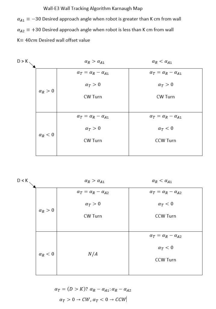
After letting this problem percolate for few days, I decided to see if I could approach the problem a little more logically. I realized there were two major conditions associated with the problem – namely is the robot’s initial position inside or outside the desired offset distance K? In addition, the robot can start out parallel to the wall, or pointed toward or away from the wall. Ignoring the ‘started out parallel’ degenerate case, this reminded me of a 3-parameter Karnaugh map configuration, so I started sketching it out in my notebook, and then later in a Word document, as shown below:

As shown above, I broke the 3-parameter into two 2-parameter Karnaugh maps, and the output is denoted by αT. After a few minutes it became obvious that the formula for αT is pretty simple – its either αR – αA1 or αR – αA2 depending on whether the robot starts out outside or inside the desired offset distance. In code, this boils down to one line, as shown at the bottom of the Karnaugh map above, using the C++ ‘?’ trinary operator, and choosing CW vs CCW is easy too, as a negative result implies CCW, and a positive one implies CW. The actual code block is shown below:
|
1 2 3 4 5 6 7 8 9 10 11 12 13 14 15 16 17 |
//Step3: now decide which way to turn. float turndeg = 0; float appAngle = 0; if (bInsideOffset) //approach angle = +30 { appAngle = 30; turndeg = WallOrientDeg - appAngle; fudgeFactorCm = -10; } else { appAngle = -30; turndeg = WallOrientDeg - appAngle; fudgeFactorCm = 10; } SpinTurn((turndeg < 0), abs(turndeg)); |
Here’s a short video of Wall-E3 navigating the office ‘sandbox’ while tracking the right-side wall.
So, it looks like Wall-E3 now has tracking ability for both left-side and right-side walls, although I still have to clean things up and port the simpler right-side code into TrackLeftWallOffset().
25 March 2022 Update:
Well, that was easy! I just got through porting the new right-side wall tracking algorithm over to TrackLeftWallOffset(), and right out of the box was able to demonstrate successful left-wall tracking in my office ‘sandbox’.
At this point I believe I’m going to consider the ‘WallE3_WallTrack_V3’ project ‘finished’ (in the sense that most, if not all, my wall tracking goals have been met with this version), and move on to V4, thereby limiting the possible damage from my next inevitable descent through the rabbit hole into wonderland.
Stay tuned,
Frank
