Opening port
Port open
Starting program, Scanning I2C addresses...
Scanning...
I2C device found at address 0x0C !
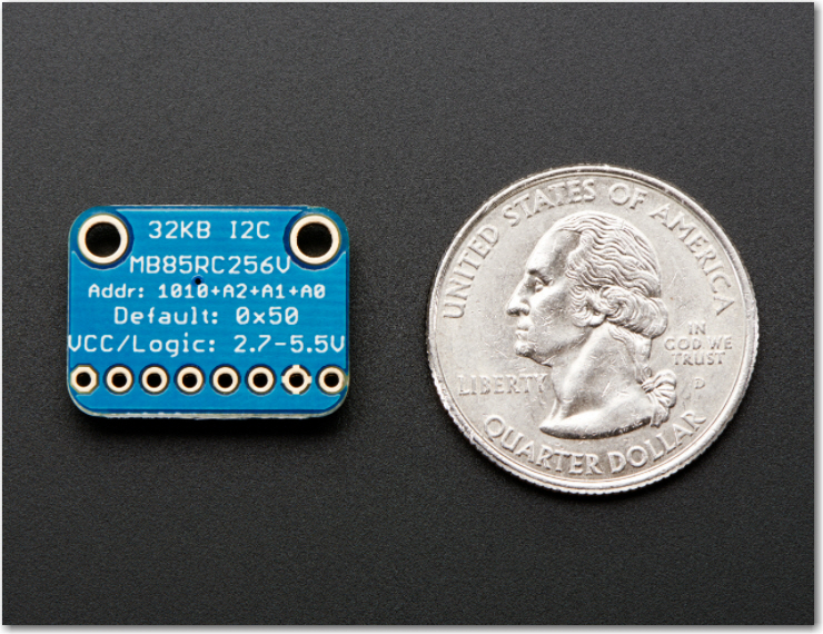
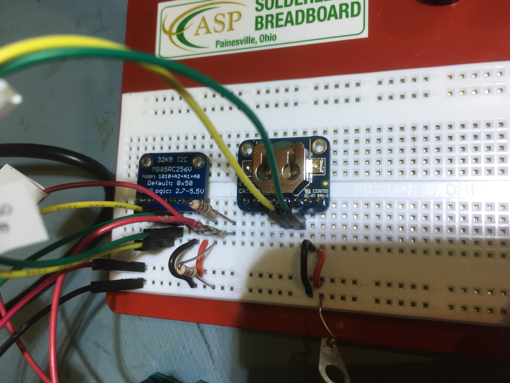
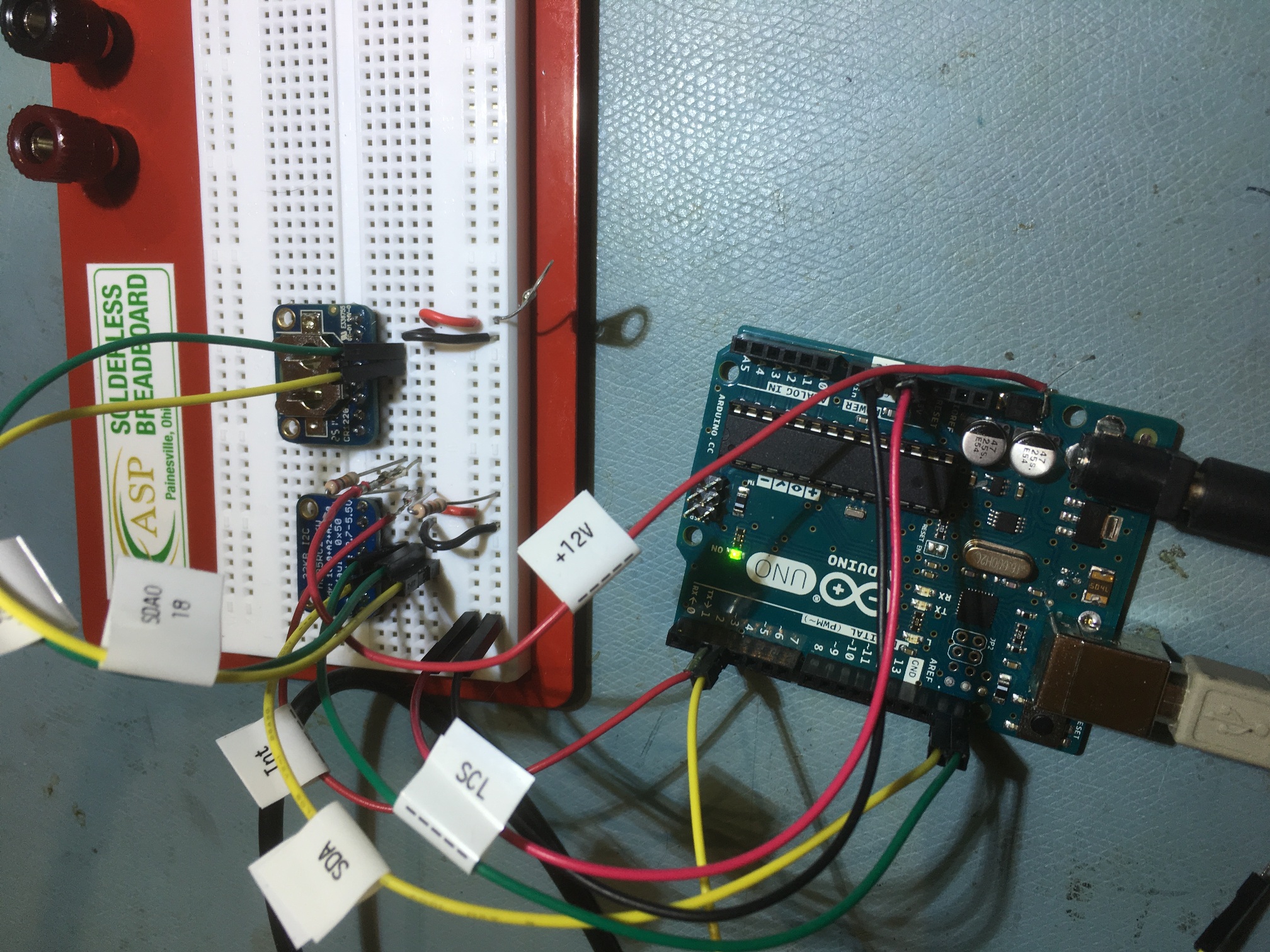
I2C device found at address 0x50 !
I2C device found at address 0x68 !
I2C device found at address 0x69 !
I2C device found at address 0x7C !
done
Initializing 9250 IMU...
MPU9250 I AM 71 I should be 71
MPU9250 is online - doing self-test...
Starting gyro/accel calibration - keep IMU motionless until finished...
gyro/accel calibration complete. Calibration took 381 Msec
MPU9250 initialized for active data mode....
Done...
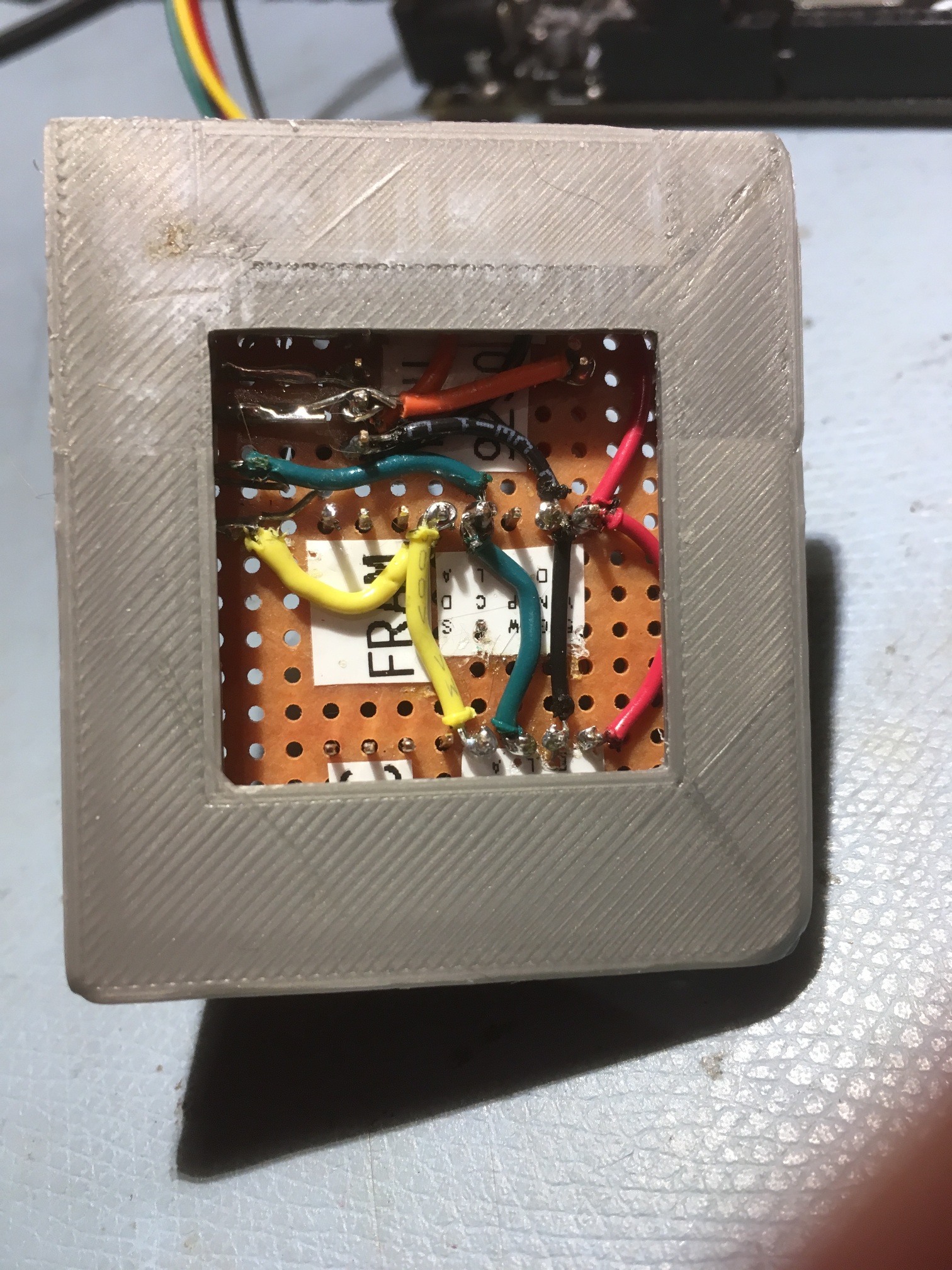
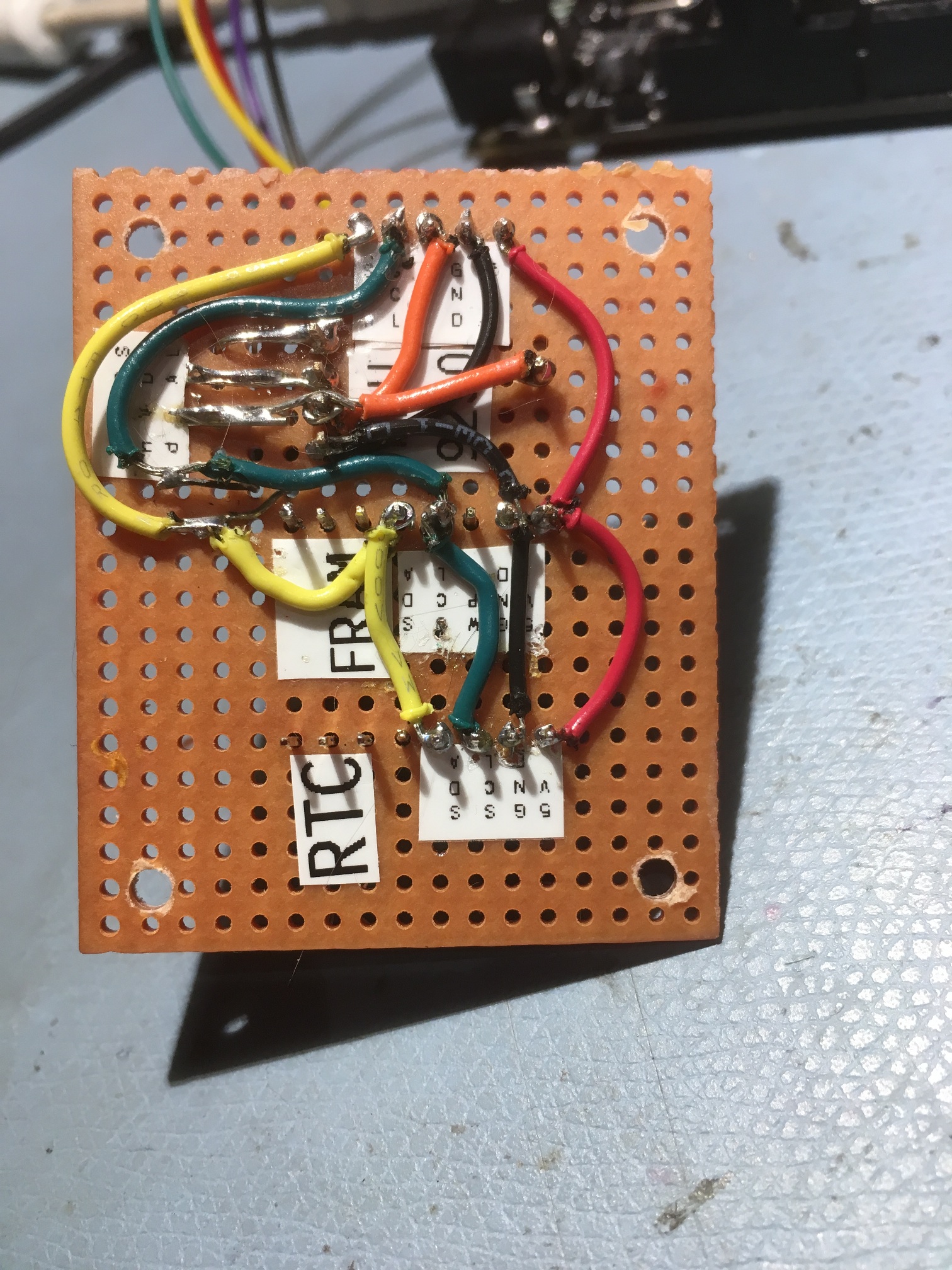
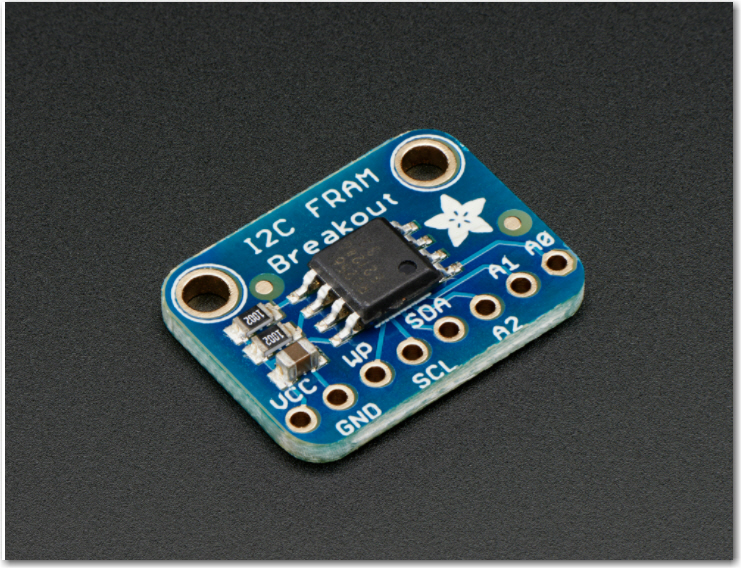
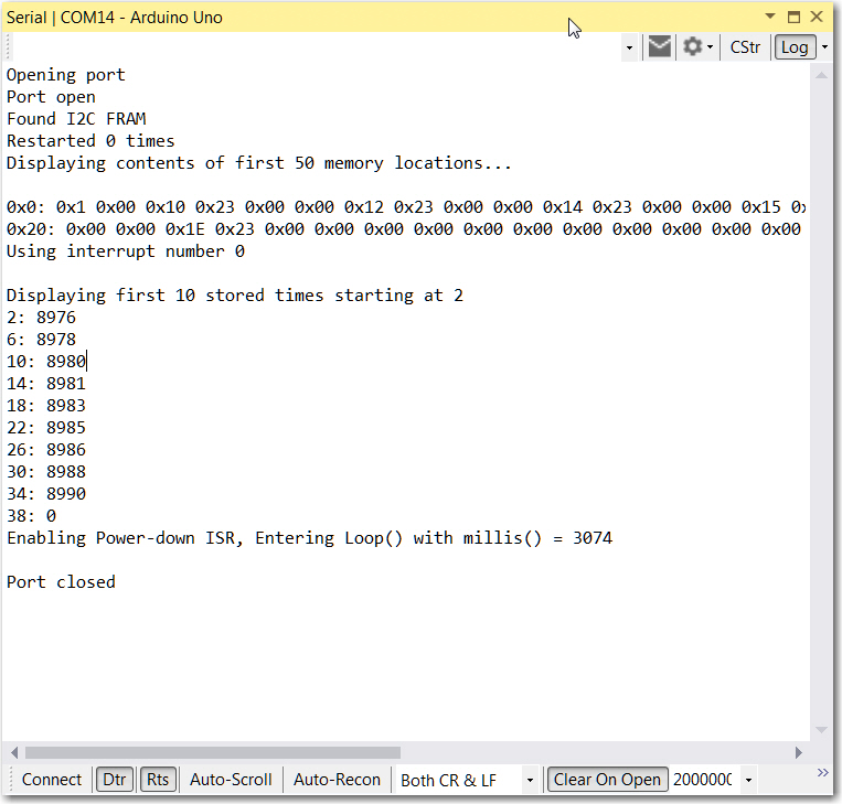
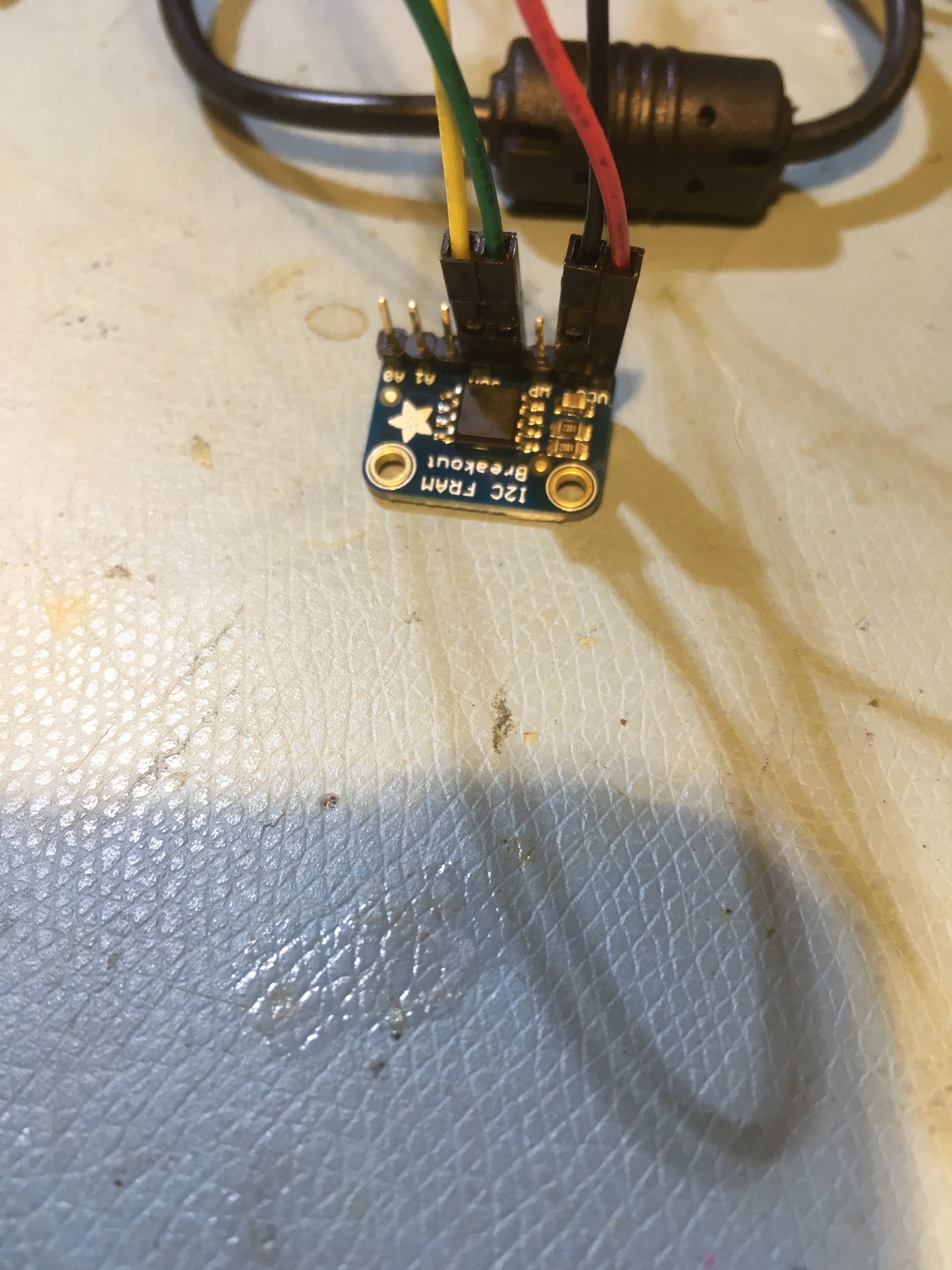
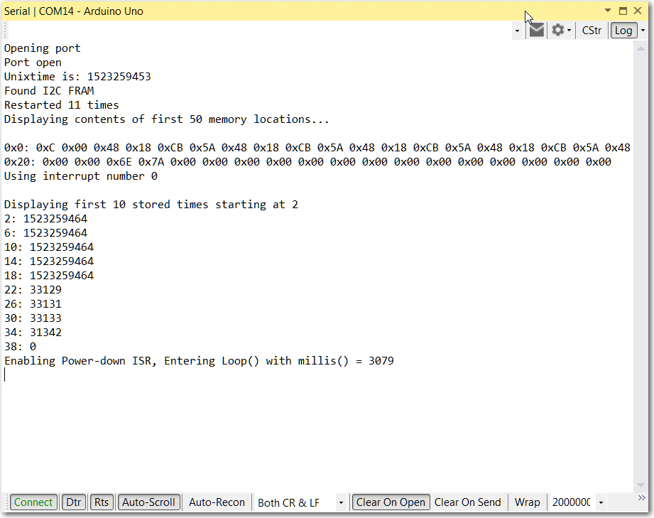
Found I2C FRAM
Restarted 8 times
Displaying contents of first 50 memory locations...
0x0: 0x9 0x00 0x00 0x00 0x00 0x00 0x00 0x00 0x00 0x00 0x00 0x00 0x00 0x00 0x00 0x00 0x00 0x00 0x00 0x00 0x00 0x00 0x00 0x00 0x00 0x00 0x00 0x00 0x00 0x00 0x00 0x00
0x20: 0x00 0x00 0x00 0x00 0x00 0xBE 0x00 0x00 0x00 0x00 0x00 0x00 0x00 0x00 0x00 0x00 0x00 0x00
In Loop()...
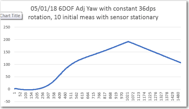
2018/5/6 (Sunday) 22:5:23 IMU Hdg = 21.79
2018/5/6 (Sunday) 22:5:23 IMU Hdg = 21.62
2018/5/6 (Sunday) 22:5:23 IMU Hdg = 21.42
2018/5/6 (Sunday) 22:5:23 IMU Hdg = 21.18
2018/5/6 (Sunday) 22:5:24 IMU Hdg = 20.93
2018/5/6 (Sunday) 22:5:24 IMU Hdg = 20.64
2018/5/6 (Sunday) 22:5:24 IMU Hdg = 20.33
2018/5/6 (Sunday) 22:5:24 IMU Hdg = 19.98
2018/5/6 (Sunday) 22:5:24 IMU Hdg = 19.57
2018/5/6 (Sunday) 22:5:25 IMU Hdg = 19.12
0x0: 0x9 0x00 0x00 0x3 0x00 0x00 0x00 0x00 0x00 0x00 0x00 0x00 0x00 0x00 0x00 0x00 0x00 0x00 0x00 0x00
2018/5/6 (Sunday) 22:5:25 IMU Hdg = 18.59
2018/5/6 (Sunday) 22:5:25 IMU Hdg = 18.02
2018/5/6 (Sunday) 22:5:25 IMU Hdg = 17.33
2018/5/6 (Sunday) 22:5:25 IMU Hdg = 16.59
2018/5/6 (Sunday) 22:5:26 IMU Hdg = 15.75
2018/5/6 (Sunday) 22:5:26 IMU Hdg = 14.84
2018/5/6 (Sunday) 22:5:26 IMU Hdg = 13.78
2018/5/6 (Sunday) 22:5:26 IMU Hdg = 12.59
2018/5/6 (Sunday) 22:5:26 IMU Hdg = 11.29
2018/5/6 (Sunday) 22:5:27 IMU Hdg = 9.86
0x0: 0x9 0x00 0x00 0x3 0x4 0x00 0x00 0x00 0x00 0x00 0x00 0x00 0x00 0x00 0x00 0x00 0x00 0x00 0x00 0x00
2018/5/6 (Sunday) 22:5:27 IMU Hdg = 8.32
2018/5/6 (Sunday) 22:5:27 IMU Hdg = 6.70
2018/5/6 (Sunday) 22:5:27 IMU Hdg = 5.00
2018/5/6 (Sunday) 22:5:27 IMU Hdg = 3.32
2018/5/6 (Sunday) 22:5:28 IMU Hdg = 1.71
2018/5/6 (Sunday) 22:5:28 IMU Hdg = 0.33
2018/5/6 (Sunday) 22:5:28 IMU Hdg = -0.70
2018/5/6 (Sunday) 22:5:28 IMU Hdg = -1.16
2018/5/6 (Sunday) 22:5:28 IMU Hdg = -0.92
2018/5/6 (Sunday) 22:5:29 IMU Hdg = -1.12
0x0: 0x9 0x00 0x00 0x3 0x4 0x5 0x00 0x00 0x00 0x00 0x00 0x00 0x00 0x00 0x00 0x00 0x00 0x00 0x00 0x00
2018/5/6 (Sunday) 22:5:29 IMU Hdg = -0.92
2018/5/6 (Sunday) 22:5:29 IMU Hdg = -1.06
2018/5/6 (Sunday) 22:5:29 IMU Hdg = -0.78
2018/5/6 (Sunday) 22:5:29 IMU Hdg = -1.03
2018/5/6 (Sunday) 22:5:30 IMU Hdg = -0.79
2018/5/6 (Sunday) 22:5:30 IMU Hdg = -1.01
2018/5/6 (Sunday) 22:5:30 IMU Hdg = -0.75
2018/5/6 (Sunday) 22:5:30 IMU Hdg = -0.94
2018/5/6 (Sunday) 22:5:30 IMU Hdg = -0.68
2018/5/6 (Sunday) 22:5:31 IMU Hdg = -0.93
0x0: 0x9 0x00 0x00 0x3 0x4 0x5 0x6 0x00 0x00 0x00 0x00 0x00 0x00 0x00 0x00 0x00 0x00 0x00 0x00 0x00
2018/5/6 (Sunday) 22:5:31 IMU Hdg = -0.66
2018/5/6 (Sunday) 22:5:31 IMU Hdg = -0.89
2018/5/6 (Sunday) 22:5:31 IMU Hdg = -0.62
2018/5/6 (Sunday) 22:5:31 IMU Hdg = -0.87
2018/5/6 (Sunday) 22:5:32 IMU Hdg = -0.62
2018/5/6 (Sunday) 22:5:32 IMU Hdg = -0.84
2018/5/6 (Sunday) 22:5:32 IMU Hdg = -0.62
2018/5/6 (Sunday) 22:5:32 IMU Hdg = -0.83
2018/5/6 (Sunday) 22:5:32 IMU Hdg = -0.62
2018/5/6 (Sunday) 22:5:33 IMU Hdg = -0.83
0x0: 0x9 0x00 0x00 0x3 0x4 0x5 0x6 0x7 0x00 0x00 0x00 0x00 0x00 0x00 0x00 0x00 0x00 0x00 0x00 0x00
2018/5/6 (Sunday) 22:5:33 IMU Hdg = -0.54
2018/5/6 (Sunday) 22:5:33 IMU Hdg = -0.80
2018/5/6 (Sunday) 22:5:33 IMU Hdg = -0.58
2018/5/6 (Sunday) 22:5:33 IMU Hdg = -0.76
2018/5/6 (Sunday) 22:5:34 IMU Hdg = -0.52
2018/5/6 (Sunday) 22:5:34 IMU Hdg = -0.73
2018/5/6 (Sunday) 22:5:34 IMU Hdg = -0.49
2018/5/6 (Sunday) 22:5:34 IMU Hdg = -0.70
2018/5/6 (Sunday) 22:5:34 IMU Hdg = -0.44
2018/5/6 (Sunday) 22:5:35 IMU Hdg = -0.69
0x0: 0x9 0x00 0x00 0x3 0x4 0x5 0x6 0x7 0x8 0x00 0x00 0x00 0x00 0x00 0x00 0x00 0x00 0x00 0x00 0x00
2018/5/6 (Sunday) 22:5:35 IMU Hdg = -0.45
2018/5/6 (Sunday) 22:5:35 IMU Hdg = -0.68
2018/5/6 (Sunday) 22:5:35 IMU Hdg = -0.39
2018/5/6 (Sunday) 22:5:35 IMU Hdg = -0.67
2018/5/6 (Sunday) 22:5:36 IMU Hdg = -0.43
2018/5/6 (Sunday) 22:5:36 IMU Hdg = -0.63
2018/5/6 (Sunday) 22:5:36 IMU Hdg = -0.36
2018/5/6 (Sunday) 22:5:36 IMU Hdg = -0.59
2018/5/6 (Sunday) 22:5:36 IMU Hdg = -0.36
2018/5/6 (Sunday) 22:5:37 IMU Hdg = -0.56
0x0: 0x9 0x00 0x00 0x3 0x4 0x5 0x6 0x7 0x8 0x9 0x00 0x00 0x00 0x00 0x00 0x00 0x00 0x00 0x00 0x00
2018/5/6 (Sunday) 22:5:37 IMU Hdg = -0.42
2018/5/6 (Sunday) 22:5:37 IMU Hdg = -0.57
2018/5/6 (Sunday) 22:5:37 IMU Hdg = -0.45
2018/5/6 (Sunday) 22:5:37 IMU Hdg = -0.56
2018/5/6 (Sunday) 22:5:38 IMU Hdg = -0.43
2018/5/6 (Sunday) 22:5:38 IMU Hdg = -0.52
2018/5/6 (Sunday) 22:5:38 IMU Hdg = -0.41
2018/5/6 (Sunday) 22:5:38 IMU Hdg = -0.49
2018/5/6 (Sunday) 22:5:38 IMU Hdg = -0.33
2018/5/6 (Sunday) 22:5:39 IMU Hdg = -0.44
0x0: 0x9 0x00 0x00 0x3 0x4 0x5 0x6 0x7 0x8 0x9 0xA 0x00 0x00 0x00 0x00 0x00 0x00 0x00 0x00 0x00
2018/5/6 (Sunday) 22:5:39 IMU Hdg = -0.32
2018/5/6 (Sunday) 22:5:39 IMU Hdg = -0.46
2018/5/6 (Sunday) 22:5:39 IMU Hdg = -0.41
2018/5/6 (Sunday) 22:5:39 IMU Hdg = -0.47
2018/5/6 (Sunday) 22:5:40 IMU Hdg = -0.42
2018/5/6 (Sunday) 22:5:40 IMU Hdg = -0.45
2018/5/6 (Sunday) 22:5:40 IMU Hdg = -0.45
2018/5/6 (Sunday) 22:5:40 IMU Hdg = -0.41
2018/5/6 (Sunday) 22:5:40 IMU Hdg = -0.37
2018/5/6 (Sunday) 22:5:41 IMU Hdg = -0.38
0x0: 0x9 0x00 0x00 0x3 0x4 0x5 0x6 0x7 0x8 0x9 0xA 0xB 0x00 0x00 0x00 0x00 0x00 0x00 0x00 0x00
2018/5/6 (Sunday) 22:5:41 IMU Hdg = -0.34
2018/5/6 (Sunday) 22:5:41 IMU Hdg = -0.37
2018/5/6 (Sunday) 22:5:41 IMU Hdg = -0.30
2018/5/6 (Sunday) 22:5:41 IMU Hdg = -0.35
2018/5/6 (Sunday) 22:5:42 IMU Hdg = -0.32
2018/5/6 (Sunday) 22:5:42 IMU Hdg = -0.33
2018/5/6 (Sunday) 22:5:42 IMU Hdg = -0.32
2018/5/6 (Sunday) 22:5:42 IMU Hdg = -0.32
2018/5/6 (Sunday) 22:5:42 IMU Hdg = -0.34
2018/5/6 (Sunday) 22:5:43 IMU Hdg = -0.32
0x0: 0x9 0x00 0x00 0x3 0x4 0x5 0x6 0x7 0x8 0x9 0xA 0xB 0xC 0x00 0x00 0x00 0x00 0x00 0x00 0x00
2018/5/6 (Sunday) 22:5:43 IMU Hdg = -0.34
2018/5/6 (Sunday) 22:5:43 IMU Hdg = -0.30
2018/5/6 (Sunday) 22:5:43 IMU Hdg = -0.37
2018/5/6 (Sunday) 22:5:43 IMU Hdg = -0.26
2018/5/6 (Sunday) 22:5:44 IMU Hdg = -0.29
2018/5/6 (Sunday) 22:5:44 IMU Hdg = -0.23
2018/5/6 (Sunday) 22:5:44 IMU Hdg = -0.34
2018/5/6 (Sunday) 22:5:44 IMU Hdg = -0.20
2018/5/6 (Sunday) 22:5:44 IMU Hdg = -0.28
2018/5/6 (Sunday) 22:5:45 IMU Hdg = -0.17
0x0: 0x9 0x00 0x00 0x3 0x4 0x5 0x6 0x7 0x8 0x9 0xA 0xB 0xC 0xD 0x00 0x00 0x00 0x00 0x00 0x00
2018/5/6 (Sunday) 22:5:45 IMU Hdg = -0.27
2018/5/6 (Sunday) 22:5:45 IMU Hdg = -0.15
2018/5/6 (Sunday) 22:5:45 IMU Hdg = -0.26
2018/5/6 (Sunday) 22:5:45 IMU Hdg = -0.12
2018/5/6 (Sunday) 22:5:46 IMU Hdg = -0.23
2018/5/6 (Sunday) 22:5:46 IMU Hdg = -0.08
2018/5/6 (Sunday) 22:5:46 IMU Hdg = -0.18
2018/5/6 (Sunday) 22:5:46 IMU Hdg = -0.10
2018/5/6 (Sunday) 22:5:46 IMU Hdg = -0.26
2018/5/6 (Sunday) 22:5:47 IMU Hdg = -0.09
0x0: 0x9 0x00 0x00 0x3 0x4 0x5 0x6 0x7 0x8 0x9 0xA 0xB 0xC 0xD 0xE 0x00 0x00 0x00 0x00 0x00
2018/5/6 (Sunday) 22:5:47 IMU Hdg = -0.26
2018/5/6 (Sunday) 22:5:47 IMU Hdg = -0.12
2018/5/6 (Sunday) 22:5:47 IMU Hdg = -0.35
2018/5/6 (Sunday) 22:5:47 IMU Hdg = -0.14
2018/5/6 (Sunday) 22:5:48 IMU Hdg = -0.39
2018/5/6 (Sunday) 22:5:48 IMU Hdg = -0.12
2018/5/6 (Sunday) 22:5:48 IMU Hdg = -0.34
2018/5/6 (Sunday) 22:5:48 IMU Hdg = -0.07
2018/5/6 (Sunday) 22:5:48 IMU Hdg = -0.33
2018/5/6 (Sunday) 22:5:49 IMU Hdg = -0.07
0x0: 0x9 0x00 0x00 0x3 0x4 0x5 0x6 0x7 0x8 0x9 0xA 0xB 0xC 0xD 0xE 0xF 0x00 0x00 0x00 0x00
2018/5/6 (Sunday) 22:5:49 IMU Hdg = -0.33
2018/5/6 (Sunday) 22:5:49 IMU Hdg = -0.02
2018/5/6 (Sunday) 22:5:49 IMU Hdg = -0.27
2018/5/6 (Sunday) 22:5:49 IMU Hdg = -0.01
2018/5/6 (Sunday) 22:5:50 IMU Hdg = -0.27
2018/5/6 (Sunday) 22:5:50 IMU Hdg = 0.00
2018/5/6 (Sunday) 22:5:50 IMU Hdg = -0.26
2018/5/6 (Sunday) 22:5:50 IMU Hdg = 0.04
2018/5/6 (Sunday) 22:5:50 IMU Hdg = -0.18
2018/5/6 (Sunday) 22:5:51 IMU Hdg = 0.09
0x0: 0x9 0x00 0x00 0x3 0x4 0x5 0x6 0x7 0x8 0x9 0xA 0xB 0xC 0xD 0xE 0xF 0x10 0x00 0x00 0x00
2018/5/6 (Sunday) 22:5:51 IMU Hdg = -0.16
2018/5/6 (Sunday) 22:5:51 IMU Hdg = 0.13
2018/5/6 (Sunday) 22:5:51 IMU Hdg = -0.15
2018/5/6 (Sunday) 22:5:51 IMU Hdg = 0.14
2018/5/6 (Sunday) 22:5:52 IMU Hdg = -0.12
2018/5/6 (Sunday) 22:5:52 IMU Hdg = 0.16
2018/5/6 (Sunday) 22:5:52 IMU Hdg = -0.11
2018/5/6 (Sunday) 22:5:52 IMU Hdg = 0.17
2018/5/6 (Sunday) 22:5:52 IMU Hdg = -0.11
2018/5/6 (Sunday) 22:5:53 IMU Hdg = 0.15
0x0: 0x9 0x00 0x00 0x3 0x4 0x5 0x6 0x7 0x8 0x9 0xA 0xB 0xC 0xD 0xE 0xF 0x10 0x11 0x00 0x00
2018/5/6 (Sunday) 22:5:53 IMU Hdg = -0.13
2018/5/6 (Sunday) 22:5:53 IMU Hdg = 0.18
2018/5/6 (Sunday) 22:5:53 IMU Hdg = -0.10
2018/5/6 (Sunday) 22:5:53 IMU Hdg = 0.23
2018/5/6 (Sunday) 22:5:54 IMU Hdg = -0.05
2018/5/6 (Sunday) 22:5:54 IMU Hdg = 0.26
2018/5/6 (Sunday) 22:5:54 IMU Hdg = -0.07
2018/5/6 (Sunday) 22:5:54 IMU Hdg = 0.26
2018/5/6 (Sunday) 22:5:54 IMU Hdg = -0.04
2018/5/6 (Sunday) 22:5:55 IMU Hdg = 0.25
0x0: 0x9 0x00 0x00 0x3 0x4 0x5 0x6 0x7 0x8 0x9 0xA 0xB 0xC 0xD 0xE 0xF 0x10 0x11 0x12 0x00
2018/5/6 (Sunday) 22:5:55 IMU Hdg = -0.05
2018/5/6 (Sunday) 22:5:55 IMU Hdg = 0.26
2018/5/6 (Sunday) 22:5:55 IMU Hdg = -0.01
2018/5/6 (Sunday) 22:5:55 IMU Hdg = 0.31
2018/5/6 (Sunday) 22:5:56 IMU Hdg = 0.03
2018/5/6 (Sunday) 22:5:56 IMU Hdg = 0.32
2018/5/6 (Sunday) 22:5:56 IMU Hdg = 0.02
2018/5/6 (Sunday) 22:5:56 IMU Hdg = 0.31
2018/5/6 (Sunday) 22:5:56 IMU Hdg = 0.04
2018/5/6 (Sunday) 22:5:57 IMU Hdg = 0.33
0x0: 0x9 0x00 0x00 0x3 0x4 0x5 0x6 0x7 0x8 0x9 0xA 0xB 0xC 0xD 0xE 0xF 0x10 0x11 0x12 0x13
2018/5/6 (Sunday) 22:5:57 IMU Hdg = 0.08
2018/5/6 (Sunday) 22:5:57 IMU Hdg = 0.35
2018/5/6 (Sunday) 22:5:57 IMU Hdg = 0.09
2018/5/6 (Sunday) 22:5:57 IMU Hdg = 0.38
2018/5/6 (Sunday) 22:5:58 IMU Hdg = 0.11
2018/5/6 (Sunday) 22:5:58 IMU Hdg = 0.37
2018/5/6 (Sunday) 22:5:58 IMU Hdg = 0.11
2018/5/6 (Sunday) 22:5:58 IMU Hdg = 0.40
2018/5/6 (Sunday) 22:5:58 IMU Hdg = 0.15
2018/5/6 (Sunday) 22:5:59 IMU Hdg = 0.41
0x0: 0x9 0x00 0x00 0x3 0x4 0x5 0x6 0x7 0x8 0x9 0xA 0xB 0xC 0xD 0xE 0xF 0x10 0x11 0x12 0x13
2018/5/6 (Sunday) 22:5:59 IMU Hdg = 0.16
2018/5/6 (Sunday) 22:5:59 IMU Hdg = 0.42
2018/5/6 (Sunday) 22:5:59 IMU Hdg = 0.18
2018/5/6 (Sunday) 22:5:59 IMU Hdg = 0.43
2018/5/6 (Sunday) 22:6:0 IMU Hdg = 0.19
2018/5/6 (Sunday) 22:6:0 IMU Hdg = 0.43
2018/5/6 (Sunday) 22:6:0 IMU Hdg = 0.22
2018/5/6 (Sunday) 22:6:0 IMU Hdg = 0.47
2018/5/6 (Sunday) 22:6:0 IMU Hdg = 0.24
2018/5/6 (Sunday) 22:6:1 IMU Hdg = 0.47
0x0: 0x9 0x00 0x00 0x3 0x4 0x5 0x6 0x7 0x8 0x9 0xA 0xB 0xC 0xD 0xE 0xF 0x10 0x11 0x12 0x13
2018/5/6 (Sunday) 22:6:1 IMU Hdg = 0.25
2018/5/6 (Sunday) 22:6:1 IMU Hdg = 0.49
2018/5/6 (Sunday) 22:6:1 IMU Hdg = 0.25
2018/5/6 (Sunday) 22:6:1 IMU Hdg = 0.47
2018/5/6 (Sunday) 22:6:2 IMU Hdg = 0.24
2018/5/6 (Sunday) 22:6:2 IMU Hdg = 0.52
2018/5/6 (Sunday) 22:6:2 IMU Hdg = 0.30
2018/5/6 (Sunday) 22:6:2 IMU Hdg = 0.52
2018/5/6 (Sunday) 22:6:2 IMU Hdg = 0.30
2018/5/6 (Sunday) 22:6:3 IMU Hdg = 0.52
0x0: 0x9 0x00 0x00 0x3 0x4 0x5 0x6 0x7 0x8 0x9 0xA 0xB 0xC 0xD 0xE 0xF 0x10 0x11 0x12 0x00
2018/5/6 (Sunday) 22:6:3 IMU Hdg = 0.33
2018/5/6 (Sunday) 22:6:3 IMU Hdg = 0.52
2018/5/6 (Sunday) 22:6:3 IMU Hdg = 0.33
2018/5/6 (Sunday) 22:6:3 IMU Hdg = 0.53
2018/5/6 (Sunday) 22:6:4 IMU Hdg = 0.33
2018/5/6 (Sunday) 22:6:4 IMU Hdg = 0.54
2018/5/6 (Sunday) 22:6:4 IMU Hdg = 0.36
2018/5/6 (Sunday) 22:6:4 IMU Hdg = 0.56
2018/5/6 (Sunday) 22:6:4 IMU Hdg = 0.39
2018/5/6 (Sunday) 22:6:5 IMU Hdg = 0.59
0x0: 0x9 0x00 0x00 0x3 0x4 0x5 0x6 0x7 0x8 0x9 0xA 0xB 0xC 0xD 0xE 0xF 0x10 0x11 0x00 0x00
2018/5/6 (Sunday) 22:6:5 IMU Hdg = 0.43
2018/5/6 (Sunday) 22:6:5 IMU Hdg = 0.64
2018/5/6 (Sunday) 22:6:5 IMU Hdg = 0.48
2018/5/6 (Sunday) 22:6:5 IMU Hdg = 0.65
2018/5/6 (Sunday) 22:6:6 IMU Hdg = 0.52
2018/5/6 (Sunday) 22:6:6 IMU Hdg = 0.73
2018/5/6 (Sunday) 22:6:6 IMU Hdg = 0.60
2018/5/6 (Sunday) 22:6:6 IMU Hdg = 0.77
2018/5/6 (Sunday) 22:6:6 IMU Hdg = 0.64
2018/5/6 (Sunday) 22:6:7 IMU Hdg = 0.80
0x0: 0x9 0x00 0x00 0x3 0x4 0x5 0x6 0x7 0x8 0x9 0xA 0xB 0xC 0xD 0xE 0xF 0x10 0x00 0x00 0x00
2018/5/6 (Sunday) 22:6:7 IMU Hdg = 0.66
2018/5/6 (Sunday) 22:6:7 IMU Hdg = 0.80
2018/5/6 (Sunday) 22:6:7 IMU Hdg = 0.69
2018/5/6 (Sunday) 22:6:7 IMU Hdg = 0.81
2018/5/6 (Sunday) 22:6:8 IMU Hdg = 0.69
2018/5/6 (Sunday) 22:6:8 IMU Hdg = 0.85
2018/5/6 (Sunday) 22:6:8 IMU Hdg = 0.73
2018/5/6 (Sunday) 22:6:8 IMU Hdg = 0.85
2018/5/6 (Sunday) 22:6:8 IMU Hdg = 0.76
2018/5/6 (Sunday) 22:6:9 IMU Hdg = 0.88
0x0: 0x9 0x00 0x00 0x3 0x4 0x5 0x6 0x7 0x8 0x9 0xA 0xB 0xC 0xD 0xE 0xF 0x00 0x00 0x00 0x00
2018/5/6 (Sunday) 22:6:9 IMU Hdg = 0.80
2018/5/6 (Sunday) 22:6:9 IMU Hdg = 0.91
2018/5/6 (Sunday) 22:6:9 IMU Hdg = 0.81
2018/5/6 (Sunday) 22:6:9 IMU Hdg = 0.91
2018/5/6 (Sunday) 22:6:10 IMU Hdg = 0.82
2018/5/6 (Sunday) 22:6:10 IMU Hdg = 0.93
2018/5/6 (Sunday) 22:6:10 IMU Hdg = 0.84
2018/5/6 (Sunday) 22:6:10 IMU Hdg = 0.92
2018/5/6 (Sunday) 22:6:10 IMU Hdg = 0.82
2018/5/6 (Sunday) 22:6:11 IMU Hdg = 0.94
0x0: 0x9 0x00 0x00 0x3 0x4 0x5 0x6 0x7 0x8 0x9 0xA 0xB 0xC 0xD 0xE 0x00 0x00 0x00 0x00 0x00
2018/5/6 (Sunday) 22:6:11 IMU Hdg = 0.83
2018/5/6 (Sunday) 22:6:11 IMU Hdg = 0.92
2018/5/6 (Sunday) 22:6:11 IMU Hdg = 0.83
2018/5/6 (Sunday) 22:6:11 IMU Hdg = 0.94
2018/5/6 (Sunday) 22:6:12 IMU Hdg = 0.87
2018/5/6 (Sunday) 22:6:12 IMU Hdg = 0.96
2018/5/6 (Sunday) 22:6:12 IMU Hdg = 0.89
2018/5/6 (Sunday) 22:6:12 IMU Hdg = 0.98
2018/5/6 (Sunday) 22:6:12 IMU Hdg = 0.94
2018/5/6 (Sunday) 22:6:13 IMU Hdg = 0.99
0x0: 0x9 0x00 0x00 0x3 0x4 0x5 0x6 0x7 0x8 0x9 0xA 0xB 0xC 0xD 0x00 0x00 0x00 0x00 0x00 0x00
2018/5/6 (Sunday) 22:6:13 IMU Hdg = 0.91
2018/5/6 (Sunday) 22:6:13 IMU Hdg = 0.97
2018/5/6 (Sunday) 22:6:13 IMU Hdg = 0.91
2018/5/6 (Sunday) 22:6:13 IMU Hdg = 0.99
2018/5/6 (Sunday) 22:6:14 IMU Hdg = 0.96
2018/5/6 (Sunday) 22:6:14 IMU Hdg = 1.01
2018/5/6 (Sunday) 22:6:14 IMU Hdg = 0.98
2018/5/6 (Sunday) 22:6:14 IMU Hdg = 1.02
2018/5/6 (Sunday) 22:6:14 IMU Hdg = 0.95
2018/5/6 (Sunday) 22:6:15 IMU Hdg = 0.99
0x0: 0x9 0x00 0x00 0x3 0x4 0x5 0x6 0x7 0x8 0x9 0xA 0xB 0xC 0x00 0x00 0x00 0x00 0x00 0x00 0x00
2018/5/6 (Sunday) 22:6:15 IMU Hdg = 0.99
2018/5/6 (Sunday) 22:6:15 IMU Hdg = 1.04
2018/5/6 (Sunday) 22:6:15 IMU Hdg = 1.00
2018/5/6 (Sunday) 22:6:15 IMU Hdg = 1.05
2018/5/6 (Sunday) 22:6:16 IMU Hdg = 1.07
2018/5/6 (Sunday) 22:6:16 IMU Hdg = 1.07
2018/5/6 (Sunday) 22:6:16 IMU Hdg = 1.04
2018/5/6 (Sunday) 22:6:16 IMU Hdg = 1.08
2018/5/6 (Sunday) 22:6:16 IMU Hdg = 1.07
2018/5/6 (Sunday) 22:6:17 IMU Hdg = 1.10
0x0: 0x9 0x00 0x00 0x3 0x4 0x5 0x6 0x7 0x8 0x9 0xA 0xB 0x00 0x00 0x00 0x00 0x00 0x00 0x00 0x00
2018/5/6 (Sunday) 22:6:17 IMU Hdg = 1.09
2018/5/6 (Sunday) 22:6:17 IMU Hdg = 1.12
2018/5/6 (Sunday) 22:6:17 IMU Hdg = 1.13
2018/5/6 (Sunday) 22:6:17 IMU Hdg = 1.14
2018/5/6 (Sunday) 22:6:18 IMU Hdg = 1.17
2018/5/6 (Sunday) 22:6:18 IMU Hdg = 1.18
2018/5/6 (Sunday) 22:6:18 IMU Hdg = 1.20
2018/5/6 (Sunday) 22:6:18 IMU Hdg = 1.18
2018/5/6 (Sunday) 22:6:18 IMU Hdg = 1.21
2018/5/6 (Sunday) 22:6:19 IMU Hdg = 1.20
0x0: 0x9 0x00 0x00 0x3 0x4 0x5 0x6 0x7 0x8 0x9 0xA 0x00 0x00 0x00 0x00 0x00 0x00 0x00 0x00 0x00
2018/5/6 (Sunday) 22:6:19 IMU Hdg = 1.25
2018/5/6 (Sunday) 22:6:19 IMU Hdg = 1.22
2018/5/6 (Sunday) 22:6:19 IMU Hdg = 1.27
2018/5/6 (Sunday) 22:6:19 IMU Hdg = 1.26
2018/5/6 (Sunday) 22:6:20 IMU Hdg = 1.32
2018/5/6 (Sunday) 22:6:20 IMU Hdg = 1.27
2018/5/6 (Sunday) 22:6:20 IMU Hdg = 1.33
2018/5/6 (Sunday) 22:6:20 IMU Hdg = 1.28
2018/5/6 (Sunday) 22:6:20 IMU Hdg = 1.34
2018/5/6 (Sunday) 22:6:21 IMU Hdg = 1.31
0x0: 0x9 0x00 0x00 0x3 0x4 0x5 0x6 0x7 0x8 0x9 0x00 0x00 0x00 0x00 0x00 0x00 0x00 0x00 0x00 0x00
2018/5/6 (Sunday) 22:6:21 IMU Hdg = 1.36
2018/5/6 (Sunday) 22:6:21 IMU Hdg = 1.33
2018/5/6 (Sunday) 22:6:21 IMU Hdg = 1.39
2018/5/6 (Sunday) 22:6:21 IMU Hdg = 1.33
2018/5/6 (Sunday) 22:6:22 IMU Hdg = 1.39
2018/5/6 (Sunday) 22:6:22 IMU Hdg = 1.32
2018/5/6 (Sunday) 22:6:22 IMU Hdg = 1.39
2018/5/6 (Sunday) 22:6:22 IMU Hdg = 1.33
2018/5/6 (Sunday) 22:6:22 IMU Hdg = 1.41
2018/5/6 (Sunday) 22:6:23 IMU Hdg = 1.36
0x0: 0x9 0x00 0x00 0x3 0x4 0x5 0x6 0x7 0x8 0x00 0x00 0x00 0x00 0x00 0x00 0x00 0x00 0x00 0x00 0x00
2018/5/6 (Sunday) 22:6:23 IMU Hdg = 1.45
2018/5/6 (Sunday) 22:6:23 IMU Hdg = 1.38
2018/5/6 (Sunday) 22:6:23 IMU Hdg = 1.48
2018/5/6 (Sunday) 22:6:23 IMU Hdg = 1.39
2018/5/6 (Sunday) 22:6:24 IMU Hdg = 1.45
2018/5/6 (Sunday) 22:6:24 IMU Hdg = 1.39
2018/5/6 (Sunday) 22:6:24 IMU Hdg = 1.48
2018/5/6 (Sunday) 22:6:24 IMU Hdg = 1.40
2018/5/6 (Sunday) 22:6:24 IMU Hdg = 1.54
2018/5/6 (Sunday) 22:6:25 IMU Hdg = 1.44
0x0: 0x9 0x00 0x00 0x3 0x4 0x5 0x6 0x7 0x00 0x00 0x00 0x00 0x00 0x00 0x00 0x00 0x00 0x00 0x00 0x00
2018/5/6 (Sunday) 22:6:25 IMU Hdg = 1.54
2018/5/6 (Sunday) 22:6:25 IMU Hdg = 1.44
2018/5/6 (Sunday) 22:6:25 IMU Hdg = 1.59
2018/5/6 (Sunday) 22:6:25 IMU Hdg = 1.49
2018/5/6 (Sunday) 22:6:26 IMU Hdg = 1.61
2018/5/6 (Sunday) 22:6:26 IMU Hdg = 1.48
2018/5/6 (Sunday) 22:6:26 IMU Hdg = 1.61
2018/5/6 (Sunday) 22:6:26 IMU Hdg = 1.48
2018/5/6 (Sunday) 22:6:26 IMU Hdg = 1.62
2018/5/6 (Sunday) 22:6:27 IMU Hdg = 1.47
0x0: 0x9 0x00 0x00 0x3 0x4 0x5 0x6 0x00 0x00 0x00 0x00 0x00 0x00 0x00 0x00 0x00 0x00 0x00 0x00 0x00
2018/5/6 (Sunday) 22:6:27 IMU Hdg = 1.64
2018/5/6 (Sunday) 22:6:27 IMU Hdg = 1.51
2018/5/6 (Sunday) 22:6:27 IMU Hdg = 1.65
2018/5/6 (Sunday) 22:6:27 IMU Hdg = 1.50
2018/5/6 (Sunday) 22:6:28 IMU Hdg = 1.64
2018/5/6 (Sunday) 22:6:28 IMU Hdg = 1.50
2018/5/6 (Sunday) 22:6:28 IMU Hdg = 1.68
2018/5/6 (Sunday) 22:6:28 IMU Hdg = 1.52
2018/5/6 (Sunday) 22:6:28 IMU Hdg = 1.71
2018/5/6 (Sunday) 22:6:29 IMU Hdg = 1.55
0x0: 0x9 0x00 0x00 0x3 0x4 0x5 0x00 0x00 0x00 0x00 0x00 0x00 0x00 0x00 0x00 0x00 0x00 0x00 0x00 0x00
2018/5/6 (Sunday) 22:6:29 IMU Hdg = 1.74
2018/5/6 (Sunday) 22:6:29 IMU Hdg = 1.59
2018/5/6 (Sunday) 22:6:29 IMU Hdg = 1.77
2018/5/6 (Sunday) 22:6:29 IMU Hdg = 1.62
2018/5/6 (Sunday) 22:6:30 IMU Hdg = 1.82
2018/5/6 (Sunday) 22:6:30 IMU Hdg = 1.65
2018/5/6 (Sunday) 22:6:30 IMU Hdg = 1.82
2018/5/6 (Sunday) 22:6:30 IMU Hdg = 1.72
2018/5/6 (Sunday) 22:6:30 IMU Hdg = 1.89
2018/5/6 (Sunday) 22:6:31 IMU Hdg = 1.74
0x0: 0x9 0x00 0x00 0x3 0x4 0x00 0x00 0x00 0x00 0x00 0x00 0x00 0x00 0x00 0x00 0x00 0x00 0x00 0x00 0x00
2018/5/6 (Sunday) 22:6:31 IMU Hdg = 1.95
2018/5/6 (Sunday) 22:6:31 IMU Hdg = 1.81
2018/5/6 (Sunday) 22:6:31 IMU Hdg = 1.97
2018/5/6 (Sunday) 22:6:31 IMU Hdg = 1.87
2018/5/6 (Sunday) 22:6:32 IMU Hdg = 2.04
2018/5/6 (Sunday) 22:6:32 IMU Hdg = 1.88
2018/5/6 (Sunday) 22:6:32 IMU Hdg = 2.06
2018/5/6 (Sunday) 22:6:32 IMU Hdg = 1.93
2018/5/6 (Sunday) 22:6:32 IMU Hdg = 2.07
2018/5/6 (Sunday) 22:6:33 IMU Hdg = 1.95
0x0: 0x9 0x00 0x00 0x3 0x00 0x00 0x00 0x00 0x00 0x00 0x00 0x00 0x00 0x00 0x00 0x00 0x00 0x00 0x00 0x00
2018/5/6 (Sunday) 22:6:33 IMU Hdg = 2.11
2018/5/6 (Sunday) 22:6:33 IMU Hdg = 1.96
2018/5/6 (Sunday) 22:6:33 IMU Hdg = 2.11
2018/5/6 (Sunday) 22:6:33 IMU Hdg = 1.97
2018/5/6 (Sunday) 22:6:34 IMU Hdg = 2.11
2018/5/6 (Sunday) 22:6:34 IMU Hdg = 1.97
2018/5/6 (Sunday) 22:6:34 IMU Hdg = 2.11
2018/5/6 (Sunday) 22:6:34 IMU Hdg = 1.93
2018/5/6 (Sunday) 22:6:34 IMU Hdg = 2.14
2018/5/6 (Sunday) 22:6:35 IMU Hdg = 2.01
0x0: 0x9 0x00 0x00 0x00 0x00 0x00 0x00 0x00 0x00 0x00 0x00 0x00 0x00 0x00 0x00 0x00 0x00 0x00 0x00 0x00
2018/5/6 (Sunday) 22:6:35 IMU Hdg = 2.17
2018/5/6 (Sunday) 22:6:35 IMU Hdg = 2.00
2018/5/6 (Sunday) 22:6:35 IMU Hdg = 2.21
2018/5/6 (Sunday) 22:6:35 IMU Hdg = 2.09
2018/5/6 (Sunday) 22:6:36 IMU Hdg = 2.26
2018/5/6 (Sunday) 22:6:36 IMU Hdg = 2.13
2018/5/6 (Sunday) 22:6:36 IMU Hdg = 2.27
2018/5/6 (Sunday) 22:6:36 IMU Hdg = 2.09
2018/5/6 (Sunday) 22:6:36 IMU Hdg = 2.30
2018/5/6 (Sunday) 22:6:37 IMU Hdg = 2.12
0x0: 0x9 0x00 0x00 0x3 0x00 0x00 0x00 0x00 0x00 0x00 0x00 0x00 0x00 0x00 0x00 0x00 0x00 0x00 0x00 0x00
2018/5/6 (Sunday) 22:6:37 IMU Hdg = 2.32
2018/5/6 (Sunday) 22:6:37 IMU Hdg = 2.17
2018/5/6 (Sunday) 22:6:37 IMU Hdg = 2.38
2018/5/6 (Sunday) 22:6:37 IMU Hdg = 2.27
2018/5/6 (Sunday) 22:6:38 IMU Hdg = 2.41
2018/5/6 (Sunday) 22:6:38 IMU Hdg = 2.29
2018/5/6 (Sunday) 22:6:38 IMU Hdg = 2.45
2018/5/6 (Sunday) 22:6:38 IMU Hdg = 2.31
2018/5/6 (Sunday) 22:6:38 IMU Hdg = 2.49
2018/5/6 (Sunday) 22:6:39 IMU Hdg = 2.32
0x0: 0x9 0x00 0x00 0x3 0x4 0x00 0x00 0x00 0x00 0x00 0x00 0x00 0x00 0x00 0x00 0x00 0x00 0x00 0x00 0x00
2018/5/6 (Sunday) 22:6:39 IMU Hdg = 2.49
2018/5/6 (Sunday) 22:6:39 IMU Hdg = 2.34
2018/5/6 (Sunday) 22:6:39 IMU Hdg = 2.52
2018/5/6 (Sunday) 22:6:39 IMU Hdg = 2.37
2018/5/6 (Sunday) 22:6:40 IMU Hdg = 2.56
2018/5/6 (Sunday) 22:6:40 IMU Hdg = 2.46
2018/5/6 (Sunday) 22:6:40 IMU Hdg = 2.59
2018/5/6 (Sunday) 22:6:40 IMU Hdg = 2.45
2018/5/6 (Sunday) 22:6:40 IMU Hdg = 2.61
2018/5/6 (Sunday) 22:6:41 IMU Hdg = 2.51
0x0: 0x9 0x00 0x00 0x3 0x4 0x5 0x00 0x00 0x00 0x00 0x00 0x00 0x00 0x00 0x00 0x00 0x00 0x00 0x00 0x00
2018/5/6 (Sunday) 22:6:41 IMU Hdg = 2.64
2018/5/6 (Sunday) 22:6:41 IMU Hdg = 2.50
2018/5/6 (Sunday) 22:6:41 IMU Hdg = 2.64
2018/5/6 (Sunday) 22:6:41 IMU Hdg = 2.48
2018/5/6 (Sunday) 22:6:42 IMU Hdg = 2.67
2018/5/6 (Sunday) 22:6:42 IMU Hdg = 2.58
2018/5/6 (Sunday) 22:6:42 IMU Hdg = 2.71
2018/5/6 (Sunday) 22:6:42 IMU Hdg = 2.61
2018/5/6 (Sunday) 22:6:42 IMU Hdg = 2.72
2018/5/6 (Sunday) 22:6:43 IMU Hdg = 2.62
0x0: 0x9 0x00 0x00 0x3 0x4 0x5 0x6 0x00 0x00 0x00 0x00 0x00 0x00 0x00 0x00 0x00 0x00 0x00 0x00 0x00
2018/5/6 (Sunday) 22:6:43 IMU Hdg = 2.73
2018/5/6 (Sunday) 22:6:43 IMU Hdg = 2.64
2018/5/6 (Sunday) 22:6:43 IMU Hdg = 2.75
2018/5/6 (Sunday) 22:6:43 IMU Hdg = 2.61
2018/5/6 (Sunday) 22:6:44 IMU Hdg = 2.76
2018/5/6 (Sunday) 22:6:44 IMU Hdg = 2.57
2018/5/6 (Sunday) 22:6:44 IMU Hdg = 2.74
2018/5/6 (Sunday) 22:6:44 IMU Hdg = 2.57
2018/5/6 (Sunday) 22:6:44 IMU Hdg = 2.74
2018/5/6 (Sunday) 22:6:45 IMU Hdg = 2.55
0x0: 0x9 0x00 0x00 0x3 0x4 0x5 0x6 0x7 0x00 0x00 0x00 0x00 0x00 0x00 0x00 0x00 0x00 0x00 0x00 0x00
2018/5/6 (Sunday) 22:6:45 IMU Hdg = 2.73
2018/5/6 (Sunday) 22:6:45 IMU Hdg = 2.58
2018/5/6 (Sunday) 22:6:45 IMU Hdg = 2.78
2018/5/6 (Sunday) 22:6:45 IMU Hdg = 2.65
2018/5/6 (Sunday) 22:6:46 IMU Hdg = 2.80
2018/5/6 (Sunday) 22:6:46 IMU Hdg = 2.67
2018/5/6 (Sunday) 22:6:46 IMU Hdg = 2.82
2018/5/6 (Sunday) 22:6:46 IMU Hdg = 2.73
2018/5/6 (Sunday) 22:6:46 IMU Hdg = 2.85
2018/5/6 (Sunday) 22:6:47 IMU Hdg = 2.76
0x0: 0x9 0x00 0x00 0x3 0x4 0x5 0x6 0x7 0x8 0x00 0x00 0x00 0x00 0x00 0x00 0x00 0x00 0x00 0x00 0x00
2018/5/6 (Sunday) 22:6:47 IMU Hdg = 2.91
2018/5/6 (Sunday) 22:6:47 IMU Hdg = 2.79
2018/5/6 (Sunday) 22:6:47 IMU Hdg = 2.95
2018/5/6 (Sunday) 22:6:47 IMU Hdg = 2.86
2018/5/6 (Sunday) 22:6:48 IMU Hdg = 3.00
2018/5/6 (Sunday) 22:6:48 IMU Hdg = 2.90
2018/5/6 (Sunday) 22:6:48 IMU Hdg = 3.03
2018/5/6 (Sunday) 22:6:48 IMU Hdg = 2.95
2018/5/6 (Sunday) 22:6:48 IMU Hdg = 3.05
2018/5/6 (Sunday) 22:6:49 IMU Hdg = 2.99
0x0: 0x9 0x00 0x00 0x3 0x4 0x5 0x6 0x7 0x8 0x9 0x00 0x00 0x00 0x00 0x00 0x00 0x00 0x00 0x00 0x00
2018/5/6 (Sunday) 22:6:49 IMU Hdg = 3.08
2018/5/6 (Sunday) 22:6:49 IMU Hdg = 3.06
2018/5/6 (Sunday) 22:6:49 IMU Hdg = 3.11
2018/5/6 (Sunday) 22:6:49 IMU Hdg = 3.07
2018/5/6 (Sunday) 22:6:50 IMU Hdg = 3.09
2018/5/6 (Sunday) 22:6:50 IMU Hdg = 3.07
2018/5/6 (Sunday) 22:6:50 IMU Hdg = 3.13
2018/5/6 (Sunday) 22:6:50 IMU Hdg = 3.08
2018/5/6 (Sunday) 22:6:50 IMU Hdg = 3.11
2018/5/6 (Sunday) 22:6:51 IMU Hdg = 3.05
0x0: 0x9 0x00 0x00 0x3 0x4 0x5 0x6 0x7 0x8 0x9 0xA 0x00 0x00 0x00 0x00 0x00 0x00 0x00 0x00 0x00
2018/5/6 (Sunday) 22:6:51 IMU Hdg = 3.13
2018/5/6 (Sunday) 22:6:51 IMU Hdg = 3.07
2018/5/6 (Sunday) 22:6:51 IMU Hdg = 3.18
2018/5/6 (Sunday) 22:6:51 IMU Hdg = 3.10
2018/5/6 (Sunday) 22:6:52 IMU Hdg = 3.20
2018/5/6 (Sunday) 22:6:52 IMU Hdg = 3.13
2018/5/6 (Sunday) 22:6:52 IMU Hdg = 3.26
Port closed