Posted 13 October 2019
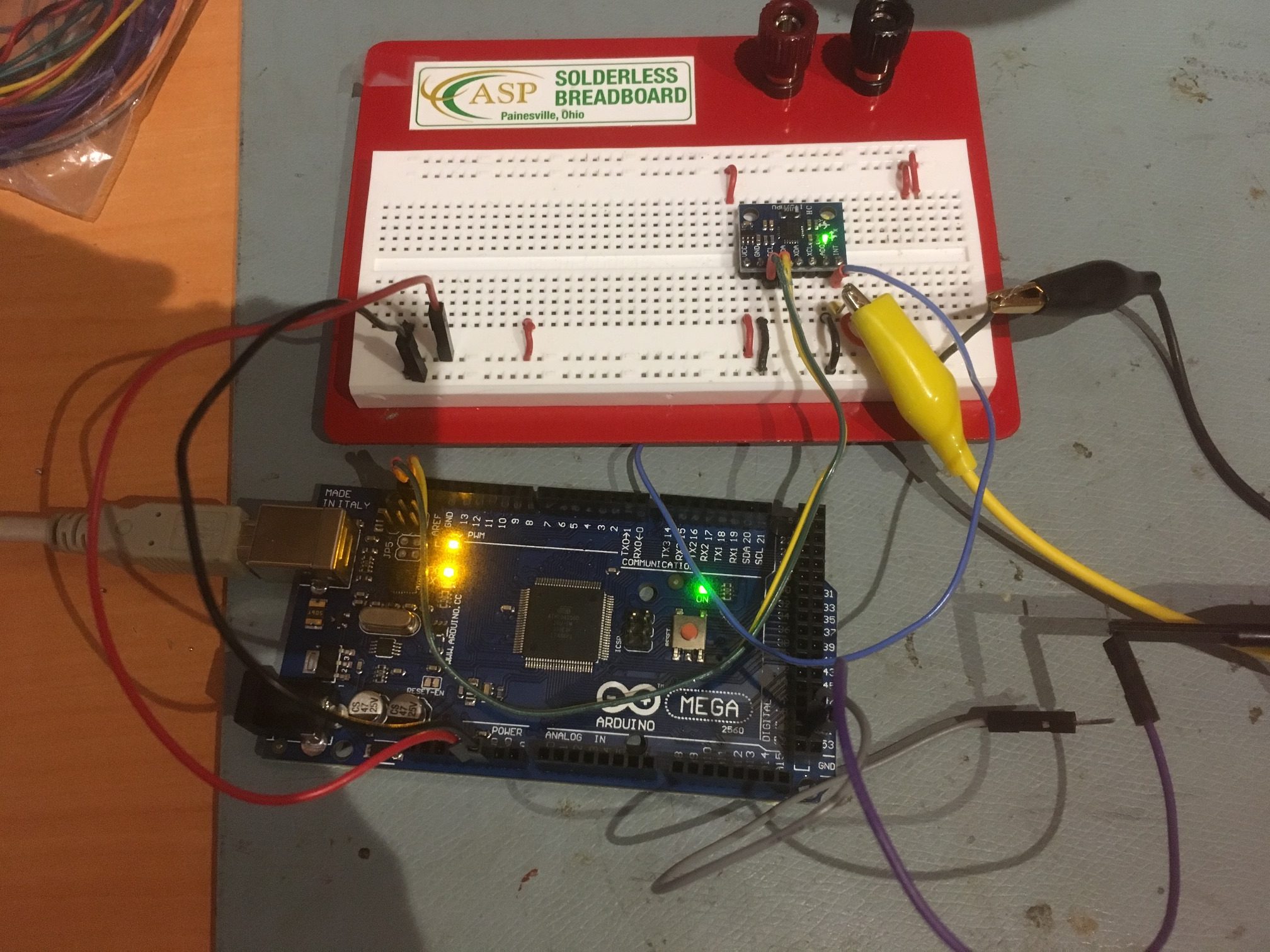
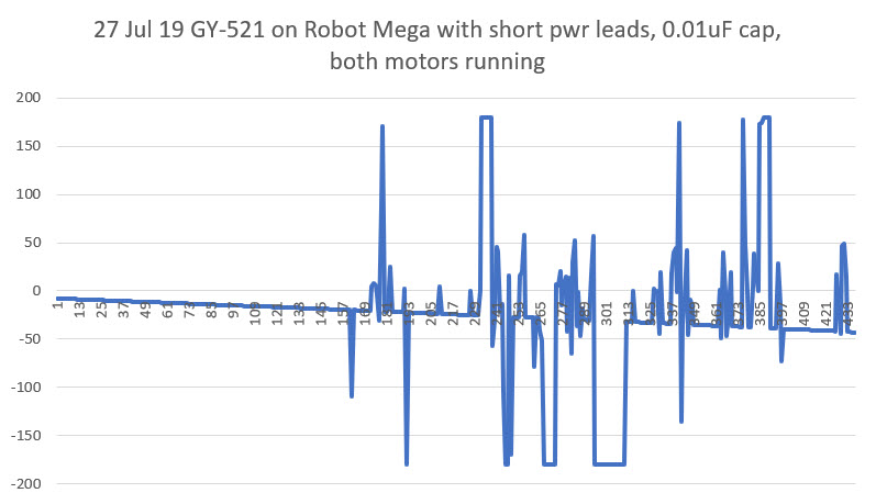
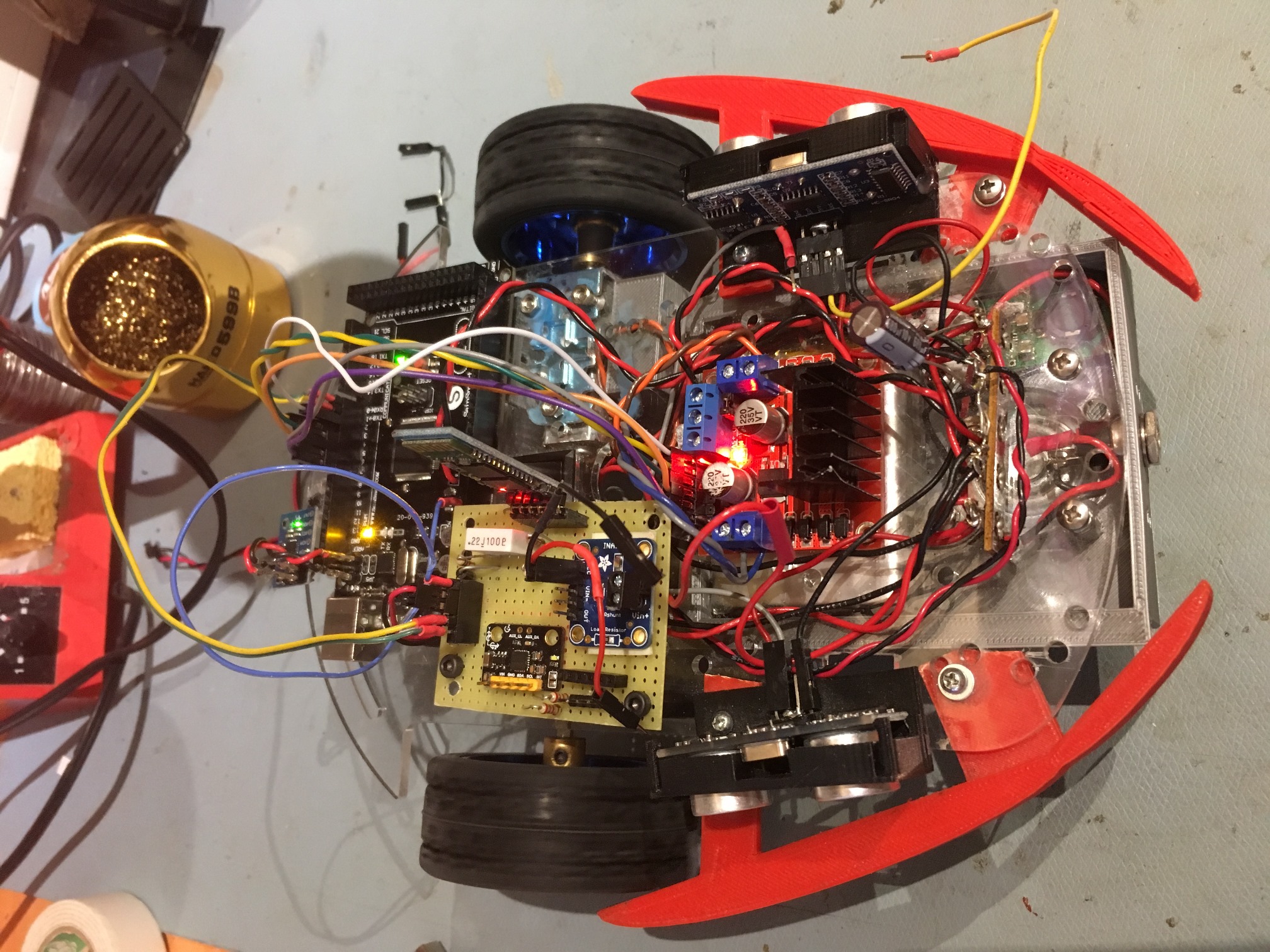
I have been attempting to use the Invensense MPU6050 6-axis IMU for some time now in both my two and four-wheel robots for improved wall-following ability. By measuring the relative heading change during turns, I could get the robot to accurately acquire and maintain a specified distance from the currently tracked wall. I say ‘attempting’, as I have experienced somewhat mixed results in getting reliable results from the IMU. A large part of the problem, as I described in this post, wasn’t the IMU at all, but rather the sensitivity of the Arduino I2C bus to RFI/EMI caused by the motor drivers. However, even after solving this problem, my programs would still occasionally ‘lose synch’ with the IMU’s FIFO buffer and start returning garbage for heading values – not good!
In addition to the I2C issue, there are several factors that make the MPU6050 harder do work with:
- Invensense, the company that makes the MPU6050 chip, appears to have been purchased by TDK, and their technical support forums don’t appear to be supported any longer.
- Apparently there are significant pieces of the MPU6050 firmware that aren’t freely available as human-readable code, so much of the MPU6050 magic is just that – magic. In particular, the details of how the MPU6050 handles its internal FIFO are (at least to me) completely unknown, except by reverse-engineering.
- While there is a lot of MPU6050-related information and code floating around out there in the i-verse, that is as much a trial as a blessing; it has been very difficult for me to wade through everything and to try to sort out the wheat from the chaff.
- Jeff Rowberg’s wonderful I2CDevLib contains support for the MPU6050, with examples. While it is fairly easy to get started using Jeff’s examples, it was difficult for me to understand how the examples work so I would know how to modify them for my application without running off into the bushes.
- Almost all the example code out there assumes an interrupt based IMU management scheme. For my wall-following robot application, the interrupt scheme was overkill and then some, so I wanted to use a polling arrangement, which is very poorly documented. Eventually I developed a working polling algorithm (described here) , which I now use in my robots.
- Invensense (now TDK) has released several updates to the MPU6050 firmware, and it is difficult (at least for me) to figure out what the differences are and whether or not those differences are worthwhile for my application. There is some information in the header files provided by Jeff Rowberg, but if there is any sort of formal change history, I haven’t found it.
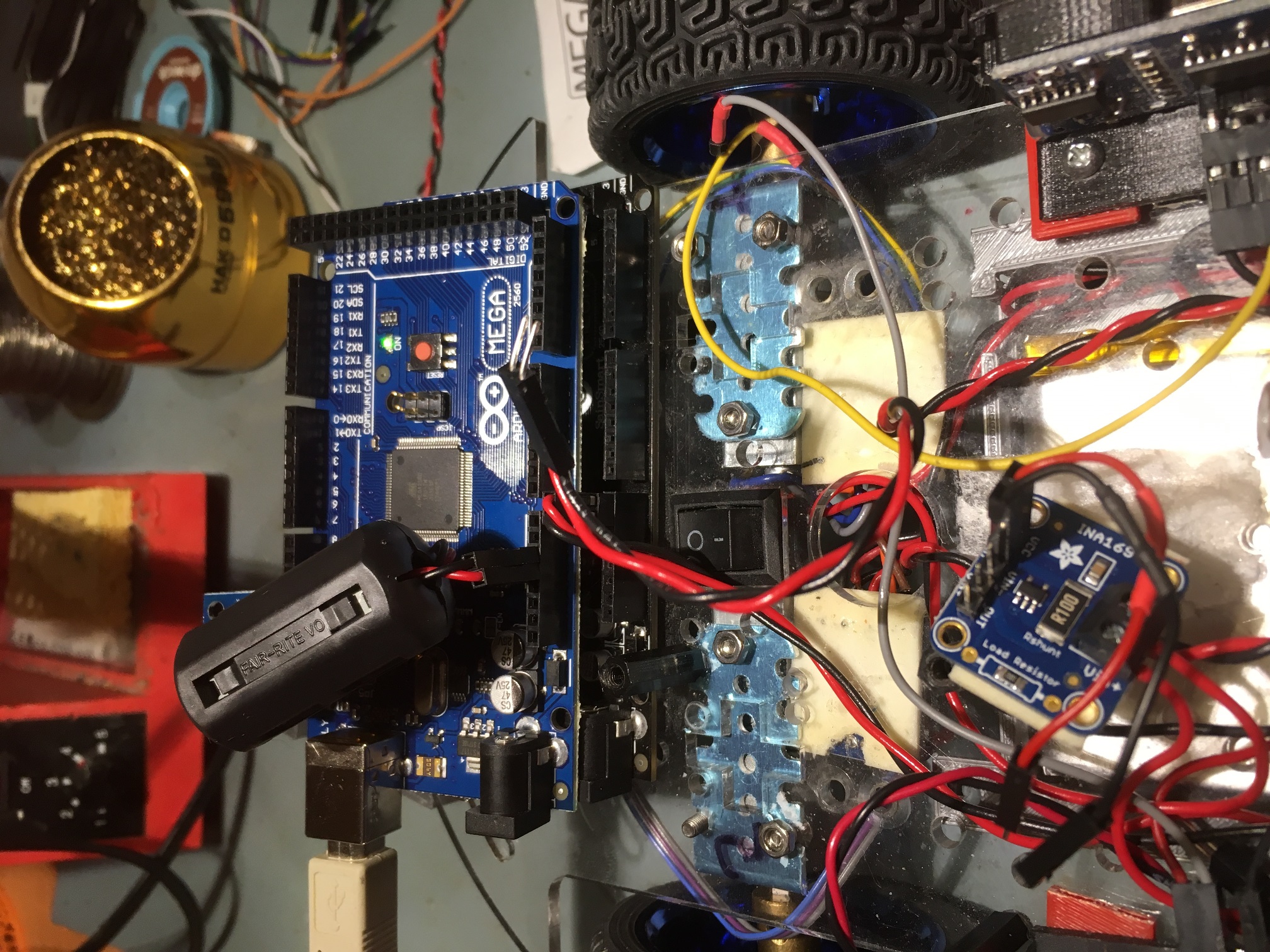
Despite all this, the MPU6050 is a wonderful device, and it’s EVERYWHERE – you can get MPU6050 modules from Adafruit, Sparkfun, DFRobots, and GY-521 Chinese knockoffs from eBay. The GY-521 modules have some reputed issues with quality control, but at about $1-2 per module, it’s hard to go wrong.
In my continued attempts to understand how the MPU6050 works, and the details of some of the latest example code provided on Jeff Rowberg’s Github site, I posted an issue related to a particular part of the example code that defied my ability to understand, as shown below:
|
1 2 3 4 5 6 7 8 9 10 |
// wait for MPU interrupt or extra packet(s) available while (!mpuInterrupt && fifoCount < packetSize) { if (mpuInterrupt && fifoCount < packetSize) { // try to get out of the infinite loop fifoCount = mpu.getFIFOCount(); } // other program behavior stuff here } |
This code obviously works, but I get a headache everytime I try to figure out how it makes sense. One of the replies I got from this post was from Homer Creutz, who I knew to be one of the very best experts on all things MPU6050. The gist of Homer’s reply was “yeah, it looks kinda clumsy, but it does work”. But then Homer went on to suggest an alternative using the modulus (%) operator that piqued my interest, as I had used this technique in my four-wheel robot code. In subsequent email conversations Homer went WAY out of his way to thoroughly answer my stupid questions about the MPU6050, especially about the issue with FIFO overflow. He sent me a link to this video explaining how circular buffers work, and the following graphic illustration (slightly edited for clarity) of the problem of MPU6050 overflow and multiple-byte packets
|
1 2 3 4 5 6 7 8 9 10 11 |
The problem is the buffer size doesn't evenly match the packet length so some fraction of the oldest packet gets partially overwritten with the newest packet shifting the first pointer into the middle of the oldest packet. so only a partial packet remains Buffer Size: 111112222233333444445555566666777 packet 7 overflows 2 bytes and wraps into packet 1 77 771112222233333444445555566666777 ^ So packet (1) only has a portion of its packet left and the pointer for the next read event points at the first #1 So if we read the (5 byte) packet we would get 11122 and the pointer would be at the third '2' of the next (2's) packet Continued reads would continue to retrieve part of one packet and part of the next, resulting in corrupted readings. |
The combination of the video and the above simple graphic finally allowed me to understand why properly managing FIFO overflow is so critical for successful MPU6050 implementations. Ironically, FIFO overflow management is more of an issue in my low-speed, high mass, low-dynamics environment than at the other end of the scale. In high-dynamics applications, FIFO overflow is almost never an issue because the application sucks data out of the FIFO as fast as it is put in, in order to provide the best possible stabilization and control. However, in low-dynamics applications like my wall-following robots, there is no need for IMU information more than a few times per second, meaning that the FIFO will almost certainly overflow if it isn’t proactively drained even if the information isn’t really needed.
Homer also sent me a couple of untested alternatives for FIFO management to replace the ‘while() within an if()’ algorithm, so I decided to test them and report the results back to Homer. After all, Homer was going WAY out of his way to answer my ignorant questions, so the least I could do was to be his lab tech. So, I started with Jeff Rowberg’s MPU6050_DMP6_using_DMP_V6.12 example (the one with the ‘while() within an if()’ snippet) and modified it to deliberately cause FIFO overflows. After a bit of debugging and some very slight changes to Homer’s code, I got the following output from a run using a 100 mSec delay at the start of loop():
|
1 2 3 4 5 6 7 8 9 10 11 12 13 14 15 16 17 18 19 20 21 22 23 24 25 26 27 28 29 30 31 32 33 34 35 36 37 38 39 40 41 42 43 44 45 46 47 48 |
Opening port Port open Initializing I2C devices... Testing device connections... MPU6050 connection successful Initializing DMP... >**......>...... // X Accel Y Accel Z Accel X Gyro Y Gyro Z Gyro //OFFSETS -3214, 2442, 866, 141, -22, 65 Enabling DMP... Enabling interrupt detection (Arduino external interrupt 0)... DMP ready! Waiting for first interrupt... Msec Yaw NumInt fifoCount 6342 -0.01 22 280 6446 -0.01 20 532 6548 0.00 20 812 FIFO overflow! 6752 0.02 41 252 6855 0.03 20 504 6958 0.03 20 784 FIFO overflow! 7161 0.06 41 252 7264 0.06 20 504 7367 0.06 20 784 FIFO overflow! 7571 0.08 41 252 7673 0.08 20 504 7777 0.08 20 784 FIFO overflow! 7981 0.11 41 252 8083 0.12 20 504 8186 0.12 20 784 FIFO overflow! 8390 0.14 41 252 8493 0.14 20 504 8596 0.14 20 784 FIFO overflow! 8800 0.17 41 252 8902 0.17 20 504 9006 0.17 20 784 FIFO overflow! 9209 0.20 41 252 9312 0.20 20 504 9415 0.20 20 784 FIFO overflow! Port closed |
As can be seen from the above, about 20 interrupt cycles are skipped in each loop() iteration, causing the 1024-byte FIFO contents to expand by either 280 or 252 bytes each time, until it overflowed and was reset. The example code handled FIFO overflows properly resetting the FIFO each time so that the retrieved yaw values continued to make sense.
The next step was to replace the example code with Homer’s proposed setup using the modulus operator for FIFO management. The first section below shows the example code loop() function before Homer’s modifications:
|
1 2 3 4 5 6 7 8 9 10 11 12 13 14 15 16 17 18 19 20 21 22 23 24 25 26 27 28 29 30 31 32 33 34 35 36 37 38 39 40 41 42 43 44 45 46 47 48 49 50 51 52 53 54 55 56 57 58 59 |
void loop() { delay(100); // if programming failed, don't try to do anything if (!dmpReady) return; // wait for MPU interrupt or extra packet(s) available while (!mpuInterrupt && fifoCount < packetSize) { if (mpuInterrupt && fifoCount < packetSize) { // try to get out of the infinite loop fifoCount = mpu.getFIFOCount(); } // other program behavior stuff here } // reset interrupt flag and get INT_STATUS byte mpuInterrupt = false; mpuIntStatus = mpu.getIntStatus(); // get current FIFO count fifoCount = mpu.getFIFOCount(); // check for overflow (this should never happen unless our code is too inefficient) if ((mpuIntStatus & _BV(MPU6050_INTERRUPT_FIFO_OFLOW_BIT)) || fifoCount >= 1024) { // reset so we can continue cleanly mpu.resetFIFO(); fifoCount = mpu.getFIFOCount(); Serial.println(F("FIFO overflow!")); // otherwise, check for DMP data ready interrupt (this should happen frequently) } else if (mpuIntStatus & _BV(MPU6050_INTERRUPT_DMP_INT_BIT)) { // wait for correct available data length, should be a VERY short wait while (fifoCount < packetSize) fifoCount = mpu.getFIFOCount(); // read a packet from FIFO mpu.getFIFOBytes(fifoBuffer, packetSize); // track FIFO count here in case there is > 1 packet available // (this lets us immediately read more without waiting for an interrupt) fifoCount -= packetSize; // display Euler angles in degrees mpu.dmpGetQuaternion(&q, fifoBuffer); mpu.dmpGetGravity(&gravity, &q); mpu.dmpGetYawPitchRoll(ypr, &q, &gravity); float yaw = ypr[0] * 180 / M_PI; mySerial.printf("%lu\t%3.2f\t%d\t%d\n", millis(), yaw, num_interrupts,fifoCount); num_interrupts = 0; //reset the interrupt counter (added for overflow testing) // blink LED to indicate activity blinkState = !blinkState; digitalWrite(LED_PIN, blinkState); } } |
And the following shows the same loop() function after implementing Homer’s suggested code:
|
1 2 3 4 5 6 7 8 9 10 11 12 13 14 15 16 17 18 19 20 21 22 23 24 25 26 27 28 29 30 31 32 33 34 35 36 37 38 39 40 41 42 43 44 45 46 47 48 49 50 51 52 53 54 55 56 57 58 59 60 61 62 63 64 65 66 67 68 69 70 71 72 73 74 75 76 77 78 79 80 81 82 83 84 85 86 87 88 89 90 91 92 93 94 95 96 97 98 99 100 101 102 103 104 105 106 107 108 109 110 111 112 113 114 115 116 117 118 119 120 121 122 123 124 125 |
// ================================================================ // === MAIN PROGRAM LOOP === // ================================================================ void loop() { delay(LOOP_DELAY_MSEC); // if programming failed, don't try to do anything if (!dmpReady) return; //// wait for MPU interrupt or extra packet(s) available //while (!mpuInterrupt && fifoCount < packetSize) //{ // if (mpuInterrupt && fifoCount < packetSize) // { // // try to get out of the infinite loop // fifoCount = mpu.getFIFOCount(); // } // // other program behavior stuff here //} // reset interrupt flag and get INT_STATUS byte mpuInterrupt = false; mpuIntStatus = mpu.getIntStatus(); //Homer Creutz's suggested FIFO handling code /* My thought process. And possibly a future update after testing. ### (Think of a world without overflow errors) How can this be true? **Always** the last byte in the buffer is **always** the last bye of a good packet. So shifting off the bytes from the beginning of the buffer until you only have a buffer with the correct number of bytes => cleaned! */ fifoCount = mpu.getFIFOCount(); if (fifoCount == 0) { return; // no data } if (fifoCount % packetSize != 0) // fifo_count will ALWAYS be a multiple of packetSize unless FIFO has overflowed! { mySerial.printf("fifo count %d off by %d, removing %d bytes\n", fifoCount, fifoCount % packetSize, (fifoCount % packetSize) + packetSize); // Remove the partial packet at the beginning of the overflowed buffer and just to be safe remove one // additional complete packet to make room in case a new packet is generated by the IMU while we are catching up. uint8_t fifoTrash[2 * PACKET_SIZE]; // Trash bin (bit bucket) - just a place to put the removed bytes. Can't be just PACKET_SIZE! mpu.getFIFOBytes(fifoTrash, (fifoCount % packetSize) + packetSize); fifoCount -= ((fifoCount % packetSize) + packetSize); //Correcting buffer content length without requesting over i2c saves clock ticks. //TEST fifoCount = mpu.getFIFOCount(); // lets see what we did if ((fifoCount % packetSize) == 0) { Serial.println("Success"); } if (fifoCount % packetSize != 0) { Serial.print("Failure\n we are still off by:"); Serial.println(fifoCount % packetSize); // The error should only be +- 1 but I think this should work Just corret the math above and get an extra byte from the buffer. } //END TEST } //if we get to here, we should be OK to retrieve & process one or more packets //retrieve all available packets, discarding all but the last one int initialFifoCount = fifoCount; //temp var for debug printout //while (fifoCount >= packetSize) //{ // mpu.getFIFOBytes(fifoBuffer, packetSize); // fifoCount -= packetSize; //} mpu.getFIFOBytes(fifoBuffer, packetSize); // display Euler angles in degrees mpu.dmpGetQuaternion(&q, fifoBuffer); mpu.dmpGetGravity(&gravity, &q); mpu.dmpGetYawPitchRoll(ypr, &q, &gravity); float yaw = ypr[0] * 180 / M_PI; mySerial.printf("%lu\t%3.2f\t%d\t%d\n", millis(), yaw, num_interrupts, initialFifoCount); // Now the buffer should be fixed so get the data //// get current FIFO count //fifoCount = mpu.getFIFOCount(); //// check for overflow (this should never happen unless our code is too inefficient) //if ((mpuIntStatus & _BV(MPU6050_INTERRUPT_FIFO_OFLOW_BIT)) || fifoCount >= 1024) { // // reset so we can continue cleanly // mpu.resetFIFO(); // fifoCount = mpu.getFIFOCount(); // Serial.println(F("FIFO overflow!")); // // otherwise, check for DMP data ready interrupt (this should happen frequently) //} //else if (mpuIntStatus & _BV(MPU6050_INTERRUPT_DMP_INT_BIT)) //{ // // wait for correct available data length, should be a VERY short wait // while (fifoCount < packetSize) fifoCount = mpu.getFIFOCount(); // // read a packet from FIFO // mpu.getFIFOBytes(fifoBuffer, packetSize); // // track FIFO count here in case there is > 1 packet available // // (this lets us immediately read more without waiting for an interrupt) // fifoCount -= packetSize; //// display Euler angles in degrees //mpu.dmpGetQuaternion(&q, fifoBuffer); //mpu.dmpGetGravity(&gravity, &q); //mpu.dmpGetYawPitchRoll(ypr, &q, &gravity); //float yaw = ypr[0] * 180 / M_PI; //mySerial.printf("%lu\t%3.2f\t%d\t%d\n", millis(), yaw, num_interrupts,fifoCount); num_interrupts = 0; //reset the interrupt counter (added for overflow testing) // blink LED to indicate activity blinkState = !blinkState; digitalWrite(LED_PIN, blinkState); //} } |
This resulted in the following output:
|
1 2 3 4 5 6 7 8 9 10 11 12 13 14 15 16 17 18 |
Enabling DMP... Enabling interrupt detection (Arduino external interrupt 0)... DMP ready! Waiting for first interrupt... FIFO packet size = 28 Loop Delay Duration = 100 Msec Yaw NumInt fifoCount 6352 -0.01 23 336 6455 -0.01 20 588 6558 -0.01 20 840 fifo count 1024 off by 16, removing 44 bytes Success 6664 0.00 21 980 fifo count 1024 off by 16, removing 44 bytes Success 6769 0.01 21 980 fifo count 1024 off by 16, removing 44 bytes Success |
Showing that FIFO overflow was indeed handled properly. The FIFO overflowed after the 3rd time through the loop, (the returned count was capped at the 1024-byte physical length of the FIFO), and Homer’s code correctly removed the 16 corrupted bytes at the beginning of the FIFO, plus one more 28-byte packet. The subsequent mpu.getFIFOBytes() call retrieved an entire valid packet, which was then process to produce a valid yaw value. Of course, since only one extra packet was removed, the FIFO overflowed again when the next 336 bytes were loaded during the 100 mSec delay at the start of the next loop() iteration.
When the code snippet to retrieve all available packets
|
1 2 3 4 5 |
while (fifoCount >= packetSize) { mpu.getFIFOBytes(fifoBuffer, packetSize); fifoCount -= packetSize; } |
was uncommented from the above program, I got an almost perfect output as shown below:
|
1 2 3 4 5 6 7 8 9 10 11 12 13 14 15 16 17 18 19 20 21 22 23 24 25 26 27 28 29 30 31 32 33 34 35 36 37 38 39 40 41 42 43 44 45 46 47 48 49 50 51 52 53 54 55 56 57 58 59 60 61 62 63 64 65 66 67 68 69 70 71 72 73 74 75 76 77 78 79 80 81 82 83 84 85 86 87 88 89 90 91 92 93 94 95 96 97 98 99 100 101 102 103 104 105 106 107 108 109 110 111 112 113 114 115 116 117 118 119 120 121 122 123 124 125 126 127 128 129 130 131 132 133 134 135 136 137 138 139 140 141 142 143 144 145 146 147 148 149 150 151 152 153 154 155 156 157 158 159 |
Enabling DMP... Enabling interrupt detection (Arduino external interrupt 0)... DMP ready! Waiting for first interrupt... FIFO packet size = 28 Loop Delay Duration = 100 Msec Yaw NumInt fifoCount 6548 -0.01 24 308 6658 0.00 22 308 6767 0.01 22 308 6878 0.08 22 308 6987 0.08 22 308 7098 0.08 22 308 7207 0.08 22 308 7317 -0.15 22 308 7427 -0.43 22 308 7537 -1.33 22 308 7647 -3.48 22 308 7757 -4.60 22 308 7867 -5.88 22 308 7976 -9.80 22 308 8087 -14.42 22 308 8197 -18.48 22 308 8306 -21.65 22 308 8417 -24.99 22 308 8526 -29.19 22 308 8637 -31.01 22 308 8747 -31.98 22 308 fifo count 328 off by 20, removing 48 bytes Failure we are still off by:8 8859 2.04 23 288 fifo count 288 off by 8, removing 36 bytes Success 8970 -35.75 22 252 9080 -41.23 22 308 9190 -45.99 22 308 9300 -49.48 22 308 9410 -51.00 22 308 9520 -49.38 22 308 9630 -44.49 22 308 9740 -42.31 22 308 9849 -40.04 22 308 9960 -36.22 22 308 10070 -31.17 22 308 10180 -26.80 22 308 10290 -21.15 22 308 10400 -15.81 22 308 10510 -10.01 22 308 10619 -4.34 22 308 10730 0.71 21 308 10840 5.08 21 308 10950 9.02 21 308 11060 12.83 21 308 11170 17.01 21 308 11280 20.36 21 308 11389 22.87 21 308 11500 23.38 21 308 11610 21.58 21 308 11720 16.90 22 308 11830 12.34 22 308 11940 7.13 22 308 12050 2.37 22 308 12160 -1.98 22 308 12270 -6.28 22 308 12380 -10.03 22 308 12490 -13.42 22 308 12600 -17.08 22 308 12710 -20.90 22 308 12820 -25.41 22 308 12931 -31.22 22 308 13040 -37.94 22 308 13150 -44.69 22 308 13260 -50.34 22 308 13370 -56.20 22 308 13480 -61.89 22 308 13590 -66.95 22 308 13701 -70.84 22 308 13810 -72.08 22 308 13920 -70.26 22 308 14030 -63.59 22 308 14140 -55.27 22 308 14251 -46.95 22 308 14360 -36.96 22 308 14471 -26.82 22 308 14580 -17.27 22 308 14691 -7.14 22 336 14801 0.27 21 308 14911 5.57 21 308 15021 9.76 21 308 15131 13.64 21 308 15241 17.11 21 308 15351 20.46 21 308 15461 21.17 22 308 15571 23.74 22 308 15681 24.44 22 308 15792 21.27 22 308 15901 14.62 22 308 16011 8.09 22 308 16121 3.13 22 308 16231 -2.51 22 308 16342 -7.89 22 308 16451 -13.60 22 308 16562 -20.02 22 308 16671 -25.73 22 308 16781 -30.85 22 308 16891 -35.78 22 308 17001 -40.88 22 308 17112 -45.68 22 308 17221 -50.89 22 308 17332 -55.38 22 308 17441 -60.69 22 308 17552 -61.97 22 308 17661 -57.13 22 308 17771 -49.59 22 308 17882 -41.19 22 308 17991 -31.43 22 308 18102 -22.63 22 308 18211 -15.25 22 308 18322 -7.35 22 308 18432 0.98 22 308 18541 8.27 22 308 18652 13.92 22 308 18761 18.61 21 308 18872 22.81 21 308 18981 26.26 21 308 19092 28.21 21 308 19202 28.76 21 308 19311 25.07 21 308 19422 22.43 21 308 19531 22.44 21 308 19642 22.44 22 308 19751 22.45 22 308 19862 22.45 22 308 19972 22.46 22 308 20082 22.47 22 308 20192 22.47 22 308 20302 22.48 22 308 20412 22.48 22 308 20521 22.48 22 308 20632 22.49 22 308 20742 22.50 22 308 20852 22.50 22 308 20962 22.50 22 308 21072 22.51 22 308 21182 22.52 22 308 21293 22.53 22 308 21402 22.53 22 308 21513 22.54 22 308 21622 22.55 22 308 21732 22.55 22 308 21842 22.56 22 308 21952 22.56 22 308 22063 22.57 22 308 22172 22.58 22 308 22283 22.58 22 336 22393 22.59 21 308 Port closed |
There were 4 bad values starting at 15250 mSec, as shown below
|
1 2 3 4 5 6 7 8 9 10 11 12 |
Msec Yaw NumInt fifoCount 8637 -31.01 22 308 8747 -31.98 22 308 fifo count 328 off by 20, removing 48 bytes Failure we are still off by:8 8859 2.04 23 288 fifo count 288 off by 8, removing 36 bytes Success 8970 -35.75 22 252 9080 -41.23 22 308 9190 -45.99 22 308 |
I’m not real sure what happened here. A FIFO count of 308 is nowhere near the overflow condition, and it is an even multiple of 28 (the packet size), so everything should have gone swimmingly. However the displayed value of 2.04 degrees at time 8859 mSec is clearly incorrect, as I was manually (and slowly) rotating the MPU at the time.
Another issue with all of this is the FIFO count associated with the number of interrupts shown in the output. 22 interrupts should produce 22*28 = 616 bytes, but mpu.GetFIFOCount() only returns 308 – exactly half the expected value. So, either the packet size is actually 14 bytes (not very likely, as mpu.GetPacketSize() returns 28) or the IMU is only loading half a packet on each interrupt. I added digitalWrite() statements to the ISR so I could directly monitor interrupt occurrences with my O’scope, and the interrupts happened exactly as expected, at approximately 4.58 mSec intervals (about 220Hz). The 100 mSec delay at the top of loop() should produce approximately 100/4.58 = ~22 interrupts each iteration, and that is what is reported in the output. So, why the x2 error in the reported FIFO count?
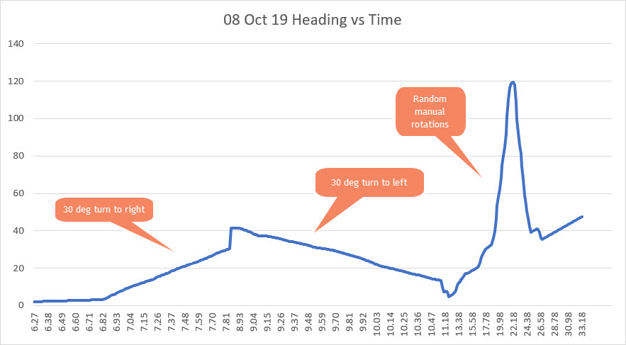
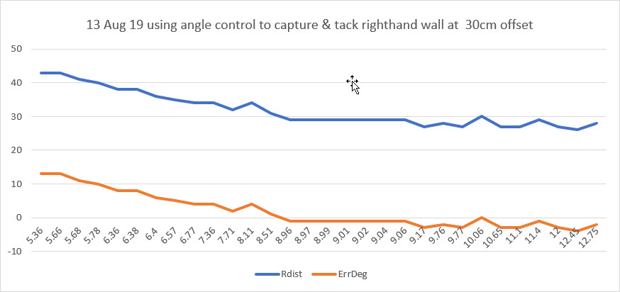
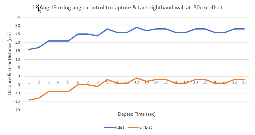
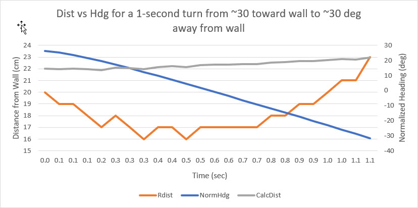
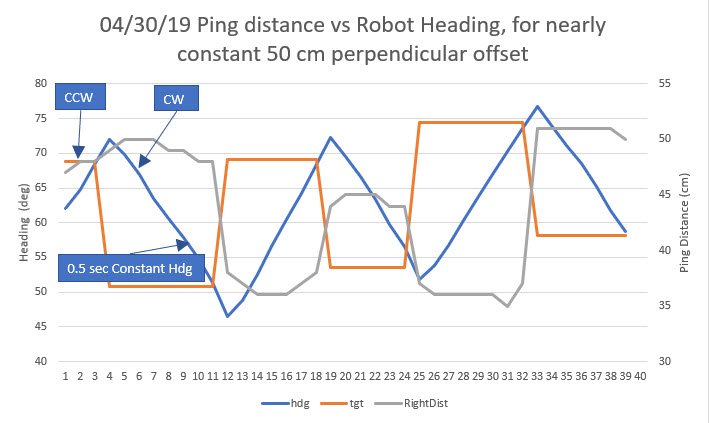
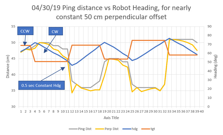
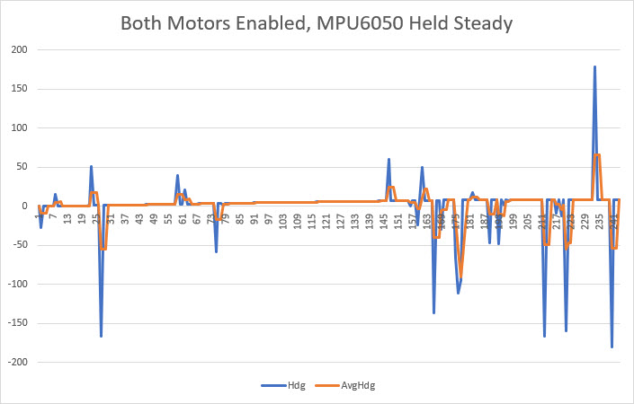
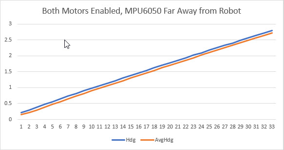
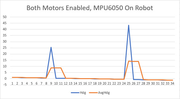
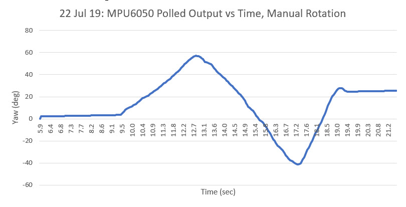
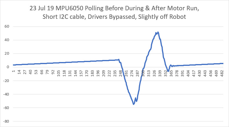
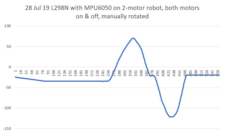
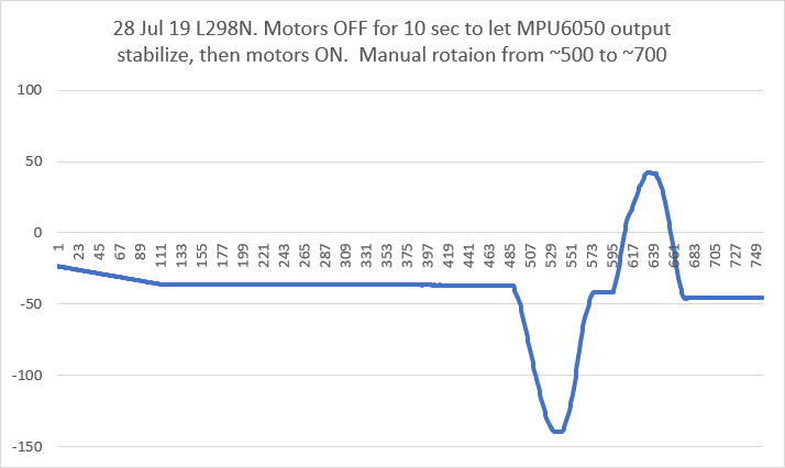
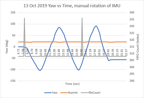
I ran another test, and this one responded perfectly for as long as I let it run (about 22 seconds). During the run I manually rotated the robot (and its attached IMU) back and forth, as shown in the following Excel plot
14 October 2019 Update:
There is clearly something not-quite-right with the way the MPU6050 reports the current length of the FIFO contents. Here are the results from a recent run:
|
1 2 3 4 5 6 7 8 9 |
23136 -54.28 22 308 23246 -58.35 22 308 fifo count 320 off by 12, removing 40 bytes Success 23358 173.66 23 320 fifo count 324 off by 16, removing 44 bytes Success 23470 -68.37 22 324 23579 -72.26 22 308 |
Aside from the fact that 22 x 28 = 616 not the reported 308, there is also the problem that after one more interrupt (23 vs 22), the reported FIFO content length didn’t go up by 14 (half the expected 28, but…) but instead by 12 bytes – what the heck? This clearly implies that MPU interrupts aren’t entirely synchronous with actually filling the FIFO – like some sort of race condition? In other words, the number that is reported by mpu.getFIFOCount() isn’t always an integer multiple of the packet size! This is contrary to Homer’s assumption that the only way for mpu.getFIFOCount() to retrieve a non-integral multiple was for the FIFO to overflow. This clearly is not happening here, but I’m still getting non-integer multiple results. Here’s another snippet from the same run:
|
1 2 3 4 5 6 7 8 9 10 11 12 |
66611 18.47 22 308 66720 10.44 22 308 66830 1.27 22 308 66940 -8.23 22 308 fifo count 316 off by 8, removing 36 bytes Success 67052 -179.17 22 316 fifo count 328 off by 20, removing 48 bytes Success 67164 -30.46 22 328 67273 -41.32 22 308 67384 -50.26 22 308 |
In the above snippet, it can be seen that a 22 interrupt interval can sometimes result in 316 bytes being reported rather than the expected (ignoring for the moment the issue of a 2x error), and the ‘success’ of removing 36 bytes still resulted in a ‘bad’ yaw value computation (-179.17) 308. In the very next loop iteration, 22 interrupts resulted in 328 bytes being reported. This time removing the excess allowed a valid yaw computation (-30.46). So, a 22 interrupt loop interval can result in 308 (the ‘normal’ result), 316, or 328.
15 October 2019 Update:
I changed the loop() delay time from 100 mSec to 200 mSec, and (with no other changes) re-ran the test, with the following output:
|
1 2 3 4 5 6 7 8 9 10 11 12 13 14 15 16 17 18 19 20 21 22 23 24 25 26 27 28 29 30 31 32 33 34 35 36 37 38 39 40 41 42 43 44 45 46 47 48 49 50 51 52 53 54 55 56 57 58 59 60 61 62 63 64 65 66 67 68 69 70 71 72 73 74 75 76 77 78 79 80 81 82 83 84 85 86 87 88 89 90 91 92 93 94 95 96 97 98 99 100 101 102 103 104 105 106 107 108 109 110 111 112 113 114 115 116 117 118 119 120 121 122 123 124 125 126 127 128 129 130 131 132 133 134 135 136 137 138 139 140 141 142 143 144 145 146 147 148 149 150 151 152 153 154 155 156 157 158 159 160 161 |
Initializing DMP... >**......>...... // X Accel Y Accel Z Accel X Gyro Y Gyro Z Gyro //OFFSETS -3170, 2462, 866, 141, -21, 65 Enabling DMP... Enabling interrupt detection (Arduino external interrupt 0)... DMP ready! Waiting for first interrupt... FIFO packet size = 28 Loop Delay Duration = 200 Msec Yaw NumInt fifoCount 6478 0.01 45 616 6695 0.02 44 588 6914 0.04 43 616 7131 0.05 44 616 7349 0.06 43 616 7566 0.08 44 616 7783 0.10 43 588 8000 0.11 44 616 8218 0.13 43 616 8435 0.14 43 616 8652 0.15 43 588 8870 0.24 43 616 9088 -3.59 43 616 9305 -19.19 43 616 9522 -28.68 43 588 9740 -37.90 43 616 9957 -48.50 44 616 10175 -58.37 43 616 10392 -66.84 44 616 10609 -63.76 43 588 10827 -48.45 44 616 11044 -29.68 43 616 11262 -8.64 43 616 11480 7.26 43 588 11697 19.23 43 616 11915 30.05 44 616 12132 42.07 43 616 12349 54.01 44 588 12567 63.80 43 616 12784 70.89 44 616 13002 62.04 43 616 13220 46.38 43 616 13437 36.15 43 588 13655 24.08 43 616 13873 8.87 43 616 14090 -7.64 43 616 14307 -17.03 43 588 14525 -27.11 43 616 14742 -42.61 44 616 14960 -57.30 43 616 15177 -68.07 44 616 15394 -68.52 43 588 15612 -51.36 44 616 15830 -31.03 43 616 16048 -9.46 43 616 16265 11.58 43 588 16482 29.96 43 616 16700 47.85 44 616 16918 63.22 43 616 17135 71.19 44 616 17352 63.74 43 588 17570 61.40 44 616 17787 61.42 43 616 18006 61.43 43 616 18223 61.46 43 588 18440 61.47 43 616 18658 61.49 44 616 18875 61.51 43 616 fifo count 600 off by 12, removing 40 bytes Success 19094 -179.20 44 600 fifo count 604 off by 16, removing 44 bytes Success 19312 61.54 44 604 19530 61.55 43 616 19748 61.57 43 616 19965 61.58 43 616 20184 61.60 43 616 20401 61.61 43 588 20618 61.64 43 616 20836 61.65 44 616 21053 61.67 43 616 21271 61.68 44 616 21488 61.70 43 588 21705 61.71 44 616 21923 61.73 43 616 22141 61.74 43 616 22358 61.75 43 588 22576 61.77 43 616 22794 61.79 44 616 23011 61.80 43 616 23229 61.82 44 616 23446 61.83 43 588 23663 61.85 44 616 23881 61.87 43 616 24098 61.89 43 616 24315 61.90 43 588 24534 61.92 43 616 24751 61.94 44 616 24969 61.95 43 616 25186 61.97 44 588 25403 61.98 43 616 25621 62.00 44 616 25839 59.93 43 616 26056 59.96 43 616 26273 59.97 43 588 26491 59.98 43 616 26708 60.01 44 616 26927 60.02 43 616 27144 60.04 44 588 27361 60.05 43 616 27579 60.07 44 616 27796 60.16 43 616 28014 60.14 43 616 28231 59.07 43 588 28448 48.92 43 616 28666 39.44 43 616 28884 20.26 43 616 29102 0.51 44 588 29319 -18.84 43 616 29537 -32.57 44 616 29754 -45.71 43 616 29972 -58.43 44 616 30189 -68.70 43 588 30406 -77.72 43 616 30624 -83.67 43 616 30841 -84.50 43 616 31058 -75.26 43 588 31277 -57.56 43 616 31494 -45.87 44 616 31712 -45.94 43 616 31930 -45.08 44 616 32146 -30.33 43 588 32364 -8.66 44 616 32582 12.01 43 616 32799 29.13 43 616 33016 42.07 43 588 33234 51.87 43 616 33452 55.97 44 616 33670 49.55 43 616 33887 33.85 44 588 34104 14.59 43 616 34322 -2.01 44 616 34539 -9.69 43 616 34757 -9.62 43 616 34974 -9.60 43 588 35191 -9.58 43 616 35409 -9.56 43 616 35627 -9.54 43 616 35844 -9.52 43 588 36062 -9.50 43 616 36279 -9.48 44 616 36497 -9.47 43 616 36714 -9.46 44 616 36931 -9.44 43 588 37149 -9.43 44 616 37366 -9.41 43 616 37584 -9.39 43 616 37801 -9.38 43 588 |
The above results showed the expected 42-43 interrupt count between loop() iterations, and the expected (ignoring for the moment the 2x error factor) FIFO contents byte count of 588-616. However, there were a couple of anomalous occurrences on two consecutive loop() iterations at 19094 and 19312 mSec. The first one reported a FIFO contents count of 600 instead of 616 and (even after error correction) a clearly erroneous yaw value of -179.20, and the second one reported 604 bytes and (after error correction) an apparently valid yaw value of 61.54.
After an email exchange with Homer, I tried replacing this line
|
1 |
fifoCount -= ((fifoCount % packetSize) + packetSize); //Correcting buffer content length without requesting over i2c saves clock ticks. |
with this one:
|
1 |
fifoCount = mpu.getFIFOCount(); |
In the following section of Homer’s algorithm
|
1 2 3 4 5 6 7 8 9 10 11 12 13 14 15 16 17 18 19 20 21 22 23 24 25 26 27 28 29 30 31 32 33 34 35 36 37 38 39 40 41 42 43 44 |
//Homer Creutz's suggested FIFO handling code /* My thought process. And possibly a future update after testing. ### (Think of a world without overflow errors) How can this be true? **Always** the last byte in the buffer is **always** the last bye of a good packet. So shifting off the bytes from the beginning of the buffer until you only have a buffer with the correct number of bytes => cleaned! */ fifoCount = mpu.getFIFOCount(); int initialFifoCount = fifoCount; //temp var for debug printout if (fifoCount == 0) { return; // no data } if (fifoCount % packetSize != 0) // fifo_count will ALWAYS be a multiple of packetSize unless FIFO has overflowed! { //mySerial.printf("fifo count %d off by %d, removing %d bytes\n", fifoCount, fifoCount % packetSize, (fifoCount % packetSize) + packetSize); mySerial.printf("fifo count %d off by %d, removing %d bytes\n", fifoCount, fifoCount % packetSize, (fifoCount % packetSize) + packetSize); // Remove the partial packet at the beginning of the overflowed buffer and just to be safe remove one // additional complete packet to make room in case a new packet is generated by the IMU while we are catching up. uint8_t fifoTrash[2 * PACKET_SIZE]; // Trash bin (bit bucket) - just a place to put the removed bytes. Can't be just PACKET_SIZE! mpu.getFIFOBytes(fifoTrash, (fifoCount % packetSize) + packetSize); //fifoCount -= ((fifoCount % packetSize) + packetSize); //Correcting buffer content length without requesting over i2c saves clock ticks. fifoCount = mpu.getFIFOCount(); //TEST //fifoCount = mpu.getFIFOCount(); // lets see what we did if ((fifoCount % packetSize) == 0) { Serial.println("Success"); } if (fifoCount % packetSize != 0) { Serial.print("Failure\n we are still off by:"); Serial.println(fifoCount % packetSize); // The error should only be +- 1 but I think this should work Just corret the math above and get an extra byte from the buffer. } //END TEST } |
After this change, I re-ran the test at the 100 mSec loop() iteration delay setting with and without the above code change. In both cases, I still got errors trapped, as shown below (The test conditions for each run below are noted at the top of the text file)
|
1 2 3 4 5 6 7 8 9 10 11 12 13 14 15 16 17 18 19 20 21 22 23 24 25 26 27 28 29 30 31 32 33 34 35 36 37 38 39 40 41 42 43 44 45 46 47 48 49 50 51 52 53 54 55 56 57 58 59 60 61 62 63 64 65 66 67 68 69 70 71 72 73 74 75 76 77 78 79 80 81 82 83 84 85 86 87 88 89 90 91 92 93 94 95 96 97 98 99 100 101 102 103 104 105 106 107 108 109 110 111 112 113 114 115 116 117 118 119 120 121 122 123 124 125 126 127 128 129 130 131 132 133 134 135 136 137 138 139 |
fifoCount -= ((fifoCount % packetSize) + packetSize); //Correcting buffer content length without requesting over i2c saves clock ticks. //fifoCount = mpu.getFIFOCount(); Opening port Port open Initializing I2C devices... Testing device connections... MPU6050 connection successful Initializing DMP... >**......>...... // X Accel Y Accel Z Accel X Gyro Y Gyro Z Gyro //OFFSETS -3186, 2468, 876, 141, -27, 67 Enabling DMP... Enabling interrupt detection (Arduino external interrupt 0)... DMP ready! Waiting for first interrupt... FIFO packet size = 28 Loop Delay Duration = 100 Msec Yaw NumInt fifoCount 6434 0.00 24 336 6545 0.01 21 308 6654 0.01 21 308 6764 0.02 21 308 6875 0.03 21 308 6984 0.04 21 308 7095 0.04 21 308 7204 0.04 21 308 7314 0.05 21 308 7425 0.06 21 308 7534 0.07 21 308 7644 0.08 21 308 7754 0.08 21 308 7864 0.09 22 308 7973 0.10 22 308 8084 0.10 22 308 8194 0.11 22 308 8304 0.12 22 308 8414 0.13 22 308 8523 0.13 22 308 8634 0.14 22 308 8743 0.15 22 308 8853 0.15 22 308 8964 0.16 22 308 9073 0.17 22 308 9183 0.17 22 308 9293 0.19 22 308 9403 0.19 22 308 9512 0.20 22 308 9623 0.21 22 308 9733 0.22 22 308 9842 0.22 22 308 9953 0.22 22 308 10062 0.23 22 308 10172 0.24 22 308 10283 0.24 22 308 10392 0.25 22 308 10503 0.26 22 308 10612 0.27 22 308 10722 0.27 22 308 10832 0.28 22 308 10942 0.29 22 308 11053 0.29 22 308 11162 0.30 22 308 11272 0.31 22 308 11382 0.31 22 308 11492 0.32 22 308 11602 0.33 22 308 11712 0.34 22 308 11822 0.34 22 308 11932 0.35 22 308 12042 0.36 22 308 12152 0.36 22 308 12262 0.37 22 308 12371 0.38 22 308 12482 0.38 22 308 12592 0.38 22 308 12702 0.39 22 308 12812 0.40 22 308 12921 0.41 22 308 13032 0.41 22 308 13142 0.42 22 308 13252 0.43 22 308 13362 0.43 22 308 13471 0.44 22 308 13582 0.45 22 308 13691 0.46 22 308 13802 0.47 22 308 13912 0.48 21 308 14021 0.48 21 308 14132 0.49 21 308 14241 0.50 21 308 14352 0.51 21 308 14461 0.52 21 308 14571 0.52 21 308 14682 0.53 21 308 14791 0.53 21 308 14902 0.54 21 308 15011 0.55 22 308 15121 0.56 22 308 15232 0.56 22 308 15341 0.57 22 308 15452 0.57 22 308 15561 0.58 22 308 15672 0.59 22 308 15781 0.59 22 308 15891 0.60 22 308 16002 0.61 22 308 16111 0.62 22 308 16222 0.62 22 308 16331 0.63 22 308 16441 0.64 22 308 16551 0.64 22 308 16661 0.65 22 308 16772 0.66 22 308 16881 0.66 22 308 16991 0.67 22 308 17101 0.68 22 308 17211 0.69 22 308 17321 0.69 22 308 17431 0.70 22 308 17542 0.71 22 308 17651 0.71 22 308 17761 0.72 22 308 17871 0.73 22 308 17981 0.73 22 308 18092 0.73 22 308 18201 0.74 22 308 18311 0.75 22 308 18421 0.76 22 308 18531 0.76 22 308 18641 0.77 22 308 fifo count 324 off by 16, removing 44 bytes Success 18753 -0.55 23 324 fifo count 320 off by 12, removing 40 bytes Success 18865 0.78 22 320 18974 0.79 22 308 |
|
1 2 3 4 5 6 7 8 9 10 11 12 13 14 15 16 17 18 19 20 21 22 23 24 25 26 27 28 29 30 31 32 33 34 35 36 37 38 39 40 41 42 43 44 45 46 47 48 49 50 51 52 53 54 55 56 57 58 59 60 61 62 63 64 65 66 67 68 69 70 71 72 73 74 75 76 77 78 79 80 81 82 83 84 85 86 87 88 89 90 91 92 93 94 95 96 97 98 99 100 101 102 103 104 105 106 107 108 109 110 111 112 113 114 115 116 117 118 119 120 121 122 123 124 125 126 127 128 129 130 131 132 133 134 135 136 137 138 139 140 141 142 143 144 145 146 147 148 149 150 151 152 153 154 155 156 157 158 159 160 161 162 163 164 165 166 167 168 169 170 171 172 173 174 175 176 177 178 179 180 181 182 183 184 185 186 187 188 189 190 191 192 193 194 195 196 197 198 199 200 201 202 203 204 205 206 207 208 209 210 211 212 213 214 215 216 217 218 219 220 221 222 223 224 225 226 227 228 229 230 231 232 233 234 235 236 237 238 239 240 241 242 243 244 245 246 247 248 249 250 251 252 253 254 255 256 257 258 259 260 261 262 263 264 265 266 267 268 269 270 271 272 273 274 275 276 277 278 279 280 281 282 283 284 285 286 287 288 289 290 291 292 293 294 295 296 297 298 299 300 301 302 303 304 305 306 307 308 309 310 311 312 313 314 315 316 317 318 319 320 321 322 323 324 325 326 327 328 329 330 331 332 333 334 335 336 337 338 339 340 341 342 343 344 345 346 347 348 349 350 351 352 353 354 355 356 357 358 359 360 361 362 363 364 365 366 367 368 369 370 371 372 373 374 375 376 377 378 379 380 381 382 383 384 385 386 387 388 389 390 391 392 393 394 395 396 397 398 399 400 401 402 403 404 405 406 407 408 409 410 411 412 413 414 415 416 417 418 419 420 421 422 423 424 425 426 427 428 429 430 431 432 433 434 435 436 437 438 439 440 441 442 443 444 445 446 447 448 449 450 451 452 453 454 455 456 457 458 459 460 461 462 463 464 465 466 467 468 469 470 471 472 473 474 475 476 477 478 479 480 481 482 483 484 485 486 487 488 489 490 491 492 493 494 495 496 497 498 499 500 501 502 503 504 505 506 507 508 509 510 511 512 513 514 515 516 517 518 519 520 521 522 523 524 525 526 527 528 529 530 531 532 533 534 535 536 537 538 539 540 541 542 543 544 545 546 547 548 549 550 551 552 553 554 555 556 557 558 559 560 561 562 563 564 565 566 567 568 569 570 571 572 573 574 575 576 577 578 579 580 581 582 583 584 585 586 587 588 589 590 591 592 593 594 595 596 597 598 |
//fifoCount -= ((fifoCount % packetSize) + packetSize); //Correcting buffer content length without requesting over i2c saves clock ticks. fifoCount = mpu.getFIFOCount(); Opening port Port open Initializing I2C devices... Testing device connections... MPU6050 connection successful Initializing DMP... >**......>...... // X Accel Y Accel Z Accel X Gyro Y Gyro Z Gyro //OFFSETS -3182, 2466, 870, 139, -25, 66 Enabling DMP... Enabling interrupt detection (Arduino external interrupt 0)... DMP ready! Waiting for first interrupt... FIFO packet size = 28 Loop Delay Duration = 100 Msec Yaw NumInt fifoCount 6368 0.00 24 308 6478 0.01 22 308 6588 0.02 22 308 6697 0.03 22 308 6808 0.04 22 308 6918 0.04 22 308 7027 0.06 22 308 7138 0.06 22 308 7247 0.08 22 308 7357 0.08 22 308 7468 0.09 22 308 7577 0.10 22 308 7687 0.11 22 308 7797 0.12 22 308 7907 0.13 22 308 8016 0.14 22 308 8127 0.15 22 308 8237 0.15 22 308 8347 0.16 22 308 8457 0.17 22 308 8566 0.18 22 308 8677 0.19 22 308 8786 0.20 22 308 8896 0.21 22 308 fifo count 312 off by 4, removing 32 bytes Failure we are still off by:24 9009 -180.00 23 312 9118 0.23 22 308 9229 0.24 22 308 9338 0.24 22 308 9448 0.25 22 308 9559 0.26 22 308 9668 0.27 22 308 9778 0.28 22 308 9887 0.29 22 308 9998 0.29 22 308 10107 0.31 22 308 10217 0.31 22 308 10328 0.33 22 308 10437 0.34 22 308 10547 0.34 22 308 10657 0.36 22 308 10767 0.36 22 308 10876 0.37 22 308 10987 0.38 22 308 11097 0.39 22 308 11207 0.40 22 308 11317 0.41 22 308 11426 0.41 22 308 11537 0.43 22 308 11646 0.43 22 308 11757 0.43 22 308 11867 0.45 22 308 11976 0.45 22 308 12087 0.46 22 308 12196 0.48 22 308 12307 0.48 22 308 12417 0.49 22 308 12526 0.50 22 308 12637 0.51 22 308 12746 0.52 22 308 12857 0.52 22 308 12966 0.53 22 308 13076 0.55 22 308 13187 0.55 22 308 13296 0.56 22 308 13407 0.57 22 308 13516 0.58 22 308 13626 0.59 22 308 13736 0.60 22 308 13846 0.61 22 308 13957 0.62 22 308 14066 0.62 22 308 14176 0.64 22 308 14286 0.64 21 308 14396 0.65 21 308 14507 0.66 21 308 14616 0.67 21 308 14726 0.68 21 308 14836 0.69 21 308 14946 0.70 21 308 15056 0.71 21 308 15166 0.71 21 308 15276 0.73 21 308 15386 0.73 22 308 15496 0.74 22 308 15606 0.76 22 308 15716 0.76 22 308 15825 0.77 22 308 15936 0.78 22 308 16046 0.79 22 308 16156 0.80 22 308 16266 0.80 22 308 16375 0.81 22 308 16486 0.82 22 308 16595 0.83 22 308 16706 0.83 22 308 16816 0.84 22 308 16925 0.85 22 308 17036 0.86 22 308 17145 0.87 22 308 17256 0.88 22 308 17366 0.90 22 308 17475 0.90 22 308 17586 0.91 22 308 17695 0.92 22 308 17806 0.92 22 308 17915 0.94 22 308 18025 0.94 22 308 18136 0.95 22 308 18245 0.97 22 308 18356 0.97 22 308 18465 0.98 22 308 18575 0.99 22 308 18685 1.00 22 308 18795 1.01 22 308 18906 1.01 22 308 19015 1.03 22 308 19125 1.04 22 308 19235 1.04 22 308 19345 1.06 22 308 19456 1.06 22 308 19565 1.07 22 308 19676 1.08 22 336 19785 1.08 21 308 19896 1.09 21 308 20005 1.11 21 308 20116 1.11 21 308 20226 1.12 21 308 20336 1.12 21 308 20446 1.12 21 308 20555 1.13 22 308 20666 1.13 22 308 20775 1.13 22 308 20886 1.13 22 308 20996 1.13 22 308 21105 1.13 22 308 21216 1.13 22 308 21325 1.14 22 308 21436 1.14 22 308 21545 1.15 22 308 21655 1.15 22 308 21766 1.15 22 308 21875 1.15 22 308 21986 1.15 22 308 22095 1.15 22 308 22205 1.15 22 308 22316 1.15 22 308 22425 1.15 22 308 22536 1.15 22 308 22645 1.15 22 308 22755 1.15 22 308 22865 1.15 22 308 22975 1.15 22 308 23086 1.16 22 308 23195 1.16 22 308 23305 1.17 22 308 23415 1.17 22 308 23525 1.17 22 308 23635 1.17 22 308 23745 1.17 22 308 23855 1.17 22 308 23965 1.18 22 308 24075 1.18 22 308 24185 1.18 22 308 24295 1.18 22 308 24404 1.18 22 308 24515 1.18 22 308 24625 1.19 22 308 24734 1.19 22 308 24845 1.19 22 308 24954 1.20 22 308 25065 1.20 22 308 25175 1.20 22 308 25284 1.20 21 308 25395 1.20 21 308 25504 1.20 21 308 25615 1.20 21 308 25724 1.20 21 308 25834 1.20 21 308 25945 1.20 21 308 26054 1.20 21 308 26165 1.20 21 308 26274 1.20 21 308 26384 1.20 21 308 26494 1.20 22 308 26604 1.20 22 308 26715 1.21 22 308 26824 1.21 22 308 26934 1.21 22 308 27044 1.21 22 308 27154 1.21 22 308 27265 1.22 22 308 27374 1.22 22 308 27485 1.22 22 308 27594 1.22 22 308 27704 1.22 22 308 27814 1.22 22 308 27924 1.22 22 308 28034 1.22 22 308 28144 1.22 22 308 28254 1.22 22 308 28364 1.22 22 308 28474 1.22 22 308 28583 1.22 22 308 28694 1.22 22 308 28804 1.22 22 308 28914 1.22 22 308 29024 1.22 22 308 29134 1.22 22 308 29244 1.22 22 308 29353 1.22 22 308 29464 1.21 22 308 29574 1.21 22 308 29684 1.21 22 308 29794 1.21 22 308 29903 1.21 22 308 30014 1.21 22 308 30124 1.22 22 308 30234 1.22 22 308 30344 1.22 22 308 30453 1.21 22 308 30565 1.21 22 336 30674 1.22 21 308 30784 1.21 21 308 30895 1.21 21 308 31004 1.21 21 308 31115 1.21 21 308 31224 1.21 21 308 31334 1.21 22 308 31444 1.21 22 308 31554 1.21 22 308 31665 1.21 22 308 31774 1.21 22 308 31884 1.21 22 308 31994 1.21 22 308 32104 1.21 22 308 32215 1.21 22 308 32324 1.21 22 308 32435 1.21 22 308 32544 1.22 22 308 32654 1.22 22 308 32764 1.22 22 308 32874 1.22 22 308 32985 1.22 22 308 33094 1.22 22 308 33204 1.22 22 308 33314 1.22 22 308 33424 1.22 22 308 33534 1.22 22 308 33644 1.22 22 308 33754 1.22 22 308 33864 1.22 22 308 33974 1.22 22 308 34084 1.22 22 308 34194 1.22 22 308 34304 1.22 22 308 34414 1.22 22 308 34524 1.22 22 308 34634 1.22 22 308 34744 1.22 22 308 34854 1.22 22 308 34964 1.22 22 308 35074 1.22 22 308 35184 1.22 22 308 35294 1.22 22 308 35404 1.22 22 308 35514 1.22 21 308 35623 1.22 21 308 35734 1.22 21 308 35844 1.22 21 308 35954 1.22 21 308 36064 1.22 21 308 36173 1.22 21 308 36284 1.22 21 308 36393 1.22 21 308 36504 1.22 21 308 36614 1.22 22 308 36724 1.22 22 308 36834 1.22 22 308 36943 1.21 22 308 37054 1.21 22 308 37164 1.21 22 308 37274 1.21 22 308 37384 1.21 22 308 37493 1.21 22 308 37604 1.21 22 308 37713 1.21 22 308 37824 1.21 22 308 37934 1.20 22 308 38044 1.20 22 308 38154 1.20 22 308 38263 1.20 22 308 38374 1.20 22 308 38483 1.20 22 308 38594 1.20 22 308 38704 1.20 22 308 38813 1.20 22 308 38924 1.20 22 308 39033 1.20 22 308 39144 1.20 22 308 39254 1.20 22 308 39363 1.20 22 308 39474 1.20 22 308 39583 1.20 22 308 39694 1.20 22 308 39803 1.20 22 308 39913 1.20 22 308 40024 1.20 22 308 40133 1.20 22 308 40244 1.20 22 308 40354 1.19 22 336 40464 1.19 21 308 40574 1.19 21 308 40684 1.19 21 308 40794 1.19 21 308 40904 1.19 21 308 41014 1.18 21 308 41124 1.18 22 308 41234 1.18 22 308 41344 1.18 22 308 41454 1.18 22 308 41564 1.18 22 308 41674 1.18 22 308 41784 1.18 22 308 41894 1.18 22 308 42004 1.18 22 308 42114 1.18 22 308 42224 1.18 22 308 42334 1.18 22 308 42444 1.17 22 308 42554 1.17 22 308 42663 1.17 22 308 42774 1.17 22 308 42884 1.17 22 308 42994 1.17 22 308 43104 1.17 22 308 43213 1.16 22 308 43324 1.17 22 308 43433 1.17 22 308 43544 1.16 22 308 43654 1.16 22 308 43763 1.16 22 308 43874 1.16 22 308 43983 1.16 22 308 44094 1.15 22 308 44204 1.15 22 308 44314 1.15 22 308 44424 1.15 22 308 44533 1.15 22 308 44644 1.16 22 308 44753 1.15 22 308 44864 1.15 22 308 44974 1.15 22 308 45084 1.15 22 308 45194 1.15 22 308 45303 1.15 21 308 45414 1.15 21 308 45523 1.15 21 308 45634 1.15 21 308 45744 1.15 21 308 45853 1.15 21 308 45964 1.15 21 308 46073 1.15 21 308 46184 1.15 21 308 46294 1.15 22 308 46404 1.15 22 308 46514 1.15 22 308 46623 1.14 22 308 46734 1.14 22 308 46843 1.14 22 308 46954 1.14 22 308 47064 1.14 22 308 47173 1.14 22 308 47284 1.13 22 308 47393 1.13 22 308 47504 1.13 22 308 47613 1.13 22 308 47724 1.13 22 308 47834 1.13 22 308 47943 1.13 22 308 48054 1.13 22 308 48163 1.13 22 308 48274 1.13 22 308 48384 1.13 22 308 48493 1.13 22 308 48604 1.13 22 308 48713 1.13 22 308 48824 1.13 22 308 48933 1.13 22 308 49043 1.13 22 308 49154 1.13 22 308 49263 1.13 22 308 49374 1.13 22 308 49483 1.13 22 308 49594 1.12 22 308 49703 1.12 22 308 49813 1.12 22 308 49924 1.12 22 336 50034 1.12 21 308 50144 1.11 21 308 50254 1.11 21 308 50364 1.11 21 308 50475 1.11 21 308 50584 1.11 21 308 50694 1.11 22 308 50804 1.11 22 308 50914 1.11 22 308 51024 1.11 22 308 51134 1.11 22 308 51245 1.11 22 308 51354 1.11 22 308 51464 1.11 22 308 51574 1.11 22 308 51684 1.11 22 308 51794 1.11 22 308 51904 1.11 22 308 52014 1.11 22 308 52124 1.11 22 308 52234 1.11 22 308 52344 1.11 22 308 52454 1.11 22 308 52564 1.11 22 308 52674 1.11 22 308 52784 1.11 22 308 52894 1.11 22 308 53004 1.11 22 308 53114 1.11 22 308 53224 1.11 22 308 53334 1.10 22 308 53444 1.10 22 308 53554 1.10 22 308 53664 1.10 22 308 53774 1.10 22 308 53883 1.10 22 308 53994 1.10 22 308 54104 1.10 22 308 54214 1.10 22 308 54324 1.10 22 308 54434 1.09 22 308 54544 1.09 22 308 54653 1.09 21 308 54764 1.09 21 308 54874 1.10 21 308 54984 1.10 21 308 55094 1.09 21 308 55203 1.10 21 308 55314 1.10 21 308 55424 1.10 21 308 55534 1.10 21 308 55644 1.10 22 308 55754 1.10 22 308 55864 1.10 22 308 55973 1.10 22 308 56084 1.10 22 308 56194 1.10 22 308 56304 1.10 22 308 56414 1.10 22 308 56523 1.10 22 308 56634 1.09 22 308 56743 1.09 22 308 56854 1.09 22 308 56964 1.09 22 308 57073 1.09 22 308 57184 1.09 22 308 57293 1.09 22 308 57404 1.09 22 308 57513 1.09 22 308 57624 1.09 22 308 57734 1.10 22 308 57843 1.09 22 308 57954 1.09 22 308 58063 1.09 22 308 58174 1.09 22 308 58284 1.09 22 308 58393 1.08 22 308 58504 1.08 22 308 58613 1.08 22 308 58724 1.08 22 308 58833 1.08 22 308 58943 1.08 22 308 59054 1.08 22 308 59163 1.08 22 308 59274 1.08 22 308 59383 1.08 22 308 59494 1.08 22 336 59604 1.08 21 308 59714 1.08 21 308 59824 1.08 21 308 59934 1.08 21 308 60044 1.08 21 308 60154 1.08 21 308 60264 1.08 22 308 60374 1.08 22 308 60484 1.08 22 308 60594 1.08 22 308 60704 1.07 22 308 60814 1.07 22 308 60924 1.07 22 308 61034 1.07 22 308 61144 1.07 22 308 61254 1.08 22 308 61364 1.08 22 308 61474 1.08 22 308 61584 1.08 22 308 61693 1.08 22 308 61804 1.07 22 308 61914 1.08 22 308 62024 1.07 22 308 62134 1.07 22 308 62244 1.08 22 308 62354 1.08 22 308 62464 1.07 22 308 62574 1.07 22 308 62684 1.07 22 308 62794 1.07 22 308 62904 1.07 22 308 63013 1.07 22 308 63124 1.07 22 308 63234 1.07 22 308 63344 1.07 22 308 63454 1.07 22 308 63564 1.07 22 308 63674 1.07 22 308 63783 1.07 22 308 63894 1.07 22 308 64004 1.07 22 308 64114 1.07 22 308 64224 1.07 21 308 64333 1.07 21 308 64444 1.07 21 308 64553 1.07 21 308 64664 1.07 21 308 64774 1.07 21 308 64884 1.07 21 308 64994 1.07 21 308 65103 1.07 21 308 65214 1.07 21 308 65324 1.07 21 308 65434 1.07 22 308 65544 1.07 22 308 65653 1.07 22 308 65764 1.07 22 308 65873 1.06 22 308 65984 1.06 22 308 66094 1.06 22 308 66203 1.06 22 308 66314 1.06 22 308 66423 1.06 22 308 66534 1.06 22 308 66643 1.06 22 308 66754 1.07 22 308 66864 1.07 22 308 66973 1.07 22 308 67084 1.06 22 308 67193 1.06 22 308 67304 1.06 22 308 67414 1.06 22 308 67523 1.06 22 308 67634 1.06 22 308 67743 1.06 22 308 67854 1.06 22 308 67963 1.06 22 308 68074 1.06 22 308 68184 1.06 22 308 68293 1.06 22 308 68404 1.06 22 308 68513 1.06 22 308 68624 1.06 22 308 68733 1.06 22 308 fifo count 320 off by 12, removing 40 bytes Failure we are still off by:16 68846 179.48 23 320 fifo count 296 off by 16, removing 44 bytes Success 68958 1.06 22 296 |
So then, also at Homer’s suggestion, I instrumented the code to get the FIFO count rapidly several times after an error detection to see if the first mpu.getFIFOCount() occurred while data was actually being loaded into the FIFO and therefore got an erroneous count. So, I changed Homer’s code correction section to the following:
|
1 2 3 4 5 6 7 8 9 10 11 12 13 14 15 16 17 18 19 20 21 22 23 24 25 26 27 28 29 30 31 32 33 34 35 36 37 38 39 40 41 42 43 44 45 46 47 48 49 50 51 52 53 54 55 56 57 |
//Homer Creutz's suggested FIFO handling code /* My thought process. And possibly a future update after testing. ### (Think of a world without overflow errors) How can this be true? **Always** the last byte in the buffer is **always** the last bye of a good packet. So shifting off the bytes from the beginning of the buffer until you only have a buffer with the correct number of bytes => cleaned! */ fifoCount = mpu.getFIFOCount(); int initialFifoCount = fifoCount; //temp var for debug printout if (fifoCount == 0) { return; // no data } if (fifoCount % packetSize != 0) // fifo_count will ALWAYS be a multiple of packetSize unless FIFO has overflowed! { //10/15/19 gfp - experiment to see if the FIFO count grows over time mySerial.printf("fifo count %d off by %d\n", fifoCount, fifoCount % packetSize); //mySerial.printf("fifo count %d off by %d, removing %d bytes\n", fifoCount, fifoCount % packetSize, (fifoCount % packetSize) + packetSize); for (size_t i = 0; i < 3; i++) { fifoCount = mpu.getFIFOCount(); mySerial.printf("fifo count %d \n", fifoCount); } } ////10/15/19 gfp - experiment: now try again if (fifoCount % packetSize != 0) // fifo_count will ALWAYS be a multiple of packetSize unless FIFO has overflowed! { mySerial.printf("fifo count %d off by %d, removing %d bytes\n", fifoCount, fifoCount % packetSize, (fifoCount % packetSize) + packetSize); // Remove the partial packet at the beginning of the overflowed buffer and just to be safe remove one // additional complete packet to make room in case a new packet is generated by the IMU while we are catching up. uint8_t fifoTrash[2 * PACKET_SIZE]; // Trash bin (bit bucket) - just a place to put the removed bytes. Can't be just PACKET_SIZE! mpu.getFIFOBytes(fifoTrash, (fifoCount % packetSize) + packetSize); //fifoCount -= ((fifoCount % packetSize) + packetSize); //Correcting buffer content length without requesting over i2c saves clock ticks. fifoCount = mpu.getFIFOCount(); //TEST //fifoCount = mpu.getFIFOCount(); // lets see what we did if ((fifoCount % packetSize) == 0) { Serial.println("Success"); } if (fifoCount % packetSize != 0) { Serial.print("Failure\n we are still off by:"); Serial.println(fifoCount % packetSize); // The error should only be +- 1 but I think this should work Just corret the math above and get an extra byte from the buffer. } //END TEST } |
and re-ran the 100 mSec loop() iteration delay test. What I got was this:
|
1 2 3 4 5 6 7 8 9 10 |
57091 0.69 22 308 57200 0.69 22 308 57311 0.69 22 308 fifo count 334 off by 26 fifo count 336 fifo count 336 fifo count 336 57423 0.69 23 334 57534 0.69 22 308 57644 0.69 22 308 |
Wow! the FIFO count changed! The first mpu.getFIFOCount() at the top of the detection section got 334, and the next 3 calls all got 336! So the first mpu.getFIFOCount() call must have hit the mpu 26/28 of the way through the packet load!
So, the MPU6050 packet load scheme isn’t atomic and there is, in fact, some sort of a race condition. I think we have all been assuming that the MPU6050 loads the FIFO with a complete packet and then triggers an interrupt, while it appears that it is actually happening the other way around; the interrupt is triggered and then the packet is loaded into the FIFO. Most of the time this doesn’t cause a problem, but if you ‘get lucky’, the register associated with the mpu.getFIFOCount() call is read before the entire packet is loaded
16 October 2019 Update:
Homer asked me to change the code to determine exactly how long it takes to “clear the error”, which I take to mean “how long would a program have to wait for the MPU6050 to finish loading the rest of the packet into the FIFO”. Homer sent me some sample code, which I modified slightly to produce the output Homer was looking for, as shown below:
|
1 2 3 4 5 6 7 8 9 10 11 12 13 14 15 16 17 18 19 20 21 22 23 24 25 26 27 28 29 30 31 32 33 34 35 36 37 38 39 40 41 42 |
void loop() { delay(LOOP_DELAY_MSEC); // if programming failed, don't try to do anything if (!dmpReady) return; // reset interrupt flag and get INT_STATUS byte mpuInterrupt = false; mpuIntStatus = mpu.getIntStatus(); //Homer Creutz's suggested FIFO handling code unsigned long ErrorStart; unsigned long ErrorEnd; int Flag = 0; fifoCount = mpu.getFIFOCount(); int errorcount = fifoCount; ErrorStart = micros(); while (fifoCount % packetSize && fifoCount < MAX_FIFO_BYTES) { fifoCount = mpu.getFIFOCount(); ErrorEnd = micros(); Flag = 1; } if (Flag) { mySerial.printf("Error with fifo count = %d. It took %lu microseconds to clear the error\n", errorcount,(ErrorEnd-ErrorStart)); } if (fifoCount == MAX_FIFO_BYTES) { mpu.resetFIFO(); } mySerial.printf("%lu\t%d\t%d\n", millis(), num_interrupts,mpu.getFIFOCount()); num_interrupts = 0; //reset the interrupt counter (added for overflow testing) // blink LED to indicate activity blinkState = !blinkState; digitalWrite(LED_PIN, blinkState); } |
When I ran this code, I got the following output:
|
1 2 3 4 5 6 7 8 9 10 11 12 13 14 15 16 17 18 19 20 21 22 23 24 25 26 27 28 29 30 31 32 33 34 35 36 37 38 39 40 41 |
Opening port Port open Initializing I2C devices... Testing device connections... MPU6050 connection successful Initializing DMP... >**......>...... // X Accel Y Accel Z Accel X Gyro Y Gyro Z Gyro //OFFSETS -3180, 2472, 868, 140, -25, 66 Enabling DMP... Enabling interrupt detection (Arduino external interrupt 0)... DMP ready! Waiting for first interrupt... FIFO packet size = 28 Loop Delay Duration = 100 Msec Yaw NumInt fifoCount 6411 23 308 6512 20 588 6614 20 868 6714 20 0 6815 21 308 6917 20 588 7017 20 868 7118 20 0 ... ... ... 16421 20 0 16523 20 280 16624 20 560 Error with fifo count = 863. It took 172 microseconds to clear the error 16727 21 868 16828 20 0 16928 20 280 17030 21 560 17131 20 840 17232 20 0 ... ... ... |
21 October 2019 Update:
After several more email exchanges with Homer, he believes that he has now come up with pretty ‘bullet-proof’ way of handling MPU6050 errors, with the following subroutine
|
1 2 3 4 5 6 7 8 9 10 11 12 13 14 15 16 17 18 19 20 21 22 23 24 25 26 27 28 29 30 31 32 33 34 35 36 37 38 39 40 41 42 43 44 45 46 47 48 49 50 51 |
// ================================================================ // === OVERFLOW DETECTION ROUTINE === // ================================================================ // Returns 1) when nothing special was done // 2) when recovering from overflow // 0) when no valid data is available // ================================================================ uint8_t GetCurrentFIFOPacket(uint8_t *data, uint8_t length)// overflow proof { uint8_t Error; int8_t more; uint8_t Flag = 0; uint8_t overflowed = 0; do { if (Error = (fifoCount = mpu.getFIFOCount()) % length) { if (Error = (fifoCount = mpu.getFIFOCount()) % length) { mpuIntStatus = mpu.getIntStatus(); if (mpuIntStatus & _BV(MPU6050_INTERRUPT_FIFO_OFLOW_BIT)) { mpu.getFIFOBytes(fifoBuffer, Error); // lets remove the overflow portion mpu.getFIFOBytes(fifoBuffer, length); overflowed = 1; if (Error = (fifoCount = mpu.getFIFOCount()) % length) // there could be some remaining bytes to deal with that snuck in after we freed up some space { mpu.getFIFOBytes(fifoBuffer, Error); // lets remove the overflow portion again if ((fifoCount = mpu.getFIFOCount()) % length) { mpu.resetFIFO(); Serial.println("Failed to recover overflow error"); return 0; } } } } } fifoCount = mpu.getFIFOCount(); if (fifoCount >= packetSize) { mpu.getFIFOBytes(fifoBuffer, length); Flag = 1 + overflowed; fifoCount -= packetSize; } } while (fifoCount >= packetSize); return Flag; } |
The idea behind this subroutine is to ensure that any overflow condition is detected and managed properly. The routine is completely independent of interrupts, so it can be used in a program using interrupts or polling.
Homer also sent me some test results using the program, with a variable loop delay time designed to be just below and then just above the delay required to overflow the buffer. This demonstrated that his subroutine properly handles FIFO overflow conditions, and returns valid packet data whenever possible.
|
1 2 3 4 5 6 7 8 9 10 11 12 13 14 15 16 17 18 19 20 21 22 23 24 25 26 27 28 29 30 31 32 33 34 35 36 37 38 39 40 41 42 43 44 45 46 47 48 49 50 51 52 53 54 55 56 57 58 59 60 61 62 63 64 65 |
178 Flag = 2 Status = 2ypr -2.48 -0.16 -0.07 179 Flag = 1 Status = 1ypr -2.48 -0.16 -0.07 175 Flag = 1 Status = 1ypr -2.48 -0.14 -0.07 176 Flag = 1 Status = 1ypr -2.49 -0.15 -0.06 177 Flag = 1 Status = 1ypr -2.49 -0.14 -0.07 178 Flag = 2 Status = 2ypr -2.50 -0.14 -0.07 179 Flag = 2 Status = 2ypr -2.50 -0.14 -0.07 175 Flag = 1 Status = 1ypr -2.50 -0.14 -0.07 176 Flag = 1 Status = 1ypr -2.50 -0.14 -0.07 177 Flag = 1 Status = 1ypr -2.50 -0.14 -0.07 178 Flag = 1 Status = 1ypr -2.50 -0.13 -0.06 179 Flag = 2 Status = 2ypr -2.50 -0.14 -0.07 175 Flag = 1 Status = 1ypr -2.50 -0.13 -0.07 176 Flag = 1 Status = 1ypr -2.50 -0.13 -0.07 177 Flag = 1 Status = 1ypr -2.50 -0.13 -0.07 178 Flag = 1 Status = 1ypr -2.50 -0.13 -0.07 179 Flag = 2 Status = 2ypr -2.50 -0.13 -0.07 175 Flag = 1 Status = 1ypr -2.50 -0.13 -0.07 176 Flag = 2 Status = 2ypr -2.50 -0.13 -0.06 177 Flag = 2 Status = 2ypr -2.50 -0.13 -0.07 178 Flag = 1 Status = 1ypr -2.50 -0.13 -0.08 179 Flag = 1 Status = 1ypr -2.49 -0.13 -0.07 175 Flag = 1 Status = 1ypr -2.50 -0.13 -0.08 176 Flag = 1 Status = 1ypr -2.48 -0.13 -0.08 177 Flag = 2 Status = 2ypr -2.49 -0.13 -0.08 178 Flag = 2 Status = 2ypr -2.48 -0.13 -0.08 179 Flag = 1 Status = 1ypr -2.48 -0.13 -0.08 175 Flag = 1 Status = 1ypr -2.48 -0.13 -0.08 176 Flag = 1 Status = 1ypr -2.48 -0.13 -0.08 177 Flag = 1 Status = 1ypr -2.48 -0.13 -0.07 178 Flag = 2 Status = 2ypr -2.48 -0.13 -0.07 179 Flag = 1 Status = 1ypr -2.48 -0.14 -0.07 175 Flag = 1 Status = 1ypr -2.48 -0.14 -0.07 176 Flag = 1 Status = 1ypr -2.48 -0.13 -0.07 177 Flag = 1 Status = 1ypr -2.48 -0.13 -0.07 178 Flag = 2 Status = 2ypr -2.47 -0.13 -0.07 179 Flag = 2 Status = 2ypr -2.48 -0.14 -0.07 175 Flag = 1 Status = 1ypr -2.48 -0.14 -0.07 176 Flag = 1 Status = 1ypr -2.48 -0.13 -0.07 177 Flag = 1 Status = 1ypr -2.48 -0.14 -0.06 178 Flag = 1 Status = 1ypr -2.48 -0.14 -0.06 179 Flag = 2 Status = 2ypr -2.48 -0.14 -0.07 175 Flag = 1 Status = 1ypr -2.47 -0.15 -0.06 176 Flag = 1 Status = 1ypr -2.47 -0.15 -0.07 177 Flag = 1 Status = 1ypr -2.47 -0.15 -0.06 178 Flag = 1 Status = 1ypr -2.47 -0.15 -0.06 179 Flag = 2 Status = 2ypr -2.48 -0.16 -0.06 175 Flag = 1 Status = 1ypr -2.47 -0.16 -0.06 176 Flag = 2 Status = 2ypr -2.47 -0.16 -0.06 177 Flag = 2 Status = 2ypr -2.47 -0.16 -0.06 178 Flag = 1 Status = 1ypr -2.47 -0.16 -0.06 179 Flag = 1 Status = 1ypr -2.47 -0.16 -0.06 175 Flag = 1 Status = 1ypr -2.47 -0.15 -0.06 176 Flag = 1 Status = 1ypr -2.47 -0.15 -0.06 177 Flag = 2 Status = 2ypr -2.47 -0.14 -0.05 178 Flag = 2 Status = 2ypr -2.48 -0.13 -0.07 179 Flag = 1 Status = 1ypr -2.48 -0.13 -0.07 175 Flag = 1 Status = 1ypr -2.48 -0.13 -0.07 176 Flag = 1 Status = 1ypr -2.48 -0.13 -0.07 177 Flag = 1 Status = 1ypr -2.48 -0.13 -0.07 178 Flag = 2 Status = 2ypr -2.48 -0.13 -0.07 179 Flag = 1 Status = 1ypr -2.48 -0.13 -0.07 175 Flag = 1 Status = 1ypr -2.48 -0.13 -0.07 176 Flag = 1 Status = 1ypr -2.49 -0.13 -0.07 177 Flag = 1 Status = 1ypr -2.49 -0.13 -0.06 |
In the above output, the first column is the loop delay in mSec, then the ‘Flag’ value returned by the subroutine, and then the ypr (yaw,pitch, roll) values extracted from the buffer filled by the subroutine. As is shown, loop delay values above about 177 mSec start returning ‘2’ Flag values, indicating the routine detected (and recovered from) an overflow condition.
I replicated this experiment on my end, but discovered that for my installation, I had to use a loop delay almost exactly twice the value used by Homer (360-370 vs 177-178). The implication is that either my MPU6050 is loading the FIFO at one-half the rate of Homer’s unit, or my IMU has a buffer size twice the one being used by Homer. Curioser and Curioser ;-).
Here’s my code and results:
|
1 2 3 4 5 6 7 8 9 10 11 12 13 14 15 16 17 18 19 20 21 22 23 24 25 26 27 28 29 30 31 32 33 34 35 36 37 38 39 40 41 42 43 44 45 46 47 48 49 50 51 52 53 54 55 56 57 58 59 60 61 62 63 64 65 66 67 68 69 70 71 72 73 74 75 76 77 78 79 80 81 82 83 84 85 86 87 88 89 90 91 92 93 94 95 96 97 98 99 100 101 102 103 104 105 106 107 108 109 110 111 112 113 114 115 116 117 118 119 120 121 122 123 124 125 126 127 128 129 130 131 132 133 134 135 136 137 138 139 140 141 142 143 144 145 146 147 148 149 150 151 152 153 154 155 156 157 158 159 160 161 162 163 164 165 166 167 168 169 170 171 172 173 174 175 176 177 178 179 180 181 182 183 184 185 186 187 188 189 190 191 192 193 194 195 196 197 198 199 200 201 202 203 204 205 206 207 208 209 210 211 212 213 214 215 216 217 218 219 220 221 222 223 224 225 226 227 228 229 230 231 232 233 234 235 236 237 238 239 240 241 242 243 244 245 246 247 248 249 250 251 252 253 254 255 256 257 258 259 260 |
/* Name: Arduino_MPU6050_Overflow2.ino Created: 10/20/2019 7:59:21 PM Author: FRANKWIN10\Frank */ /* 10/04/19 gfp: modified to remove everything not needed for my environment */ // I2Cdev and MPU6050 must be installed as libraries, or else the .cpp/.h files // for both classes must be in the include path of your project #include "I2Cdev.h" #include <PrintEx.h> #include "MPU6050_6Axis_MotionApps_V6_12.h" //#include "MPU6050.h" // not necessary if using MotionApps include file // class default I2C address is 0x68 // specific I2C addresses may be passed as a parameter here // AD0 low = 0x68 (default for SparkFun breakout and InvenSense evaluation board) // AD0 high = 0x69 MPU6050 mpu; //MPU6050 mpu(0x69); // <-- use for AD0 high PrintEx mySerial(Serial); #define OUTPUT_READABLE_YAWPITCHROLL #define INTERRUPT_PIN 2 // use pin 2 on Arduino Uno & most boards #define LED_PIN 13 // (Arduino is 13, Teensy is 11, Teensy++ is 6) bool blinkState = false; // MPU control/status vars bool dmpReady = false; // set true if DMP init was successful uint8_t mpuIntStatus; // holds actual interrupt status byte from MPU uint8_t devStatus; // return status after each device operation (0 = success, !0 = error) uint16_t packetSize; // expected DMP packet size (default is 42 bytes) uint16_t fifoCount; // count of all bytes currently in FIFO uint8_t fifoBuffer[64]; // FIFO storage buffer // orientation/motion vars Quaternion q; // [w, x, y, z] quaternion container VectorInt16 aa; // [x, y, z] accel sensor measurements VectorInt16 gy; // [x, y, z] gyro sensor measurements VectorInt16 aaReal; // [x, y, z] gravity-free accel sensor measurements VectorInt16 aaWorld; // [x, y, z] world-frame accel sensor measurements VectorFloat gravity; // [x, y, z] gravity vector float euler[3]; // [psi, theta, phi] Euler angle container float ypr[3]; // [yaw, pitch, roll] yaw/pitch/roll container and gravity vector //10/13/18 gfp: added to support Homer Creutz's algorithm testing const int PACKET_SIZE = 28; //const int LOOP_DELAY_MSEC = 100; const int LOOP_DELAY_MSEC = 360; const int INT_MONITOR_PIN = 50; const int MAX_FIFO_BYTES = 1024; const int MAX_LINE_LENGTH = 80; //added 10/20/19 long int startMsec = 0; //added 10/20/19 // ================================================================ // === INTERRUPT DETECTION ROUTINE === // ================================================================ volatile bool mpuInterrupt = false; // indicates whether MPU interrupt pin has gone high volatile int num_interrupts = 0; void dmpDataReady() { mpuInterrupt = true; num_interrupts++; //added for overflow testing digitalWrite(INT_MONITOR_PIN, HIGH); digitalWrite(INT_MONITOR_PIN, LOW); } // ================================================================ // === INITIAL SETUP === // ================================================================ void setup() { // initialize serial communication Serial.begin(115200); while (!Serial); // wait for Leonardo enumeration, others continue immediately // initialize device Serial.println(F("Initializing I2C devices...")); mpu.initialize(); pinMode(INTERRUPT_PIN, INPUT); // verify connection Serial.println(F("Testing device connections...")); Serial.println(mpu.testConnection() ? F("MPU6050 connection successful") : F("MPU6050 connection failed")); //// wait for ready //Serial.println(F("\nSend any character to begin DMP programming and demo: ")); //while (Serial.available() && Serial.read()); // empty buffer //while (!Serial.available()); // wait for data //while (Serial.available() && Serial.read()); // empty buffer again // load and configure the DMP Serial.println(F("Initializing DMP...")); devStatus = mpu.dmpInitialize(); // supply your own gyro offsets here, scaled for min sensitivity mpu.setXGyroOffset(51); mpu.setYGyroOffset(8); mpu.setZGyroOffset(21); mpu.setXAccelOffset(1150); mpu.setYAccelOffset(-50); mpu.setZAccelOffset(1060); // make sure it worked (returns 0 if so) if (devStatus == 0) { // Calibration Time: generate offsets and calibrate our MPU6050 mpu.CalibrateAccel(6); mpu.CalibrateGyro(6); Serial.println(); mpu.PrintActiveOffsets(); // turn on the DMP, now that it's ready Serial.println(F("Enabling DMP...")); mpu.setDMPEnabled(true); // enable Arduino interrupt detection Serial.print(F("Enabling interrupt detection (Arduino external interrupt ")); Serial.print(digitalPinToInterrupt(INTERRUPT_PIN)); Serial.println(F(")...")); attachInterrupt(digitalPinToInterrupt(INTERRUPT_PIN), dmpDataReady, RISING); mpuIntStatus = mpu.getIntStatus(); // set our DMP Ready flag so the main loop() function knows it's okay to use it Serial.println(F("DMP ready! Waiting for first interrupt...")); dmpReady = true; // get expected DMP packet size for later comparison packetSize = mpu.dmpGetFIFOPacketSize(); mySerial.printf("FIFO packet size = %d\n", packetSize); mySerial.printf("Loop Delay Duration = %d\n", LOOP_DELAY_MSEC); } else { // ERROR! // 1 = initial memory load failed // 2 = DMP configuration updates failed // (if it's going to break, usually the code will be 1) Serial.print(F("DMP Initialization failed (code ")); Serial.print(devStatus); Serial.println(F(")")); } // configure pins for output pinMode(LED_PIN, OUTPUT); pinMode(INT_MONITOR_PIN, OUTPUT); //mySerial.printf("\nMsec\tCnt\tX\tY\n"); mySerial.printf("\nMsec\tYaw\tFlag\n"); startMsec = millis(); } // ================================================================ // === MAIN PROGRAM LOOP === // ================================================================ void loop() { // if programming failed, don't try to do anything if (!dmpReady) return; for (size_t i = 0; i < 10; i++) { int myDelay = LOOP_DELAY_MSEC + i; for (size_t i = 0; i < 10; i++) { delay(myDelay); int Flag = GetCurrentFIFOPacket(fifoBuffer, packetSize); float yawval = getYawVal(fifoBuffer); mySerial.printf("%d\t%lu\t%3.2f\t%d\n", myDelay, millis(), yawval, Flag); } } } // ================================================================ // === OVERFLOW DETECTION ROUTINE === // ================================================================ // Returns 1) when nothing special was done // 2) when recovering from overflow // 0) when no valid data is available // ================================================================ uint8_t GetCurrentFIFOPacket(uint8_t *data, uint8_t length)// overflow proof { uint8_t Error; int8_t more; uint8_t Flag = 0; uint8_t overflowed = 0; do { if (Error = (fifoCount = mpu.getFIFOCount()) % length) { if (Error = (fifoCount = mpu.getFIFOCount()) % length) { mpuIntStatus = mpu.getIntStatus(); if (mpuIntStatus & _BV(MPU6050_INTERRUPT_FIFO_OFLOW_BIT)) { mpu.getFIFOBytes(data, Error); // lets remove the overflow portion mpu.getFIFOBytes(data, length); overflowed = 1; if (Error = (fifoCount = mpu.getFIFOCount()) % length) // there could be some remaining bytes to deal with that snuck in after we freed up some space { mpu.getFIFOBytes(data, Error); // lets remove the overflow portion again if ((fifoCount = mpu.getFIFOCount()) % length) { mpu.resetFIFO(); Serial.println("Failed to recover overflow error"); return 0; } } } } } fifoCount = mpu.getFIFOCount(); if (fifoCount >= packetSize) { mpu.getFIFOBytes(data, length); Flag = 1 + overflowed; fifoCount -= packetSize; } } while (fifoCount >= packetSize); return Flag; } float getYawVal(uint8_t *data) { //Purpose: Extract yaw value (deg) from supplied data buffer //Inputs: data = buffer containing exactly packetSize bytes //Outputs: extracted yaw value, in deg //Notes: // display Euler angles in degrees mpu.dmpGetQuaternion(&q, fifoBuffer); mpu.dmpGetGravity(&gravity, &q); mpu.dmpGetYawPitchRoll(ypr, &q, &gravity); float yaw = ypr[0] * 180 / M_PI; return yaw; } |
|
1 2 3 4 5 6 7 8 9 10 11 12 13 14 15 16 17 18 19 20 21 22 23 24 25 26 27 28 29 30 31 32 33 34 35 36 37 38 39 40 41 42 43 44 45 46 47 48 49 50 51 52 53 54 55 56 57 58 59 60 61 62 63 64 65 66 67 68 69 70 71 72 73 74 75 76 77 78 79 80 81 82 83 84 85 86 87 88 89 90 91 92 93 94 95 96 97 98 99 100 101 102 103 104 105 106 107 108 109 |
Opening port Port open Initializing I2C devices... Testing device connections... MPU6050 connection successful Initializing DMP... >***......>...... // X Accel Y Accel Z Accel X Gyro Y Gyro Z Gyro //OFFSETS -3192, 2458, 868, 140, -24, 66 Enabling DMP... Enabling interrupt detection (Arduino external interrupt 0)... DMP ready! Waiting for first interrupt... FIFO packet size = 28 Loop Delay Duration = 360 Msec Yaw Flag 360 6933 0.03 2 360 7334 0.06 1 360 7737 0.09 1 360 8138 7.08 1 360 8541 20.97 2 360 8943 26.98 1 360 9345 31.10 1 360 9747 43.57 1 360 10149 52.29 2 360 10551 65.15 1 361 10954 74.12 1 361 11357 83.91 2 361 11760 86.33 2 361 12164 78.72 1 361 12567 64.21 2 361 12969 44.48 1 361 13373 26.51 1 361 13776 9.26 2 361 14179 -2.42 1 361 14582 -14.63 2 362 14987 -25.99 2 362 15390 -35.80 1 362 15795 -45.19 2 362 16199 -51.92 1 362 16604 -59.52 2 362 17007 -66.53 1 362 17412 -57.83 2 362 17816 -47.20 1 362 18220 -37.50 2 362 18624 -29.87 2 363 19028 -21.18 2 363 19434 -12.79 2 363 19840 -5.31 2 363 20244 2.43 1 363 20649 15.36 2 363 21055 30.43 1 363 21460 46.66 2 363 21865 57.06 2 363 22270 72.40 2 363 22676 87.66 2 364 23081 101.91 1 364 23488 111.21 2 364 23895 102.80 2 364 24301 83.61 1 364 24708 63.07 2 364 25114 48.03 2 364 25520 38.94 1 364 25926 25.16 2 364 26333 6.74 2 364 26739 -26.33 1 365 27147 -50.98 2 365 27554 -69.93 2 365 27962 -74.36 2 365 28368 -69.69 2 365 28776 -69.81 2 365 29184 -60.09 2 365 29591 -34.37 2 365 29999 -14.42 2 365 30405 4.86 2 365 30813 9.08 2 366 31221 9.13 2 366 31630 9.17 2 366 32038 9.21 2 366 32447 9.24 2 366 32856 9.28 2 366 33263 9.31 2 366 33672 9.35 2 366 34080 9.38 2 366 34489 9.43 2 366 34896 9.46 2 367 35306 9.50 2 367 35716 9.53 2 367 36125 9.57 2 367 36535 9.60 2 367 36944 9.63 2 367 37354 9.66 2 367 37764 9.70 2 367 38173 9.74 2 367 38583 9.78 2 367 38991 9.80 2 368 39402 9.84 2 368 39813 9.87 2 368 40223 9.91 2 368 40634 9.94 2 368 41043 9.99 2 368 41453 10.02 2 368 41863 10.04 2 368 42272 10.02 2 368 42682 9.98 2 368 43091 9.94 2 Port closed |
Summary of results to date:
- Homer has clearly created an effective algorithm for detecting and recovering from FIFO overflow events, and the subroutine that implements his algorithm can be used in an interrupt-driven or polling configuration. I personally like the polling arrangement because it requires one less connecting wire, and removes the need for an ISR.
- Both Homer and I have demonstrated that the algorithm works as designed, but the loop delay required to just trigger FIFO overflows in my configuration is almost exactly twice the delay needed for Homer’s. This needs to be explained.
- There is still the problem of a factor of 2 error between the expected return from mpu.getFIFOCount() and the number calculated by multiplying the number of interrupts times the expected packet length. In my configuration using an interrupt-driven arrangement, a 22-interrupt loop delay resulted in a FIFO count of 308. But, 22 x the expected packet size of 28 yields 616, not 308! This also needs to be explained.
23 October 2019 Update:
To further investigate the ‘factor of 2 error’ problem, I went back and re-ran the initial experiment that produced the problem, just to verify that it was still there. Here’s the entire program to recreate the results, and a partial printout of the results:
|
1 2 3 4 5 6 7 8 9 10 11 12 13 14 15 16 17 18 19 20 21 22 23 24 25 26 27 28 29 30 31 32 33 34 35 36 37 38 39 40 41 42 43 44 45 46 47 48 49 50 51 52 53 54 55 56 57 58 59 60 61 62 63 64 65 66 67 68 69 70 71 72 73 74 75 76 77 78 79 80 81 82 83 84 85 86 87 88 89 90 91 92 93 94 95 96 97 98 99 100 101 102 103 104 105 106 107 108 109 110 111 112 113 114 115 116 117 118 119 120 121 122 123 124 125 126 127 128 129 130 131 132 133 134 135 136 137 138 139 140 141 142 143 144 145 146 147 148 149 150 151 152 153 154 155 156 157 158 159 160 161 162 163 164 165 166 167 168 169 170 171 172 173 174 175 176 177 178 179 180 181 182 183 184 185 186 187 188 189 190 191 192 193 194 195 196 197 198 199 200 201 202 203 204 205 206 207 208 209 210 211 212 213 214 215 216 217 218 219 220 221 222 223 224 225 226 227 228 229 230 231 232 233 234 235 236 237 238 239 240 241 242 243 244 245 246 247 248 249 250 251 252 253 254 255 256 257 258 259 260 261 262 263 264 265 266 267 268 269 270 271 272 273 274 275 276 277 278 279 280 281 282 283 284 285 286 287 288 289 290 291 292 293 294 295 296 297 298 299 300 301 302 303 304 305 306 307 308 309 310 311 312 313 314 315 316 317 318 319 320 321 322 323 324 325 326 327 328 329 330 331 332 333 334 335 336 337 338 339 340 341 342 343 344 345 346 347 348 349 350 351 352 353 354 355 356 357 358 359 360 361 362 363 364 365 366 367 368 369 370 371 372 373 374 375 376 377 378 379 380 381 382 383 384 385 386 387 388 389 390 391 392 393 394 395 396 397 398 399 400 401 402 403 404 405 406 407 408 409 410 411 |
/* Name: Arduino_MPU6050_Overflow.ino Created: 10/12/2019 1:08:40 PM Author: FRANKWIN10\Frank */ /* 10/04/19 gfp: modified to remove everything not needed for my environment */ // I2Cdev and MPU6050 must be installed as libraries, or else the .cpp/.h files // for both classes must be in the include path of your project #include "I2Cdev.h" #include <PrintEx.h> #include "MPU6050_6Axis_MotionApps_V6_12.h" //#include "MPU6050.h" // not necessary if using MotionApps include file // class default I2C address is 0x68 // specific I2C addresses may be passed as a parameter here // AD0 low = 0x68 (default for SparkFun breakout and InvenSense evaluation board) // AD0 high = 0x69 //MPU6050 mpu; MPU6050 mpu(0x69); // <-- use for AD0 high PrintEx mySerial(Serial); #define OUTPUT_READABLE_YAWPITCHROLL #define INTERRUPT_PIN 2 // use pin 2 on Arduino Uno & most boards #define LED_PIN 13 // (Arduino is 13, Teensy is 11, Teensy++ is 6) bool blinkState = false; // MPU control/status vars bool dmpReady = false; // set true if DMP init was successful uint8_t mpuIntStatus; // holds actual interrupt status byte from MPU uint8_t devStatus; // return status after each device operation (0 = success, !0 = error) uint16_t packetSize; // expected DMP packet size (default is 42 bytes) uint16_t fifoCount; // count of all bytes currently in FIFO uint8_t fifoBuffer[64]; // FIFO storage buffer // orientation/motion vars Quaternion q; // [w, x, y, z] quaternion container VectorInt16 aa; // [x, y, z] accel sensor measurements VectorInt16 gy; // [x, y, z] gyro sensor measurements VectorInt16 aaReal; // [x, y, z] gravity-free accel sensor measurements VectorInt16 aaWorld; // [x, y, z] world-frame accel sensor measurements VectorFloat gravity; // [x, y, z] gravity vector float euler[3]; // [psi, theta, phi] Euler angle container float ypr[3]; // [yaw, pitch, roll] yaw/pitch/roll container and gravity vector //10/13/18 gfp: added to support Homer Creutz's algorithm testing const int PACKET_SIZE = 28; const int LOOP_DELAY_MSEC = 100; const int INT_MONITOR_PIN = 50; const int MAX_FIFO_BYTES = 1024; // ================================================================ // === INTERRUPT DETECTION ROUTINE === // ================================================================ volatile bool mpuInterrupt = false; // indicates whether MPU interrupt pin has gone high volatile int num_interrupts = 0; void dmpDataReady() { mpuInterrupt = true; num_interrupts++; //added for overflow testing digitalWrite(INT_MONITOR_PIN, HIGH); digitalWrite(INT_MONITOR_PIN, LOW); } // ================================================================ // === INITIAL SETUP === // ================================================================ void setup() { // initialize serial communication Serial.begin(115200); while (!Serial); // wait for Leonardo enumeration, others continue immediately // initialize device Serial.println(F("Initializing I2C devices...")); mpu.initialize(); pinMode(INTERRUPT_PIN, INPUT); // verify connection Serial.println(F("Testing device connections...")); Serial.println(mpu.testConnection() ? F("MPU6050 connection successful") : F("MPU6050 connection failed")); //// wait for ready //Serial.println(F("\nSend any character to begin DMP programming and demo: ")); //while (Serial.available() && Serial.read()); // empty buffer //while (!Serial.available()); // wait for data //while (Serial.available() && Serial.read()); // empty buffer again // load and configure the DMP Serial.println(F("Initializing DMP...")); devStatus = mpu.dmpInitialize(); // supply your own gyro offsets here, scaled for min sensitivity mpu.setXGyroOffset(51); mpu.setYGyroOffset(8); mpu.setZGyroOffset(21); mpu.setXAccelOffset(1150); mpu.setYAccelOffset(-50); mpu.setZAccelOffset(1060); // make sure it worked (returns 0 if so) if (devStatus == 0) { // Calibration Time: generate offsets and calibrate our MPU6050 mpu.CalibrateAccel(6); mpu.CalibrateGyro(6); Serial.println(); mpu.PrintActiveOffsets(); // turn on the DMP, now that it's ready Serial.println(F("Enabling DMP...")); mpu.setDMPEnabled(true); // enable Arduino interrupt detection Serial.print(F("Enabling interrupt detection (Arduino external interrupt ")); Serial.print(digitalPinToInterrupt(INTERRUPT_PIN)); Serial.println(F(")...")); attachInterrupt(digitalPinToInterrupt(INTERRUPT_PIN), dmpDataReady, RISING); mpuIntStatus = mpu.getIntStatus(); // set our DMP Ready flag so the main loop() function knows it's okay to use it Serial.println(F("DMP ready! Waiting for first interrupt...")); dmpReady = true; // get expected DMP packet size for later comparison packetSize = mpu.dmpGetFIFOPacketSize(); mySerial.printf("FIFO packet size = %d\n",packetSize); mySerial.printf("Loop Delay Duration = %d\n", LOOP_DELAY_MSEC); } else { // ERROR! // 1 = initial memory load failed // 2 = DMP configuration updates failed // (if it's going to break, usually the code will be 1) Serial.print(F("DMP Initialization failed (code ")); Serial.print(devStatus); Serial.println(F(")")); } // configure pins for output pinMode(LED_PIN, OUTPUT); pinMode(INT_MONITOR_PIN, OUTPUT); mySerial.printf("\nMsec\tYaw\tNumInt\tfifoCount\n"); } // ================================================================ // === MAIN PROGRAM LOOP === // ================================================================ void loop() { delay(LOOP_DELAY_MSEC); // if programming failed, don't try to do anything if (!dmpReady) return; //// wait for MPU interrupt or extra packet(s) available //while (!mpuInterrupt && fifoCount < packetSize) //{ // if (mpuInterrupt && fifoCount < packetSize) // { // // try to get out of the infinite loop // fifoCount = mpu.getFIFOCount(); // } // // other program behavior stuff here //} // reset interrupt flag and get INT_STATUS byte mpuInterrupt = false; mpuIntStatus = mpu.getIntStatus(); //10/17/19 Homer's new FIFO management code int more; int ctr; static int MaxPackets = MAX_FIFO_BYTES / packetSize; static int MaxPacketBytes = MaxPackets * packetSize; //Step 1: call mpu.GetFIFOCount() repeatedly with a delay of 200 uSec between calls, until two subsequent calls get the same results //Step 2: If fifoCount < packetSize, do nothing //Step 3: if fifoCount % packetSize != 0 (non - modular) remove(fifoCount % packetSize) + packetSize bytes //Step 4: call mpu.GetFIFOCount() repeatedly with a delay of 200 uSec between calls, until two subsequent calls get the same results (should always be exactly two calls). //Step 5: if fifoCount % packetSize == 0 (i.e.modular), remove all available packets and return. //Notes: // Note that while step 3 may or may not occur, step 5 will always occur whenever fifoCount >= packetSize, even if step 3 does occur and results in a fifoCount of zero.fifoCount = mpu.getFIFOCount(); ////Step1: call mpu.GetFIFOCount() repeatedly with a delay of 200 uSec between calls, until two subsequent calls get the same results fifoCount = mpu.getFIFOCount(); mySerial.printf("%lu\t%d\t%d\t", millis(), num_interrupts, fifoCount); // delayMicroseconds(200); // int fifoCount2 = mpu.getFIFOCount(); // ctr = 0; // while (fifoCount != fifoCount2) // { // fifoCount = mpu.getFIFOCount(); // delayMicroseconds(200); // fifoCount2 = mpu.getFIFOCount(); // // ctr++; // // // blink LED to indicate activity // blinkState = !blinkState; // digitalWrite(LED_PIN, blinkState); // } //Step2: If fifoCount < packetSize, do nothing if (fifoCount < packetSize) { return; } //Step3: if fifoCount % packetSize != 0 (non - modular) remove(fifoCount % packetSize) + packetSize bytes if (fifoCount % packetSize != 0) { uint8_t fifoTrash[2 * PACKET_SIZE]; // Trash bin (bit bucket) - just a place to put the removed bytes. Can't be just PACKET_SIZE! } if (fifoCount < packetSize) { return; // Not Enough data FIFO Buffer is still considered empty } if (fifoCount >= MaxPacketBytes) // We definitely have or will shortly have an overflow problem and need to remove at least one packet from the buffer { uint8_t fifoTrash[2 * PACKET_SIZE]; // Trash bin (bit bucket) - just a place to put the removed bytes. Can't be just PACKET_SIZE! mpu.getFIFOBytes(fifoTrash, (fifoCount % packetSize) + packetSize); fifoCount = mpu.getFIFOCount(); delayMicroseconds(200); fifoCount = mpu.getFIFOCount(); } //Step4: call mpu.GetFIFOCount() repeatedly with a delay of 200 uSec between calls, until two subsequent calls get the same results (should always be exactly two calls). //Step5: if fifoCount % packetSize == 0 (i.e.modular), remove all available packets and return. more = (fifoCount / packetSize); while (more--)// Get each packet until no complete packets remain. A partial packet could still exist. { mpu.getFIFOBytes(fifoBuffer, packetSize); fifoCount -= packetSize; } // display Euler angles in degrees mpu.dmpGetQuaternion(&q, fifoBuffer); mpu.dmpGetGravity(&gravity, &q); mpu.dmpGetYawPitchRoll(ypr, &q, &gravity); float yaw = ypr[0] * 180 / M_PI; //mySerial.printf("%lu\t%3.2f\t%d\t%d\t%d\n", millis(), yaw, num_interrupts,mpu.getFIFOCount(), ctr); mySerial.printf("%3.2f\t%d\t%d\n", yaw,mpu.getFIFOCount(), ctr); num_interrupts = 0; //reset the interrupt counter (added for overflow testing) //// blink LED to indicate activity //blinkState = !blinkState; //digitalWrite(LED_PIN, blinkState); } ////Homer Creutz's suggested FIFO handling code //unsigned long ErrorStart; //unsigned long ErrorEnd; //int Flag = 0; //fifoCount = mpu.getFIFOCount(); //int errorcount = fifoCount; //ErrorStart = micros(); //while (fifoCount % packetSize && fifoCount < MAX_FIFO_BYTES) //{ // fifoCount = mpu.getFIFOCount(); // ErrorEnd = micros(); // Flag = 1; //} //if (Flag) //{ // mySerial.printf("Error with fifo count = %d. It took %lu microseconds to clear the error\n", errorcount,(ErrorEnd-ErrorStart)); //} //if (fifoCount == MAX_FIFO_BYTES) //{ // mpu.resetFIFO(); //} ///* //My thought process. And possibly a future update after testing. //### (Think of a world without overflow errors) //How can this be true? **Always** the last byte in the buffer is **always** the last bye of a good packet. //So shifting off the bytes from the beginning of the buffer until you only have a buffer with the correct //number of bytes => cleaned! //*/ // // fifoCount = mpu.getFIFOCount(); // int initialFifoCount = fifoCount; //temp var for debug printout // if (fifoCount == 0) // { // return; // no data // } // // if (fifoCount % packetSize != 0) // fifo_count will ALWAYS be a multiple of packetSize unless FIFO has overflowed! // { // //10/15/19 gfp - experiment to see if the FIFO count grows over time // mySerial.printf("fifo count %d off by %d\n", fifoCount, fifoCount % packetSize); // //mySerial.printf("fifo count %d off by %d, removing %d bytes\n", fifoCount, fifoCount % packetSize, (fifoCount % packetSize) + packetSize); // // for (size_t i = 0; i < 3; i++) // { // fifoCount = mpu.getFIFOCount(); // mySerial.printf("fifo count %d \n", fifoCount); // } // } // // ////10/15/19 gfp - experiment: now try again // if (fifoCount % packetSize != 0) // fifo_count will ALWAYS be a multiple of packetSize unless FIFO has overflowed! // { // mySerial.printf("fifo count %d off by %d, removing %d bytes\n", fifoCount, fifoCount % packetSize, (fifoCount % packetSize) + packetSize); // // // Remove the partial packet at the beginning of the overflowed buffer and just to be safe remove one // // additional complete packet to make room in case a new packet is generated by the IMU while we are catching up. // uint8_t fifoTrash[2 * PACKET_SIZE]; // Trash bin (bit bucket) - just a place to put the removed bytes. Can't be just PACKET_SIZE! // mpu.getFIFOBytes(fifoTrash, (fifoCount % packetSize) + packetSize); // // //fifoCount -= ((fifoCount % packetSize) + packetSize); //Correcting buffer content length without requesting over i2c saves clock ticks. // fifoCount = mpu.getFIFOCount(); // // //TEST // //fifoCount = mpu.getFIFOCount(); // lets see what we did // if ((fifoCount % packetSize) == 0) // { // Serial.println("Success"); // } // // if (fifoCount % packetSize != 0) // { // Serial.print("Failure\n we are still off by:"); // Serial.println(fifoCount % packetSize); // // The error should only be +- 1 but I think this should work Just corret the math above and get an extra byte from the buffer. // } // //END TEST // } // // //if we get to here, we should be OK to retrieve & process one or more packets // //retrieve all available packets, discarding all but the last one // while (fifoCount > packetSize) // { // mpu.getFIFOBytes(fifoBuffer, packetSize); // fifoCount -= packetSize; // } // // mpu.getFIFOBytes(fifoBuffer, packetSize); // // // display Euler angles in degrees // mpu.dmpGetQuaternion(&q, fifoBuffer); // mpu.dmpGetGravity(&gravity, &q); // mpu.dmpGetYawPitchRoll(ypr, &q, &gravity); // float yaw = ypr[0] * 180 / M_PI; // mySerial.printf("%lu\t%3.2f\t%d\t%d\n", millis(), yaw, num_interrupts, initialFifoCount); // Now the buffer should be fixed so get the data //// get current FIFO count //fifoCount = mpu.getFIFOCount(); //// check for overflow (this should never happen unless our code is too inefficient) //if ((mpuIntStatus & _BV(MPU6050_INTERRUPT_FIFO_OFLOW_BIT)) || fifoCount >= 1024) { // // reset so we can continue cleanly // mpu.resetFIFO(); // fifoCount = mpu.getFIFOCount(); // Serial.println(F("FIFO overflow!")); // // otherwise, check for DMP data ready interrupt (this should happen frequently) //} //else if (mpuIntStatus & _BV(MPU6050_INTERRUPT_DMP_INT_BIT)) //{ // // wait for correct available data length, should be a VERY short wait // while (fifoCount < packetSize) fifoCount = mpu.getFIFOCount(); // // read a packet from FIFO // mpu.getFIFOBytes(fifoBuffer, packetSize); // // track FIFO count here in case there is > 1 packet available // // (this lets us immediately read more without waiting for an interrupt) // fifoCount -= packetSize; //// display Euler angles in degrees //mpu.dmpGetQuaternion(&q, fifoBuffer); //mpu.dmpGetGravity(&gravity, &q); //mpu.dmpGetYawPitchRoll(ypr, &q, &gravity); //float yaw = ypr[0] * 180 / M_PI; //mySerial.printf("%lu\t%3.2f\t%d\t%d\n", millis(), yaw, num_interrupts,fifoCount); // mySerial.printf("%lu\t%d\t%d\n", millis(), num_interrupts,mpu.getFIFOCount()); // // num_interrupts = 0; //reset the interrupt counter (added for overflow testing) // // // blink LED to indicate activity // blinkState = !blinkState; // digitalWrite(LED_PIN, blinkState); // //} //} |
|
1 2 3 4 5 6 7 8 9 10 11 12 13 14 15 16 17 18 19 20 21 22 23 24 25 26 27 28 29 30 31 32 33 34 35 36 37 38 39 40 41 42 43 44 45 46 47 48 49 50 51 52 53 54 55 56 57 58 59 60 61 62 63 64 65 66 67 68 69 |
Enabling DMP... Enabling interrupt detection (Arduino external interrupt 0)... DMP ready! Waiting for first interrupt... FIFO packet size = 28 Loop Delay Duration = 100 Msec Yaw NumInt fifoCount 5949 22 336 -0.01 28 0 6060 20 308 -0.01 28 0 6170 20 308 -0.01 28 0 6281 20 308 -0.01 28 0 6391 20 308 -0.01 28 0 6502 20 308 -0.01 28 0 6612 20 308 -0.01 28 0 6723 20 308 -0.01 28 0 6834 20 308 -0.01 28 0 6944 20 308 -0.01 28 0 7055 20 308 -0.01 28 0 7164 20 308 -0.01 28 0 7275 20 308 -0.01 28 0 7386 20 308 -0.01 28 0 7496 20 336 -0.01 28 0 7608 20 308 -0.01 28 0 7718 20 308 -0.01 28 0 7829 20 308 -0.01 28 0 7940 20 308 -0.01 28 0 8050 20 308 -0.01 28 0 8161 20 308 -0.01 28 0 8270 21 308 -0.01 28 0 8381 20 308 -0.01 28 0 8492 20 308 -0.01 28 0 8602 20 308 -0.01 28 0 8713 20 308 -0.01 28 0 8823 20 308 -0.01 28 0 8934 20 308 -0.01 28 0 9044 20 308 -0.01 28 0 9155 20 308 -0.01 28 0 9266 21 336 -0.01 28 0 9376 20 308 -0.01 28 0 9487 20 308 -0.02 28 0 9597 20 308 -0.02 28 0 9708 20 308 -0.02 28 0 9819 20 308 -0.02 28 0 9929 20 308 -0.02 28 0 10040 20 308 -0.03 28 0 10150 20 308 -0.03 28 0 10261 20 308 -0.03 28 0 10372 20 308 -0.03 28 0 10482 20 308 -0.03 28 0 10593 20 308 -0.03 28 0 10703 20 308 -0.03 28 0 10814 20 308 -0.03 28 0 10925 20 308 -0.03 28 0 11035 20 336 -0.03 28 0 11146 20 308 -0.03 28 0 11256 20 308 -0.03 28 0 11367 20 308 -0.03 28 0 11478 20 308 -0.03 28 0 11588 20 308 -0.03 28 0 11699 21 308 -0.03 28 0 11809 20 308 -0.03 28 0 11920 20 308 -0.03 28 0 12030 20 308 -0.03 28 0 12141 20 308 -0.03 28 0 12252 20 308 -0.03 28 0 12362 20 308 -0.03 28 0 12473 20 308 -0.03 28 0 Port closed |
Significant points to note from the above output:
- The time (in mSec) between adjacent output lines is about 111 mSece on average (110.5762 mSec according to Excel), and the reported number of interrupts is either 20 or 21 in almost every case (average is 20.0833333 according to Excel). O’Scope observations confirm this is the case, as the output from the interrupt monitoring pin shows almost exactly 5 mSec between interrupts and an almost exactly 200 Hz interrupt frequency. So, an interrupt count of 20 or 21 is reasonable, and cannot be the reason for the ‘factor of 2’ error in the FIFO buffer count. However, there is an apparent ‘off by 2’ problem with the interrupt count, as the reported FIFO counts are consistent with interrupt counts of 22 & 23 rather than 20 or 21 as shown
- Every so often a 22 interrupt span produces a FIFO count of 336 instead of 308 – a 28 byte difference. In fact, over a run time of about 6.5 minutes (388,671 mSec), this phenomenon occurred 264 times, about 0.07% of the time.
The inference I draw from the above two points is that the MPU6050 chip isn’t actually loading an entire 28-byte packet during each interrupt cycle, but is in fact loading only 14 bytes each time. With an artificially imposed 100 mSec (about 22 interrupt cycles) loop delay, the MPU loads 22 * 14 = 308 bytes.
An alternative explanation is that the MPU6050 loads complete packets into the FIFO every other interrupt. Under this scenario, it takes 11 cycles (22 interrupts) to load 11*28 = 308 bytes, and 12 cycles (24 interrupts) to load 12 * 28 = 336 bytes.
Another (and maybe even more reasonable) possibility is that the MPU6050 loads packet data into the FIFO one byte at a time, at an average rate of 14 bytes per 5 mSec, or 2.8 KBS. To the outside world, this might not be noticeable unless the application was trying to retrieve packets at the full 200 Hz. At rates of 100Hz or less, the MPU would still have loaded at least one complete packet every time one was requested.
29 October 2019 Update:
As someone once said as both a benediction and a curse – “May you live in interesting times”. In our ongoing investigation into the depths of MPU6050 behavior, we now have solved one mystery solved, only to encounter another one.
As I have noted several times above, there appears to be a factor of 2 mismatch between the number of interrupts counted from ISR activations and the number of bytes reported by mpu.getFIFOCount(). Either the interrupt count is off, or the FIFO count is off, and there doesn’t seem to be any other explanation. Well, now I have determined that there is apparently a third option – that the MPU6050 only loads a packet into the FIFO on every other interrupt! This doesn’t make a whole lot of sense to me, but I now have what I believe to be irrefutable proof that this is exactly what is happening.
I set up a very simple program to get the FIFO byte count as rapidly as possible. In order to avoid slowing the system down, I stored the results in a 1000-entry array during the retrieval process, and then printed out all 1000 entries at the end. Then I plotted the results in Excel as shown in the following figure:
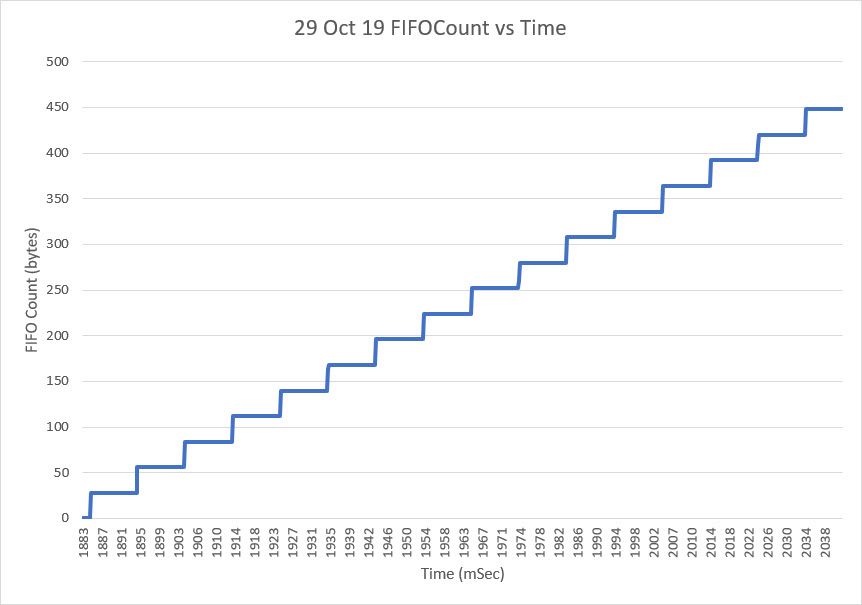
The stairsteps in the above plot are (almost) uniformly the expected packet size of 28 bytes; the MPU6050 is clearly loading entire 28-byte packets into the FIFO each time, contrary to one of the possibilities I had considered to explain the factor of 2 inconsistency between the interrupt count and the FIFO count.
However, when I started looking at the time interval between FIFO loads, I got the following plot:
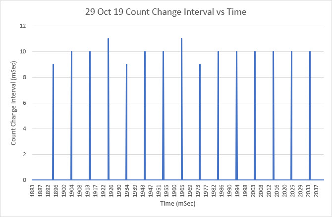
As the above plot clearly shows, the MPU6050 loads a new packet into the FIFO every 10 mSec or so (I think it is exactly 10 mSec, with the differences explained by the lack of resolution in the time axis). But wait – the MPU6050 produces an interrupt on the Arduino interrupt pin every 5 mSec – not every 10 mSec! So, the mystery of the ‘factor of 2’ error is now solved. The MPU6050 loads a new packet into the FIFO every other interrupt – not every interrupt as expected. So, the interrupt count is too high by a factor of 2 when compared to the actual FIFO count.
Unfortunately (or fortunately depending on one’s point of view), that simply begs the question – why is the MPU6050 producing interrupts on a 5 mSec schedule when it only changes the FIFO count on a 10 mSec schedule? Who knows?
Changing the subject slightly, I got another ‘overflow proof’ version of GetCurrentFIFOPacket() from Homer Creutz to try. I set up a small program to test it. Since the idea was that GetCurrentFIFOPacket() would return a valid packet no matter how long it had been since the last time it was called, I set up a program to iterate through a sequence of delay times from 100 mSec to 500 mSec. For each loop delay setting I called GetCurrentFIFOPacket() multiple times and printed out the extracted yaw value and the return status from the function.
As the plot below shows, everything works swimmingly up to a loop delay of 350 mSec. Unfortunately, the wheels came off with a 400 mSec loop delay, and the packet values were all invalid after that – bummer!
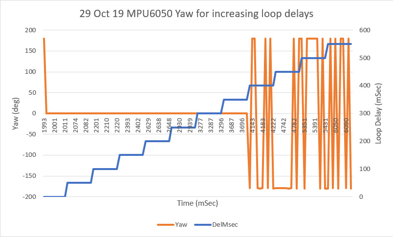
06 November 2019 Update:
Holy cow! Homer and I started this marathon project back in mid October, and we don’t seem to be any closer to nirvana than we were before. What I can say though, is that I have learned a lot more about the MPU6050 and Jeff Rowberg’s driver software ;-).
One of the major issues we encountered with the polling method (vs interrupt-driven) is that, without the synchronization with MPU6050’s internal processes provided by the interrupt model, we can’t count on (no pun intended) the FIFO count returned by mpu.getFIFOCount() being accurate. Depending on the timing of the call, the return value could be wildly inaccurate. However, we discovered that two back-to-back calls to mpu.getFIFOCount() always resulted in an accurate count, although there was still a very small probability that a 3rd call would be required. So, I created a small routine called ‘getPollingFIFOCount()’ to wrap this construct, as follows:
|
1 2 3 4 5 6 7 8 9 10 11 12 13 14 |
int GetPollingFIFOCount(int max_tries) { long int startUsec = micros(); int ctr = 0; int lastFIFOCount = mpu.getFIFOCount(); int fifoC = mpu.getFIFOCount(); while (fifoC != lastFIFOCount && ctr < max_tries) { ctr++; lastFIFOCount = fifoC; } long int endUsec = micros(); return fifoC; } |
This function simply loops until two adjacent calls to mpu.getFIFOCount() return the same value. As always, however, there is a backup counter to force the function to exit if it gets hung up for any reason. In the calling program I have a line like:
|
1 |
const uint16_t MAX_GETPOLLINGFIFOCOUNT_TRIES = 10; //11/03/19 added for backup loop exit condition in GetPollingFIFOCount() |
to set the backup loop counter value.
Another major issue with the MPU6050 is that it can overflow its packet FIFO buffer, and there doesn’t appear to be any way to prevent this, other than removing packets from the FIFO at the same rate or higher than they are loaded. This may not be a problem for ‘high dynamics’ applications like quadcopters or balancing robots that need continuous attitude information, but for ‘slow dynamics’ applications like my wall-following robot where yaw information is only needed a few times per second, overflow becomes a practical certainty. In an interrupt -driven environment, it might be reasonable to simply retrieve and then discard DMP packets as fast as they arrive, and then only process the latest packet when the application needs an update. However, for a polling strategy, doing this may or may not work depending on what else is going on. So, for polling we need a way of ensuring we can retrieve a valid packet from the DMP FIFO, whether or not the FIFO has overflowed. Doing so would be trivial if the FIFO length was an integral multiple of packetSize, but it isn’t – yuk!! So, now when the FIFO overflows, the first packet in the FIFO is guaranteed to be corrupted. The good news is, the last complete packet (i.e. the most recent information) in the FIFO is always valid, but getting to that last good packet is non-trivial. To summarize:
- FIFO overflow is almost certain to happen in a ‘low dynamics’ polling-based program
- When FIFO overflow occurs, the first packet is always corrupted, but the last one is still valid
- The last (valid) packet isn’t the last [packetSize] bytes, due to the non-modular size of the FIFO
- The MPU6050 DMP may start loading another packet at any time, but there will always be 10 mSec or so between packet loads
- Any last-valid-packet retrieval algorithm must work for any loop delay time.
So, the ‘last-valid-packet-retrieval’ algorithm is something like this:
- Get the current packet count, using the ‘getPollingFIFOCount()’ routine above
- Extract [packetSize] chunks until there are less than 2* [packetSize] bytes left. This ensures there is exactly one valid packet remaining in the FIFO.
- Extract one more [packetSize] chunk and return it as the result.
Note that implementation of this algorithm will require several ‘while’ loops, so there must also be provision for forcibly terminating all such loops in case some edge condition causes the normal exit condition to never be reached. Homer and I have been creating and testing versions of this function for the last couple of weeks, without quite getting there yet. Either they don’t handle all the edge conditions, or they are too slow as the loop delays get larger.
While I was testing my most recent concoction, I ran into a third major problem with the MPU6050 API. I wanted to be able to remove up to 35 [packetSize] chunks (980 bytes) in one go, and I expected the mpu.getFIFOBytes() API call to manage the required chunking for me. When I tried this trick, the getFIFOBytes() function crashed repeatedly. Eventually I figured out that the reason it was crashing wa that it’s ‘length’ parameter is declared as a ‘uint8_t’ object and of course it couldn’t handle a value greater than 255 without choking. I thought that was a little odd, but that maybe changing the declaration from ‘uint8_t’ to ‘uint16_t’ in MPU6050.h/cpp would solve the problem. Nope – It turns out that, due to the way that the Arduino I2C bus operates, there is a limitation on how many bytes can be transferred across the bus in one operation, and this limit is currently set at 32 bytes. As a result of this fundamental limitation, all the I2CDev functions that use the I2C bus also have the same underlying limitation and all of them have their length parameters declared as ‘uint8_t’. This reminds me of the old pre-scientific myth about the earth resting on the back of a turtle. When the myth was challenged, the defender says “its no use – it’s turtles all the way down”. In our case “it’s no use – it’s uint8_t all the way down!”.
So, I had to figure out a way around this problem, so I decided to create yet another wrapper function, this one cleverly called ‘getManyFIFOBytes()’. The idea for this would be to pull one [packetSize] chunk off the FIFO at a time using the normal ‘mpu.getFIFOBytes()’ call and place the result in a destination buffer large enough to hold the entire result. Since it has been a (long, long) while since I last played with pointer gymnastics, I decided to write a short test program to figure out a reasonable technique. Here is the program, and some results:
|
1 2 3 4 5 6 7 8 9 10 11 12 13 14 15 16 17 18 19 20 21 22 23 24 25 26 27 28 29 30 31 32 33 34 35 36 37 38 39 40 41 42 43 44 45 46 47 48 49 50 51 52 53 54 55 56 57 58 59 60 61 62 63 64 65 66 67 68 69 70 71 72 73 74 75 76 77 78 79 80 81 82 83 84 85 86 87 88 89 90 91 92 93 94 |
/* Name: MPU6050_PointerTest.ino Created: 11/5/2019 9:47:24 PM Author: FRANKWIN10\Frank */ /* Short program to test the idea of creating a 'getManyFIFOBytes() function to work around the current 8-bit length limitation imposed by mpu.getFIFOBytes(buffer, length) the idea is to retrieve 'packetSize' chunks until less than packetSize remains, then 1 byte at a time until the requested length has been retrieved. */ #include <PrintEx.h> PrintEx mySerial(Serial); const uint16_t packetSize = 28; //const int BUFFER_SIZE = 1024; const int BUFFER_SIZE = 320; //shortened for printout convenience uint16_t buffer[BUFFER_SIZE]; uint8_t other1[packetSize] ; void setup() { Serial.begin(115200); delay(100); mySerial.printf("Short program to demonstrate ability to retrieve arbitrary number of bytes from MPU6050\n"); //set up the test buffer and simulated packet array Serial.println("Create and display test buffer contents..."); mySerial.printf("Simulated large destination buffer\n"); for (size_t i = 0; i < BUFFER_SIZE; i++) { buffer[i] = i; mySerial.printf("%d\n",buffer[i]); } Serial.println("Simulated packet contents..."); for (size_t i = 0; i < packetSize; i++) { other1[i] = packetSize - 1 - i; mySerial.printf("%d\n",other1[i]); } //simulated function to pull 300 bytes from MPU6050 uint16_t numbytes = 300; mySerial.printf("\nSimulate requesting %d bytes from MPU6050\n", numbytes); getManyFIFOBytes(buffer, numbytes); //display modified destination buffer contents Serial.println("Now display the results..."); mySerial.printf("Index\tBuffer\n"); for (size_t i = 0; i < BUFFER_SIZE; i++) { mySerial.printf("%d\t%d\n", i, buffer[i]); } } void loop() { } //11/05/19 hack to get around mpu.getFIFOBytes() 8-bit length parameter limitation uint8_t getManyFIFOBytes(uint16_t* buffer, uint16_t len) { uint16_t bytesremaining = len; uint16_t* ptr = buffer; uint8_t* other1_ptr = other1; mySerial.printf("getManyFIFOBytes(%d): retrieving %d packetSize chunks of %d bytes plus %d bytes\n", len,bytesremaining/packetSize, packetSize, bytesremaining%packetSize); while (bytesremaining >= packetSize) { //simulate pulling a full packet from MPU6050 for (size_t i = 0; i < packetSize; i++) { ptr[i] = other1[i]; } ptr += packetSize; bytesremaining -= packetSize; } //simulate pulling bytesremaining % packetSize from MPU6050 while (bytesremaining > 0) { *ptr++ = *other1_ptr++; bytesremaining --; } } |
|
1 2 3 4 5 6 7 8 9 10 11 12 13 14 15 16 17 18 19 20 21 22 23 24 25 26 27 28 29 30 31 32 33 34 35 36 37 38 39 40 41 42 43 44 45 46 47 48 49 50 51 52 53 54 55 56 57 58 59 60 61 62 63 64 65 66 67 68 69 70 71 72 73 74 75 76 77 78 79 80 81 82 83 84 85 86 87 88 89 90 91 92 93 94 95 96 97 98 99 100 101 102 103 104 105 106 107 108 109 110 111 112 113 114 115 116 117 118 119 120 121 122 123 124 125 126 127 128 129 130 131 132 133 134 135 136 137 138 139 140 141 142 143 144 145 146 147 148 149 150 151 152 153 154 155 156 157 158 159 160 161 162 163 164 165 166 167 168 169 170 171 172 173 174 175 176 177 178 179 180 181 182 183 184 185 186 187 188 189 190 191 192 193 194 195 196 197 198 199 200 201 202 203 204 205 206 207 208 209 210 211 212 213 214 215 216 217 218 219 220 221 222 223 224 225 226 227 228 229 230 231 232 233 234 235 236 237 238 239 240 241 242 243 244 245 246 247 248 249 250 251 252 253 254 255 256 257 258 259 260 261 262 263 264 265 266 267 268 269 270 271 272 273 274 275 276 277 278 279 280 281 282 283 284 285 286 287 288 289 290 291 292 293 294 295 296 297 298 299 300 301 302 303 304 305 306 307 308 309 310 311 312 313 314 315 316 317 318 319 320 321 322 323 324 325 326 327 328 329 330 331 332 333 334 335 336 337 338 339 340 341 342 343 344 345 346 347 348 349 350 351 352 353 354 355 356 357 358 359 360 361 362 363 364 365 366 367 368 369 370 371 372 373 374 375 376 377 378 379 380 381 382 383 384 385 386 387 388 389 390 391 392 393 394 395 396 397 398 399 400 401 402 403 404 405 406 407 408 409 410 411 412 413 414 415 416 417 418 419 420 421 422 423 424 425 426 427 428 429 430 431 432 433 434 435 436 437 438 439 440 441 442 443 444 445 446 447 448 449 450 451 452 453 454 455 456 457 458 459 460 461 462 463 464 465 466 467 468 469 470 471 472 473 474 475 476 477 478 479 480 481 482 483 484 485 486 487 488 489 490 491 492 493 494 495 496 497 498 499 500 501 502 503 504 505 506 507 508 509 510 511 512 513 514 515 516 517 518 519 520 521 522 523 524 525 526 527 528 529 530 531 532 533 534 535 536 537 538 539 540 541 542 543 544 545 546 547 548 549 550 551 552 553 554 555 556 557 558 559 560 561 562 563 564 565 566 567 568 569 570 571 572 573 574 575 576 577 578 579 580 581 582 583 584 585 586 587 588 589 590 591 592 593 594 595 596 597 598 599 600 601 602 603 604 605 606 607 608 609 610 611 612 613 614 615 616 617 618 619 620 621 622 623 624 625 626 627 628 629 630 631 632 633 634 635 636 637 638 639 640 641 642 643 644 645 646 647 648 649 650 651 652 653 654 655 656 657 658 659 660 661 662 663 664 665 666 667 668 669 670 671 672 673 674 675 676 677 678 679 |
Opening port Port open Short program to demonstrate ability to retrieve arbitrary number of bytes from MPU6050 Create and display test buffer contents... Simulated large destination buffer 0 1 2 3 4 5 6 7 8 9 10 11 12 13 14 15 16 17 18 19 20 21 22 23 24 25 26 27 28 29 30 31 32 33 34 35 36 37 38 39 40 41 42 43 44 45 46 47 48 49 50 51 52 53 54 55 56 57 58 59 60 61 62 63 64 65 66 67 68 69 70 71 72 73 74 75 76 77 78 79 80 81 82 83 84 85 86 87 88 89 90 91 92 93 94 95 96 97 98 99 100 101 102 103 104 105 106 107 108 109 110 111 112 113 114 115 116 117 118 119 120 121 122 123 124 125 126 127 128 129 130 131 132 133 134 135 136 137 138 139 140 141 142 143 144 145 146 147 148 149 150 151 152 153 154 155 156 157 158 159 160 161 162 163 164 165 166 167 168 169 170 171 172 173 174 175 176 177 178 179 180 181 182 183 184 185 186 187 188 189 190 191 192 193 194 195 196 197 198 199 200 201 202 203 204 205 206 207 208 209 210 211 212 213 214 215 216 217 218 219 220 221 222 223 224 225 226 227 228 229 230 231 232 233 234 235 236 237 238 239 240 241 242 243 244 245 246 247 248 249 250 251 252 253 254 255 256 257 258 259 260 261 262 263 264 265 266 267 268 269 270 271 272 273 274 275 276 277 278 279 280 281 282 283 284 285 286 287 288 289 290 291 292 293 294 295 296 297 298 299 300 301 302 303 304 305 306 307 308 309 310 311 312 313 314 315 316 317 318 319 Simulated packet contents... 27 26 25 24 23 22 21 20 19 18 17 16 15 14 13 12 11 10 9 8 7 6 5 4 3 2 1 0 Simulate requesting 300 bytes from MPU6050 getManyFIFOBytes(300): retrieving 10 packetSize chunks of 28 bytes plus 20 bytes Now display the results... Index Buffer 0 27 1 26 2 25 3 24 4 23 5 22 6 21 7 20 8 19 9 18 10 17 11 16 12 15 13 14 14 13 15 12 16 11 17 10 18 9 19 8 20 7 21 6 22 5 23 4 24 3 25 2 26 1 27 0 28 27 29 26 30 25 31 24 32 23 33 22 34 21 35 20 36 19 37 18 38 17 39 16 40 15 41 14 42 13 43 12 44 11 45 10 46 9 47 8 48 7 49 6 50 5 51 4 52 3 53 2 54 1 55 0 56 27 57 26 58 25 59 24 60 23 61 22 62 21 63 20 64 19 65 18 66 17 67 16 68 15 69 14 70 13 71 12 72 11 73 10 74 9 75 8 76 7 77 6 78 5 79 4 80 3 81 2 82 1 83 0 84 27 85 26 86 25 87 24 88 23 89 22 90 21 91 20 92 19 93 18 94 17 95 16 96 15 97 14 98 13 99 12 100 11 101 10 102 9 103 8 104 7 105 6 106 5 107 4 108 3 109 2 110 1 111 0 112 27 113 26 114 25 115 24 116 23 117 22 118 21 119 20 120 19 121 18 122 17 123 16 124 15 125 14 126 13 127 12 128 11 129 10 130 9 131 8 132 7 133 6 134 5 135 4 136 3 137 2 138 1 139 0 140 27 141 26 142 25 143 24 144 23 145 22 146 21 147 20 148 19 149 18 150 17 151 16 152 15 153 14 154 13 155 12 156 11 157 10 158 9 159 8 160 7 161 6 162 5 163 4 164 3 165 2 166 1 167 0 168 27 169 26 170 25 171 24 172 23 173 22 174 21 175 20 176 19 177 18 178 17 179 16 180 15 181 14 182 13 183 12 184 11 185 10 186 9 187 8 188 7 189 6 190 5 191 4 192 3 193 2 194 1 195 0 196 27 197 26 198 25 199 24 200 23 201 22 202 21 203 20 204 19 205 18 206 17 207 16 208 15 209 14 210 13 211 12 212 11 213 10 214 9 215 8 216 7 217 6 218 5 219 4 220 3 221 2 222 1 223 0 224 27 225 26 226 25 227 24 228 23 229 22 230 21 231 20 232 19 233 18 234 17 235 16 236 15 237 14 238 13 239 12 240 11 241 10 242 9 243 8 244 7 245 6 246 5 247 4 248 3 249 2 250 1 251 0 252 27 253 26 254 25 255 24 256 23 257 22 258 21 259 20 260 19 261 18 262 17 263 16 264 15 265 14 266 13 267 12 268 11 269 10 270 9 271 8 272 7 273 6 274 5 275 4 276 3 277 2 278 1 279 0 280 27 281 26 282 25 283 24 284 23 285 22 286 21 287 20 288 19 289 18 290 17 291 16 292 15 293 14 294 13 295 12 296 11 297 10 298 9 299 8 300 300 301 301 302 302 303 303 304 304 305 305 306 306 307 307 308 308 309 309 310 310 311 311 312 312 313 313 314 314 315 315 316 316 317 317 318 318 319 319 |
As the output shows, the ‘getManyFIFOBytes(uint16_t* buffer, uint16_t len)’ function can take an arbitrary ‘uint16_t’ length parameter and fill the destination buffer with [packetSize] (28 bytes in this case) chunks, followed by the non-modular remainder. Although this test was done with a simulated receive buffer and simulated packet contents, I believe it will work using the actual contents of the MPU6050 FIFO and repeated calls to ‘mpu.getFIFOBytes()’ to retrieve the ‘chunks’ and any non-modular remainder bytes.
Having convinced myself that my two helper functions actually did what I wanted, I revised my latest MPU6050 test program (MPU6050_Overflow8.ino) to test the whole thing out. The test program steps through a series of loop delays from 50 to 550 msec, and takes 25 yaw measurements at each loop delay setting. The Excel plot and a snippet of the output log from the program is shown below
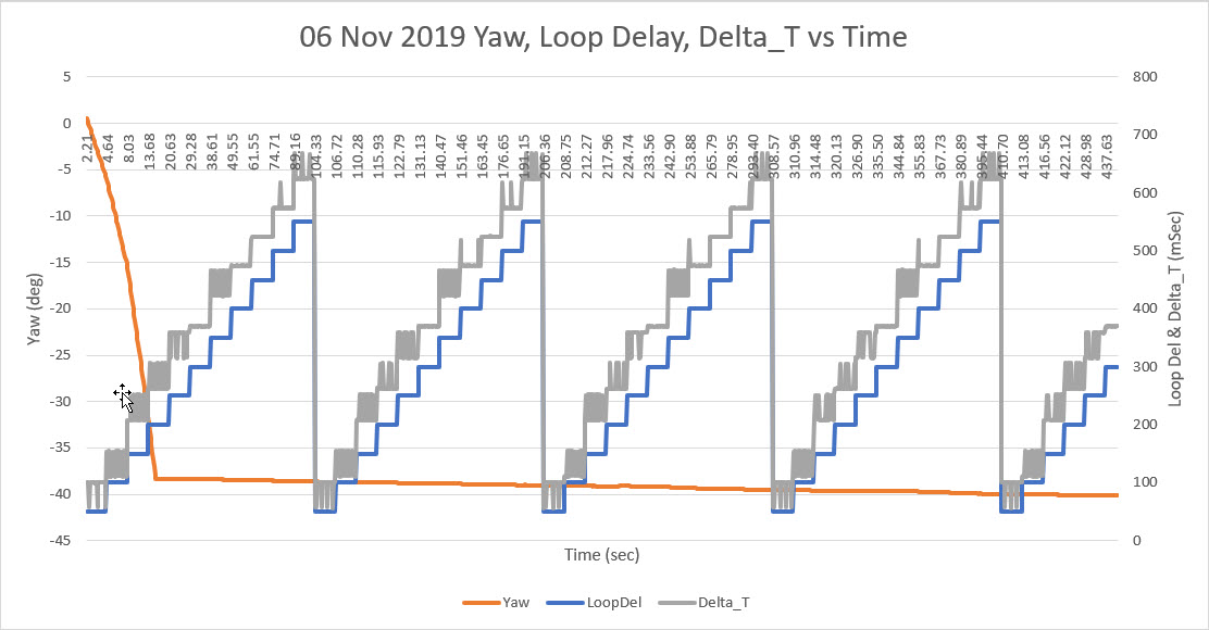
|
1 2 3 4 5 6 7 8 9 10 11 12 13 14 15 16 17 18 19 20 21 |
mSec LoopDel FIFOCtUsec GetPktMsec Yaw Sec Delta_T 11407 150 292 3 -25.17 11.41 208 11658 150 292 3 -25.87 11.66 251 11867 150 296 3 -26.47 11.87 209 12118 150 300 2 -27.17 12.12 251 12325 150 292 3 -27.76 12.33 207 12577 150 292 2 -28.47 12.58 252 12785 150 300 3 -29.07 12.79 208 12998 150 296 1 -29.65 13.00 213 13207 150 292 3 -30.25 13.21 209 13415 150 296 3 -30.83 13.42 208 13677 200 296 3 -31.57 13.68 262 13938 200 292 3 -32.3 13.94 261 14244 200 296 2 -33.17 14.24 306 14505 200 296 4 -33.9 14.51 261 14768 200 296 3 -34.63 14.77 263 15073 200 292 3 -35.51 15.07 305 15335 200 296 3 -36.24 15.34 262 15597 200 292 3 -36.97 15.60 262 15902 200 292 2 -37.84 15.90 305 16164 200 292 3 -38.39 16.16 262 |
- There were no invalid packets in the entire run, so the attempt to avoid invalid packet retrieval was a success.
- The actual loop delay per measurement pass varied quite a bit from the desired loop delay setting. For instance the average measured loop delay for the 25 yaw measurement passes at the 200 mSec loop delay setting was actually 274.08 mSec, almost 50% higher than desired. At the 150 mSec loop delay setting, the average loop delay was 223.88 mSec, and at the 100 mSec setting it was 133.24 mSec. So, if the application needs 5 measurements/sec, the allowable loop delay between passes needs to be between 100 and 150 mSec.
12 November 2019 Update:
Based on some comments and data from Homer’s experiments, it appears that a FIFO reset can be done in less than 10 mSec. This means that a packet retrieval algorithm based on a mpu.resetFIFO() call will miss at most one 10 mSec FIFO load interval, which is insignificant compared to the typical polling interval (200 mSec in my case). So I decided to try a ‘brute force’ approach to ‘GetCurrentFIFOPacket()’ as follows:
|
1 2 3 4 5 6 7 8 9 10 11 12 13 14 15 16 17 18 19 20 21 22 23 24 25 26 27 28 29 30 31 32 33 34 35 36 37 38 39 40 41 42 43 |
uint8_t GetCurrentFIFOPacket(uint8_t *data, uint8_t length, uint16_t max_loops) { //mpu.resetFIFO(); //delay(1); fifoCount = mpu.getFIFOCount(); GetPacketLoopCount = 0; //11/10/19 I have seen this fail with fifoC > 28 on occasion, so now I loop max three times OuterGetPacketLoopCount = 0; while (fifoCount != packetSize && OuterGetPacketLoopCount <= 3) { mpu.resetFIFO(); delay(1); fifoCount = mpu.getFIFOCount(); GetPacketLoopCount = 0; //mySerial.printf("In GetCurrentFIFOPacket: before loop fifoC = %d\t",fifoC); while (fifoCount < packetSize && GetPacketLoopCount < max_loops) { GetPacketLoopCount++; fifoCount = mpu.getFIFOCount(); //delay(2); } if (GetPacketLoopCount >= max_loops) { return 0; } //if we get to here, there should be exactly one packet in the FIFO OuterGetPacketLoopCount++; } if (OuterGetPacketLoopCount < 3) { mpu.getFIFOBytes(data, packetSize); return 1; } return 0; //failed to get a good packet } |
When I first tested this algorithm, I ran into an occasional glitch where the FIFO would somehow fail to reset, resulting in a FIFO count > 28. So I added an outer loop to allow multiple shots at getting a clean FIFO reset.
Shown below are some Excel plots from some long runs
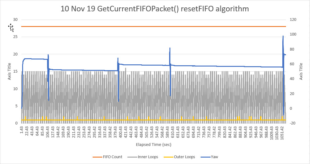
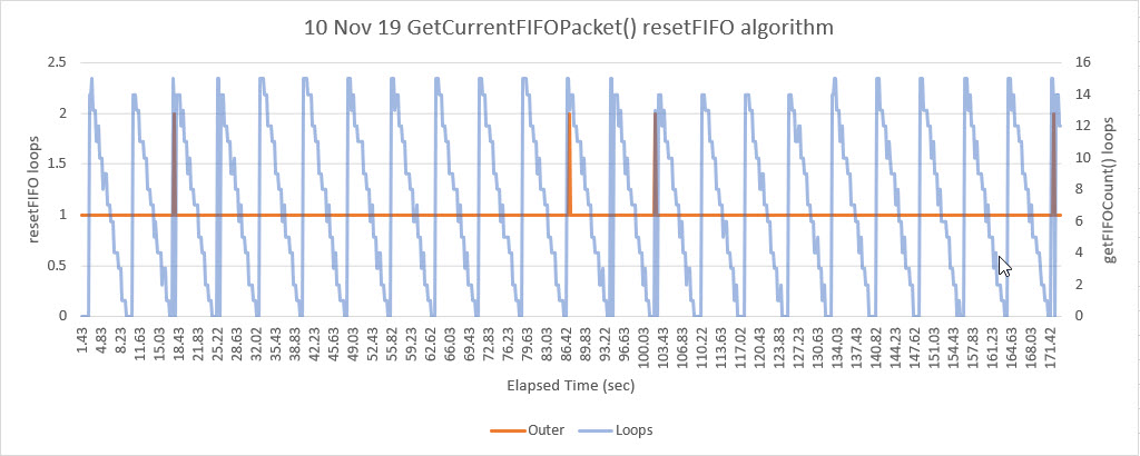
The first plot above shows a long run (over 17 minutes) of valid yaw data (the perturbations in the yaw plot are due to occasional manual rotations of the sensor to verify that the sensor was still responding). The interesting thing about this plot is the yellow curve, showing the ‘outer loop’ count. The only way this value can be greater than 1 is if the first mpu.resetFIFO() call fails to actually clear the FIFO, which appears to happen an average of about once per minute, or about once every 6,000 10 mSec MPU6050 FIFO cycles.
The second plot is a closeup of the first 171.42 seconds of the overall plot, showing the detail of the FIFO clear failures, occurring about once per minute.
So, it is clear that the MPU6050 has some significant behavioral quirks, especially when used in a non-interrupt-driven environment. That being said, I believe the ‘brute force’ algorithm shown above is a reliable way of interfacing with the MPU6050 in a polling environment, and obviates the need for a separate interrupt line, and the associated ISR software.
This will probably be the last update on this subject, as I now think Homer and I have pretty much beat the MPU6050 FIFO issue to death.
Stay tuned!
Frank