Posted 04 November 2016
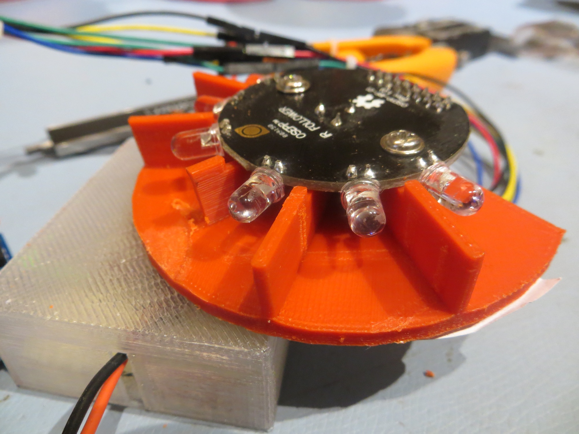
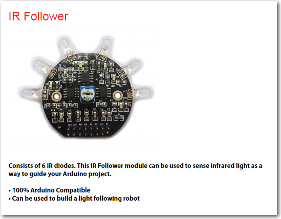
As I described in my previous post on this subject, the OSEPP IR Follower is a nice module, but its IR detector arrangement seems to be ill-suited for my intended application, which is to implement an IR homing capability to allow my wall-following robot to autonomously home in on a charging station so it can recharge its batteries and (hopefully) wander the house indefinitely (or at least until one of the cats figures out how to kill it!).
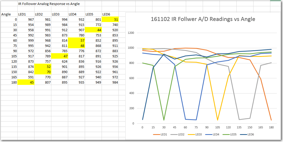
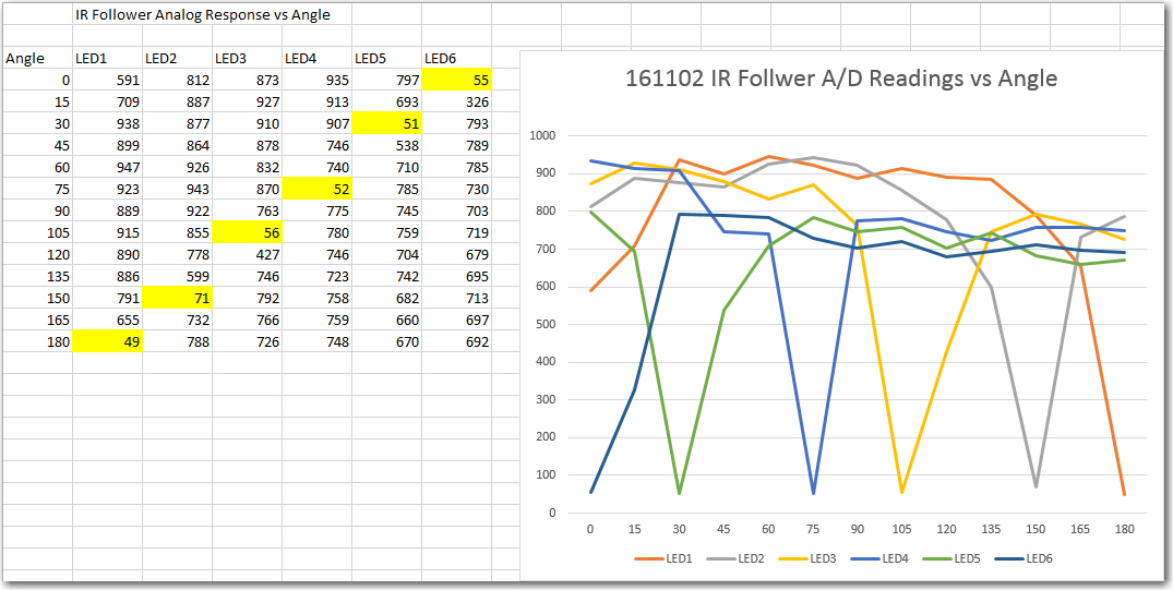
As shown in the following detection vs angle plot for the OSEPP module, there is a dead zone of about 20 º between IR detector beam edges. This dead zone makes it very difficult to determine the proper steering value to feed to the motors for homing, as it is basically impossible to determine which dead zone the IR beacon beam is hitting.
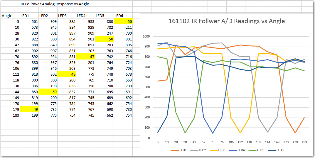
Results from fourth heading tests on bench-top range. For this test, the idea was to determine the approximate beamwidth of each detector
It would be much nicer if the individual IR detector beams overlapped at their respective half-power points, so that dead zones would be completely eliminated. This requires that the beam centers be spaced at the same value as the half-power beamwidths, i.e. about 15 º. So, a six-detector array would span 90 º instead of 180 º
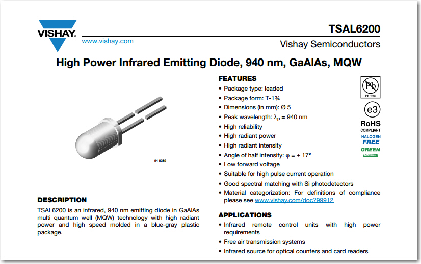
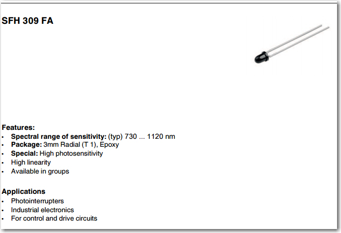
Looking over my electronics parts hoard, I see that I have some Oshram SFH309FA-4 phototransistors on hand that should do the trick, and as a bonus, these units have a 24 º half-sense beamwidth instead of 15 º, which means I can do a 72 º span with just four units – yay!!
OSRAM SFH309FA-4 phototransistor specs, page 1
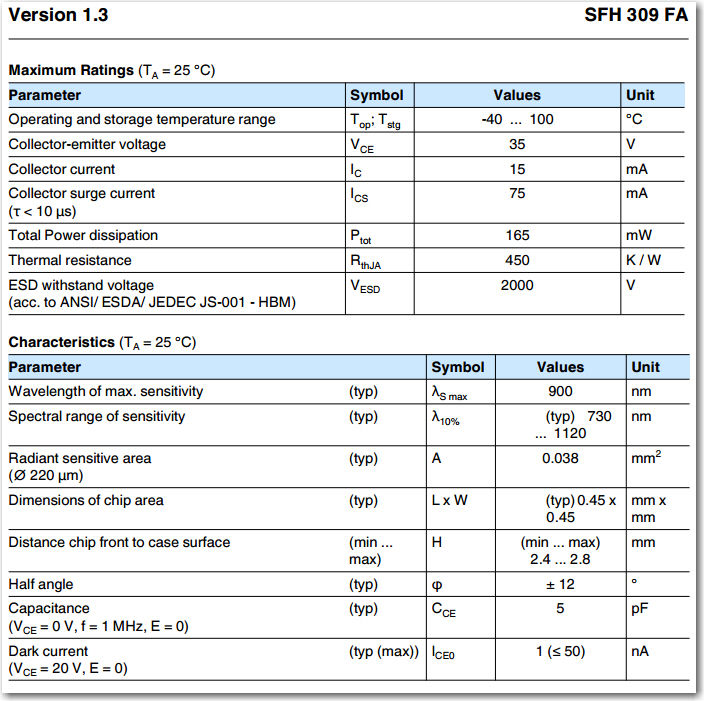
OSRAM SFH309FA-4 phototransistor specs, page 2
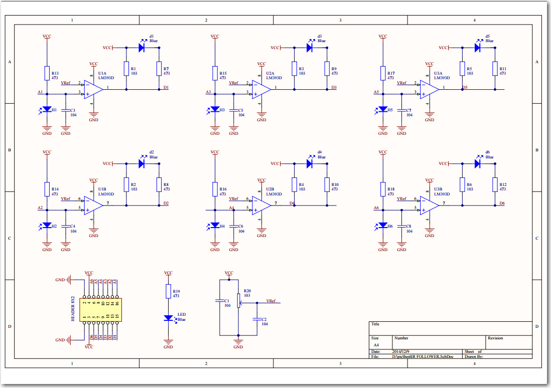
Using the wonderful DipTrace schematic capture package, I whipped up a circuit using 4ea of the above phototransistors, 4ea 1K load resistors, and a 0.1uF noise suppression cap for good measure, as shown below
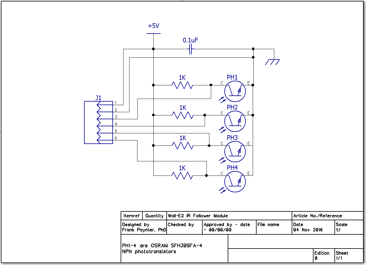
Wall-E2 IR Follower circuit diagram
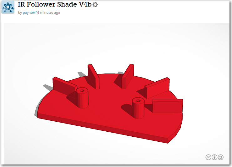
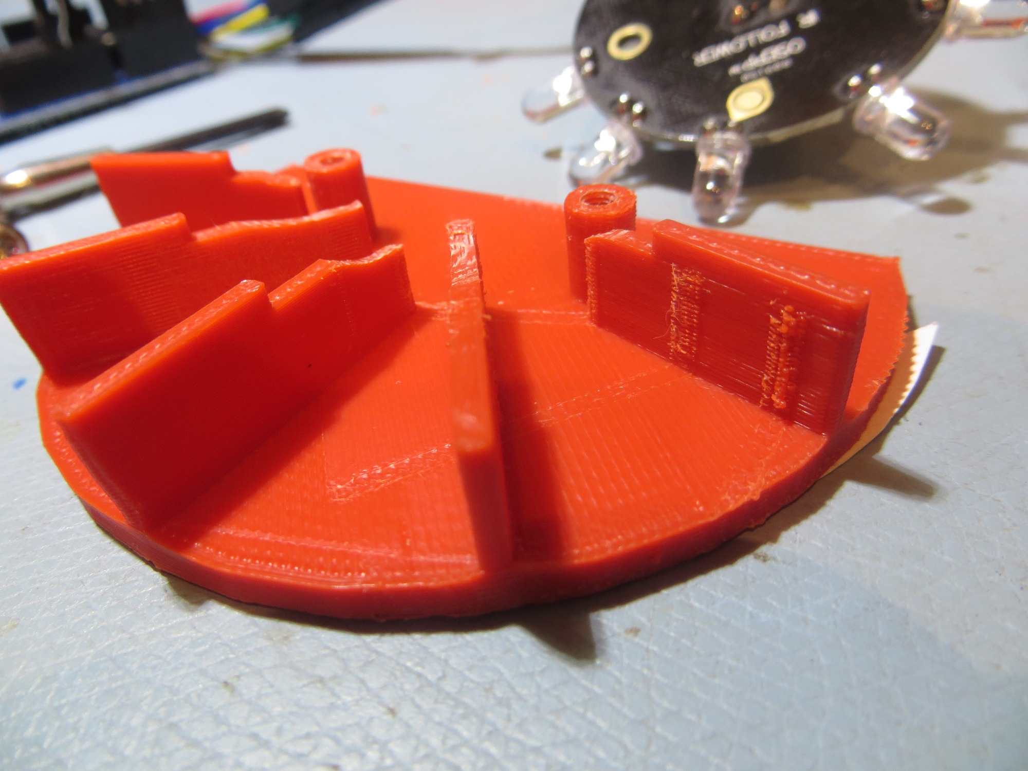
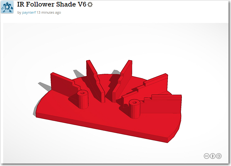
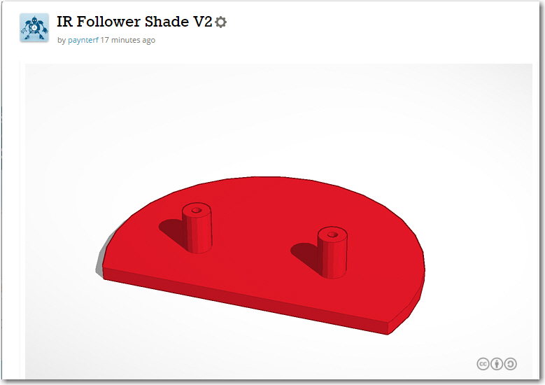
My first try at a module design is shown below. Because the print time is so short (~9 min) and the cost is so trivial, it’s easier and faster to just take a stab at the design, print it, and then repeat as necessary to optimize the solution. The down side, if you can call it that, is that it is so easy to make small adjustments to the design that it is hard to stop – there’s always ‘one more small thing’ that can be done to make the product just a little bit better ;-).
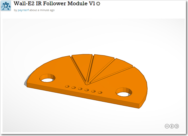
First try at a 4-element IR Follower array
Posted 07 November 2016: USA Presidential Election Eve!
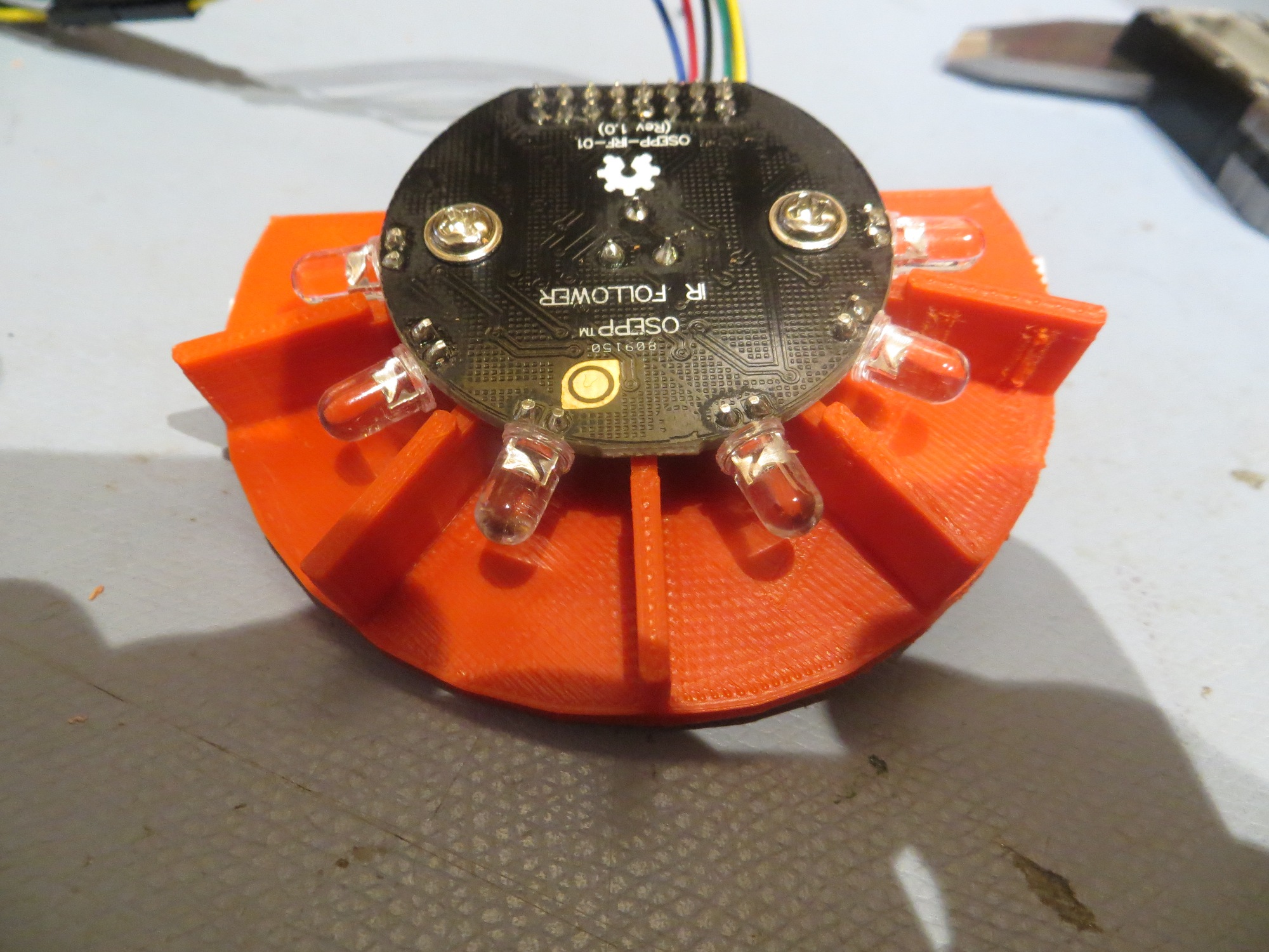
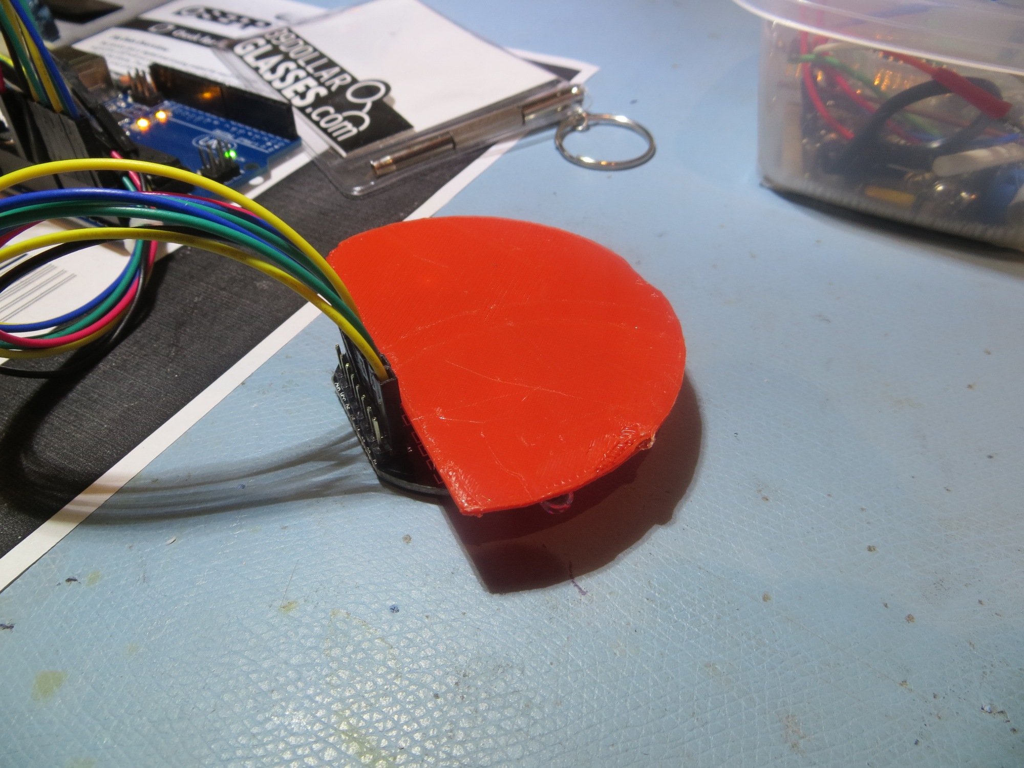
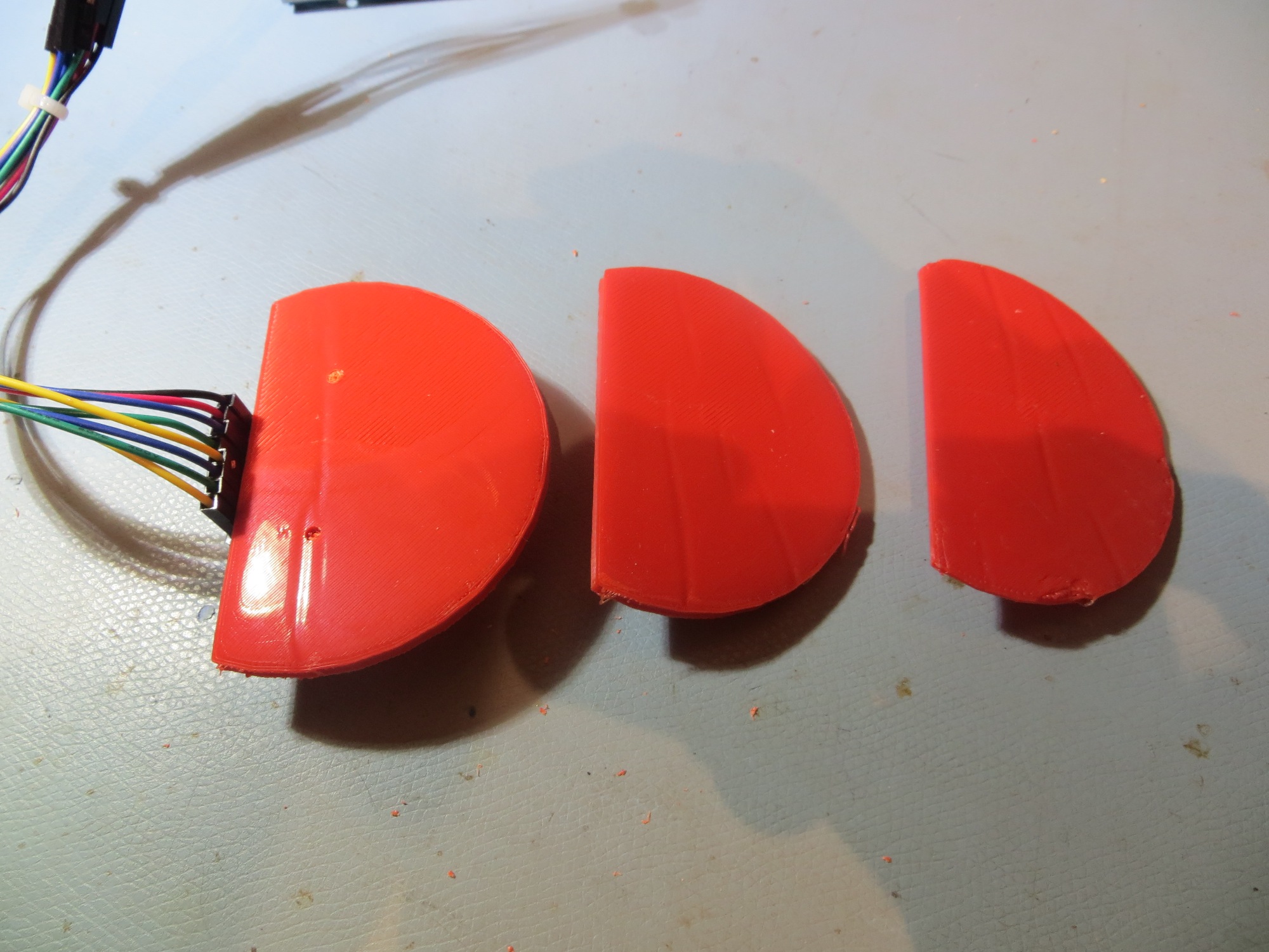
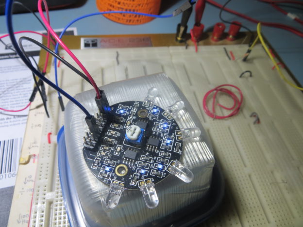
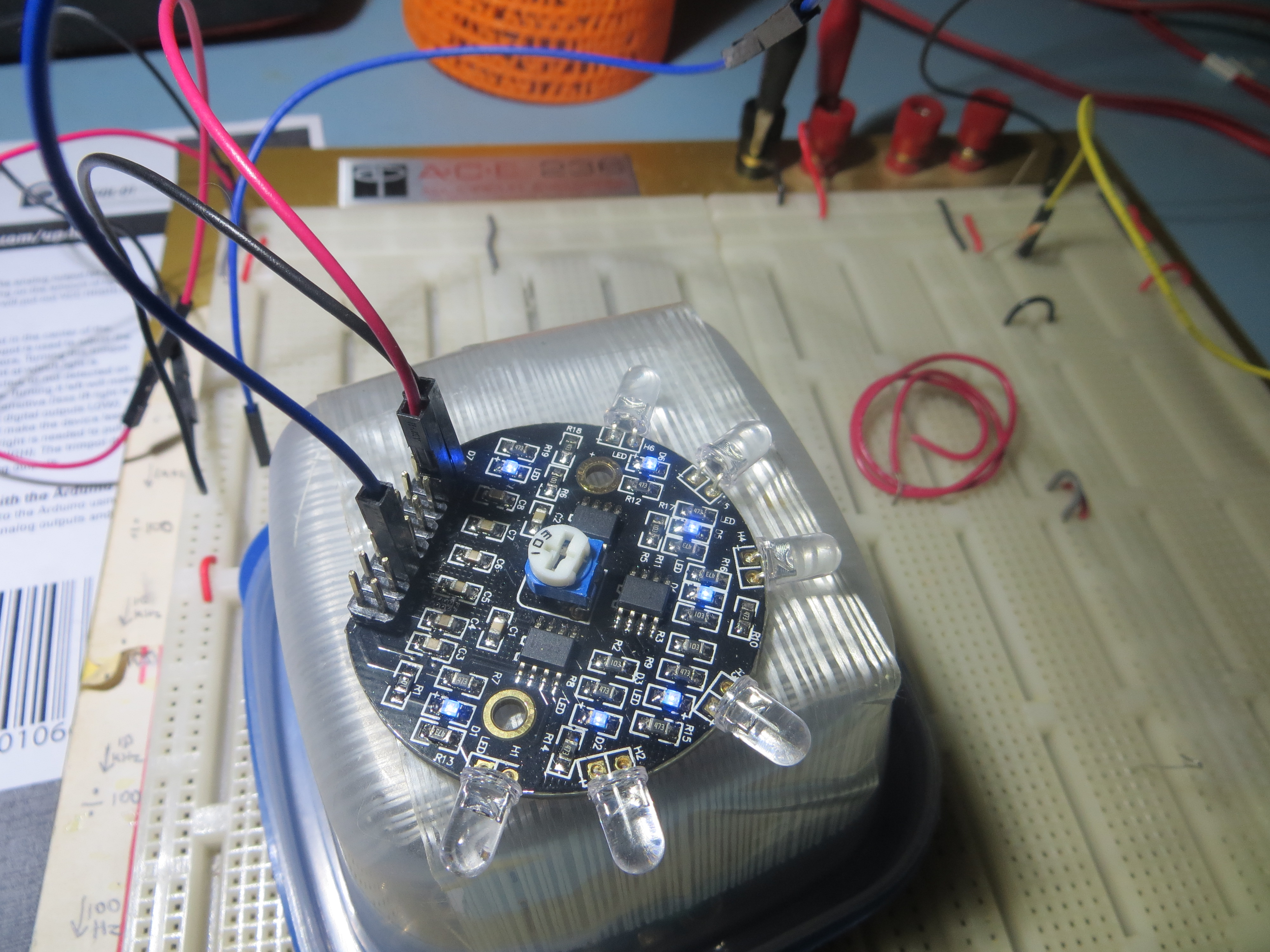
After a few more versions, I had one that I liked. To test the idea, I mounted the new module onto the old ‘sunshade’ just for mechanical stability, and added the 6-pin right-angle header (4 detectors plus pwr & gnd) and one photodetector, as shown here
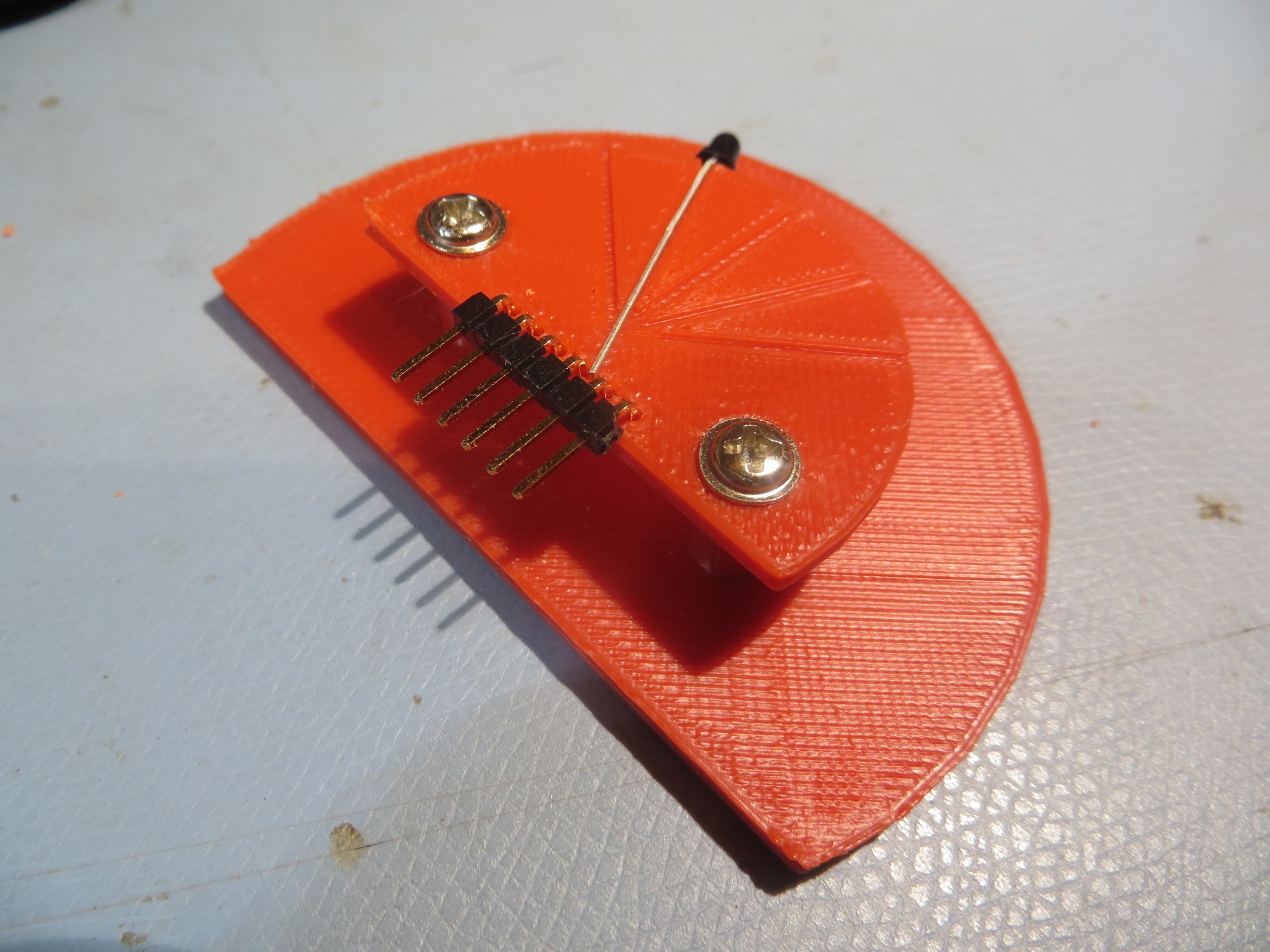
Trial assembly of 4-detector module
This seemed to be OK, so I went ahead and built up the 4-detector module, as shown in the following photos
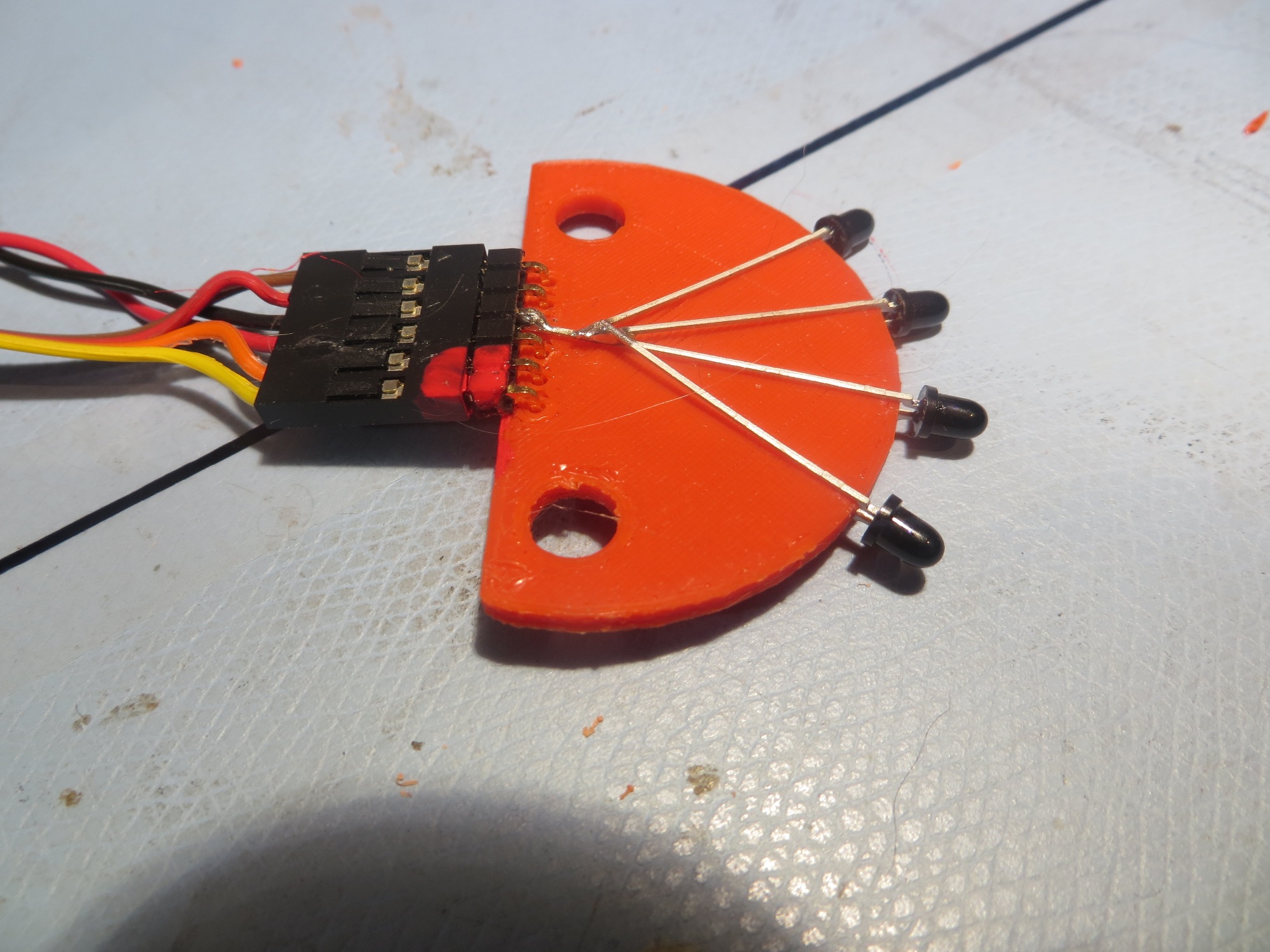
Bottom side of assembled 4-detector module, showing all 4 detector emitters tied to ground
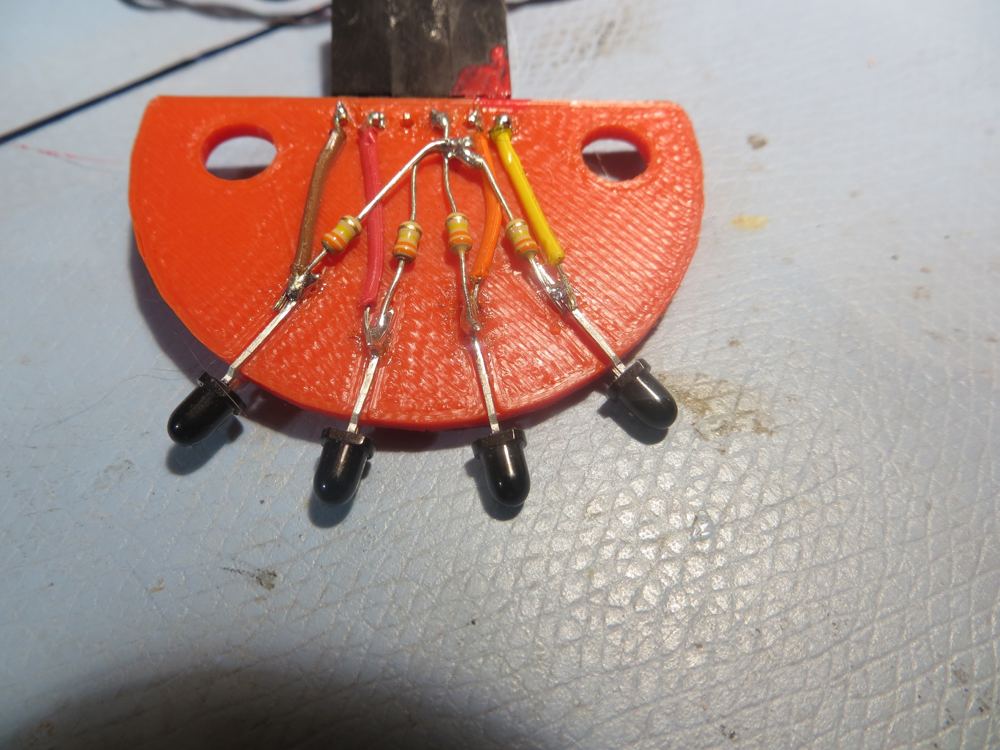
Top view of completed 4-detector module. Note load resistors are now 330K for better sensitivity
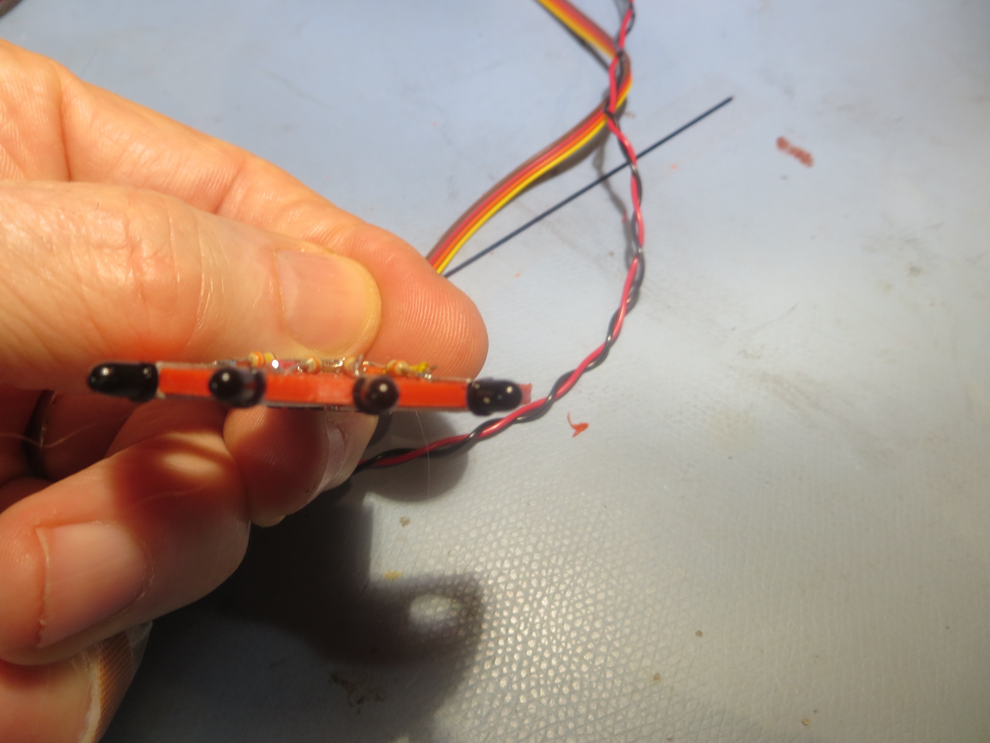
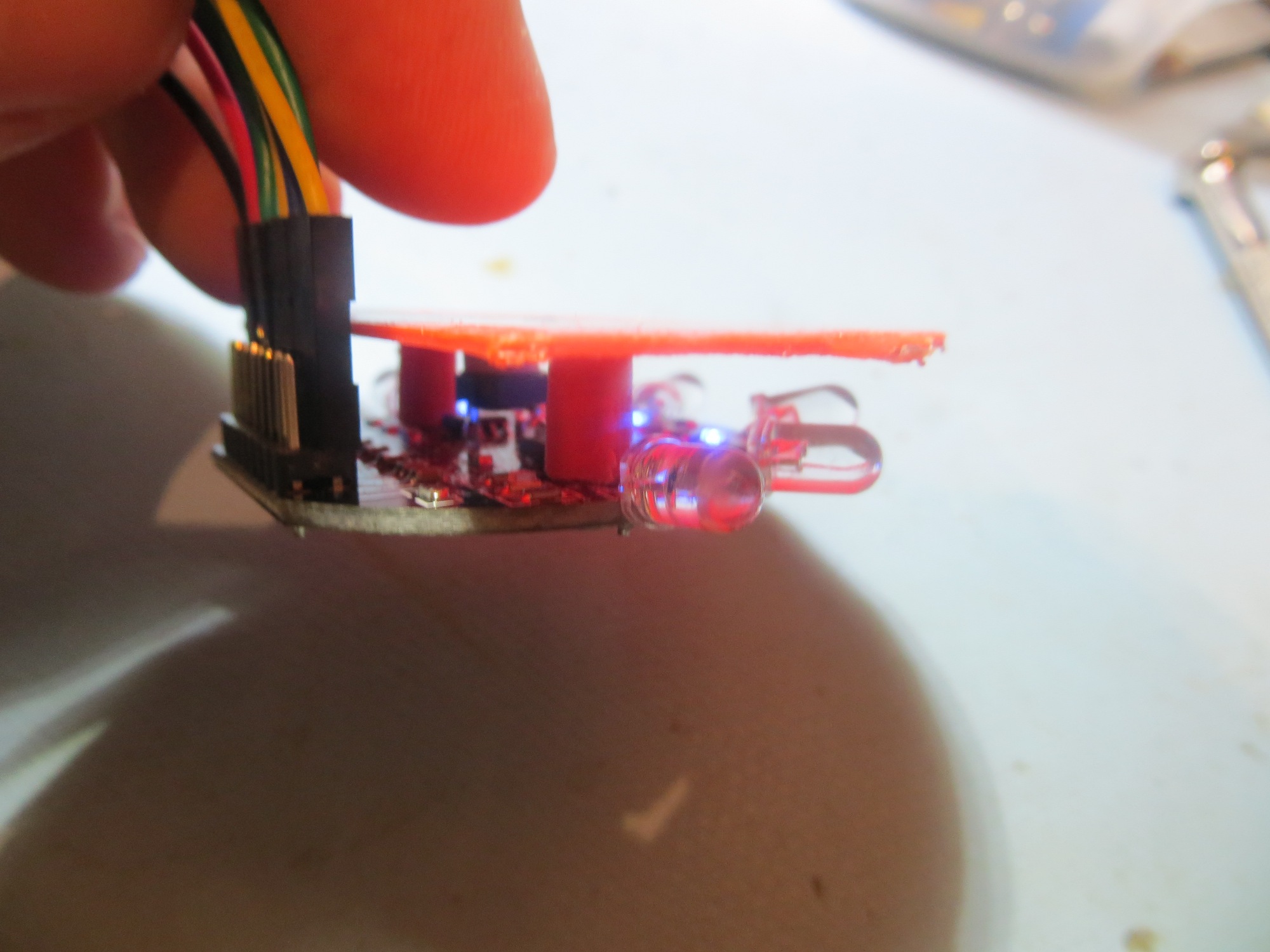
Front edge view of completed 4-detector module
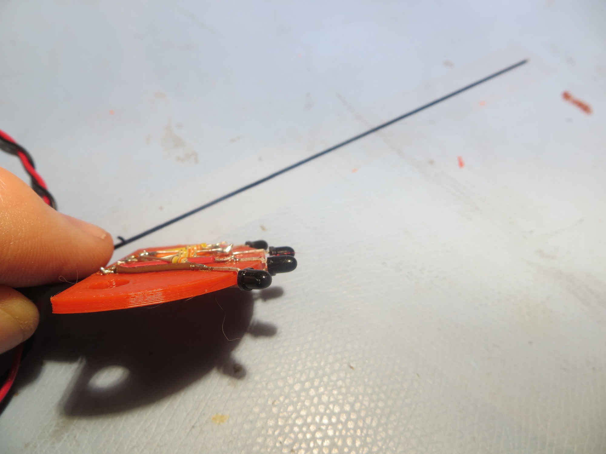
Edge view of completed 4-detector module
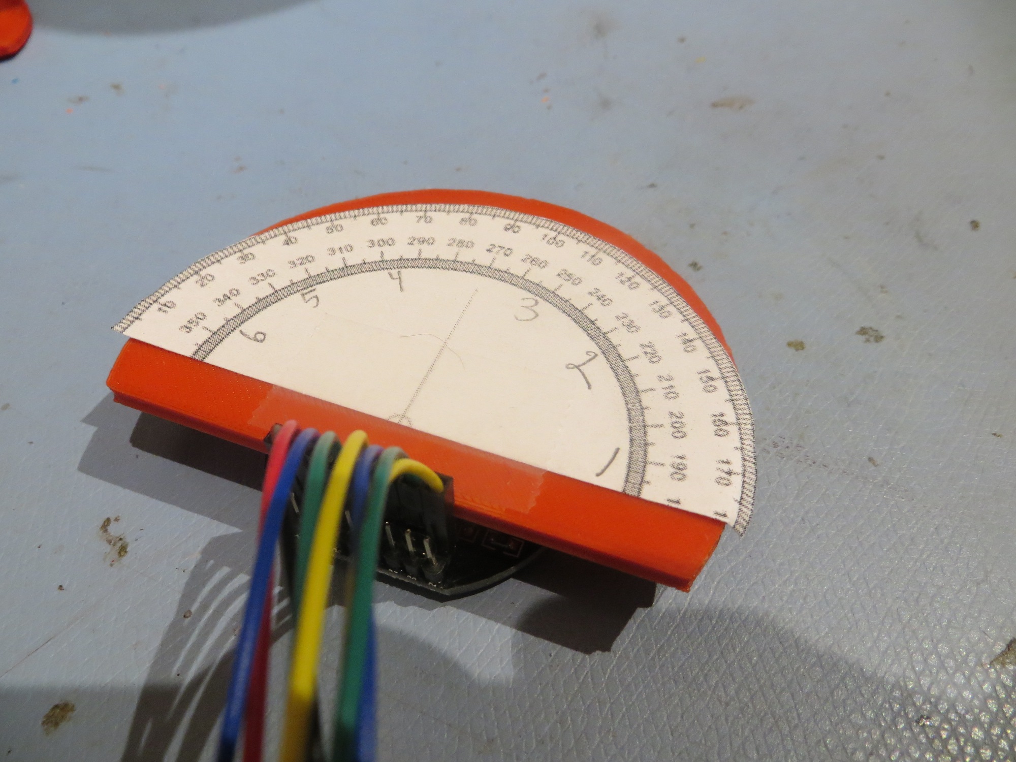
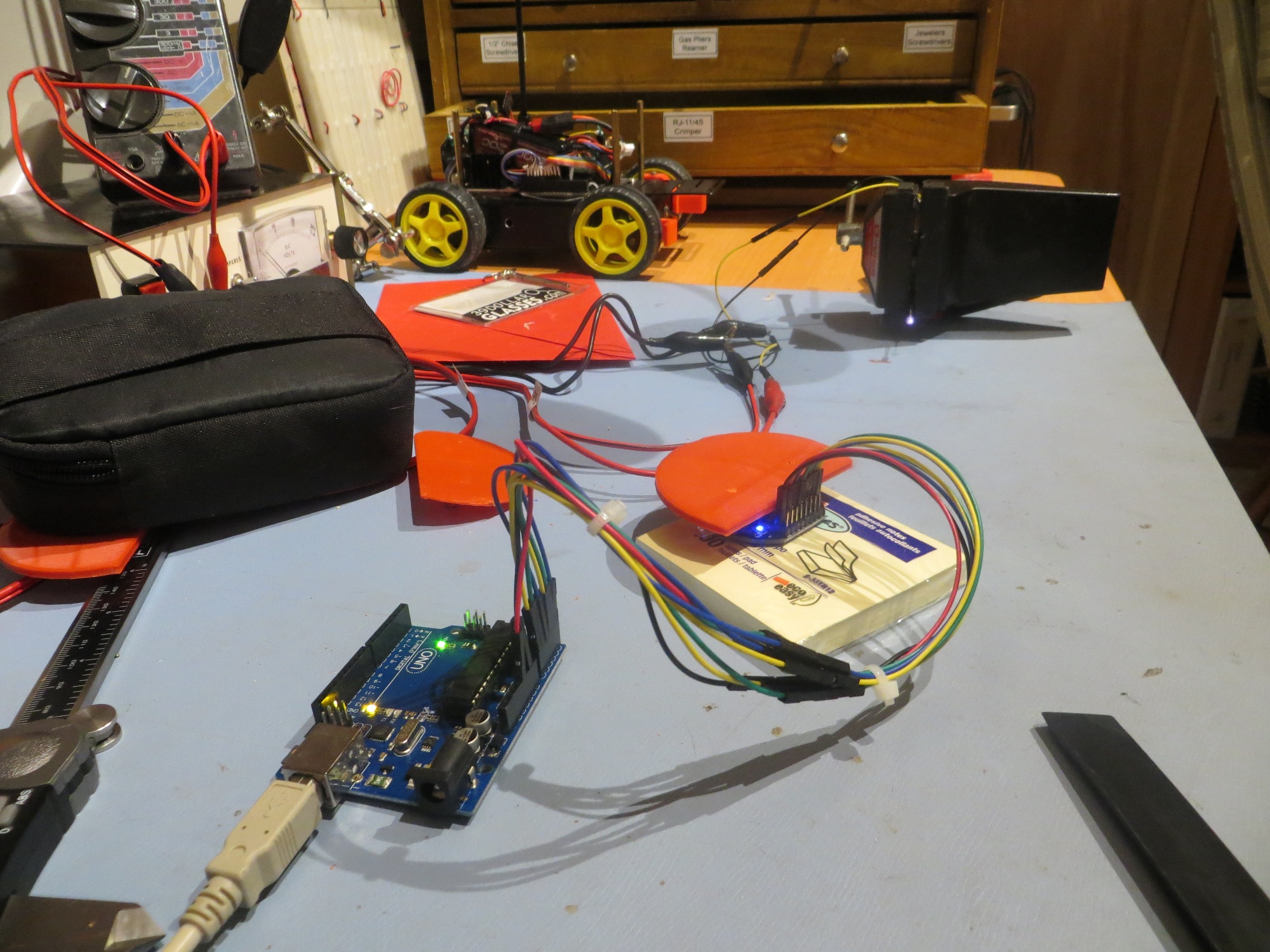
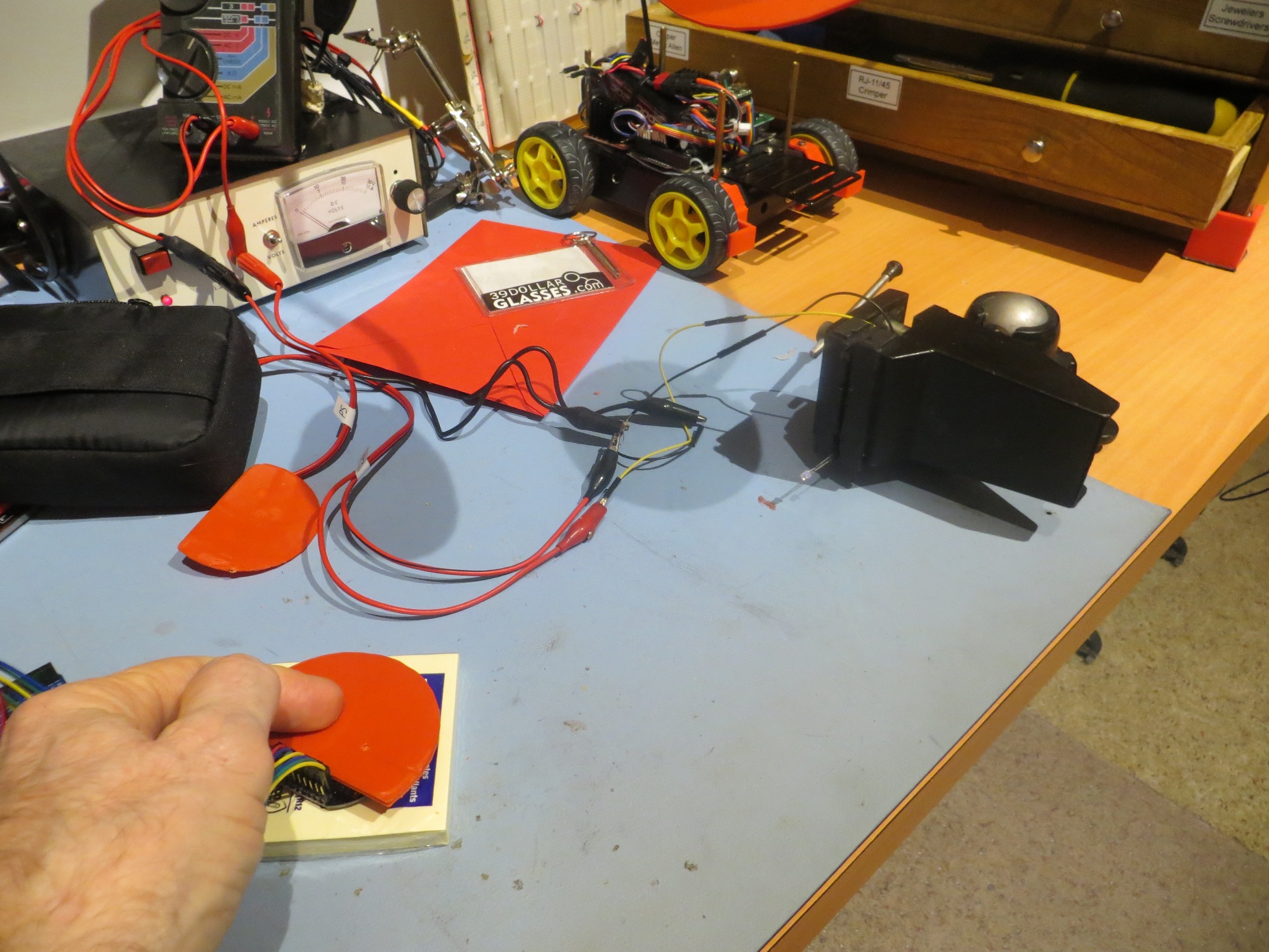
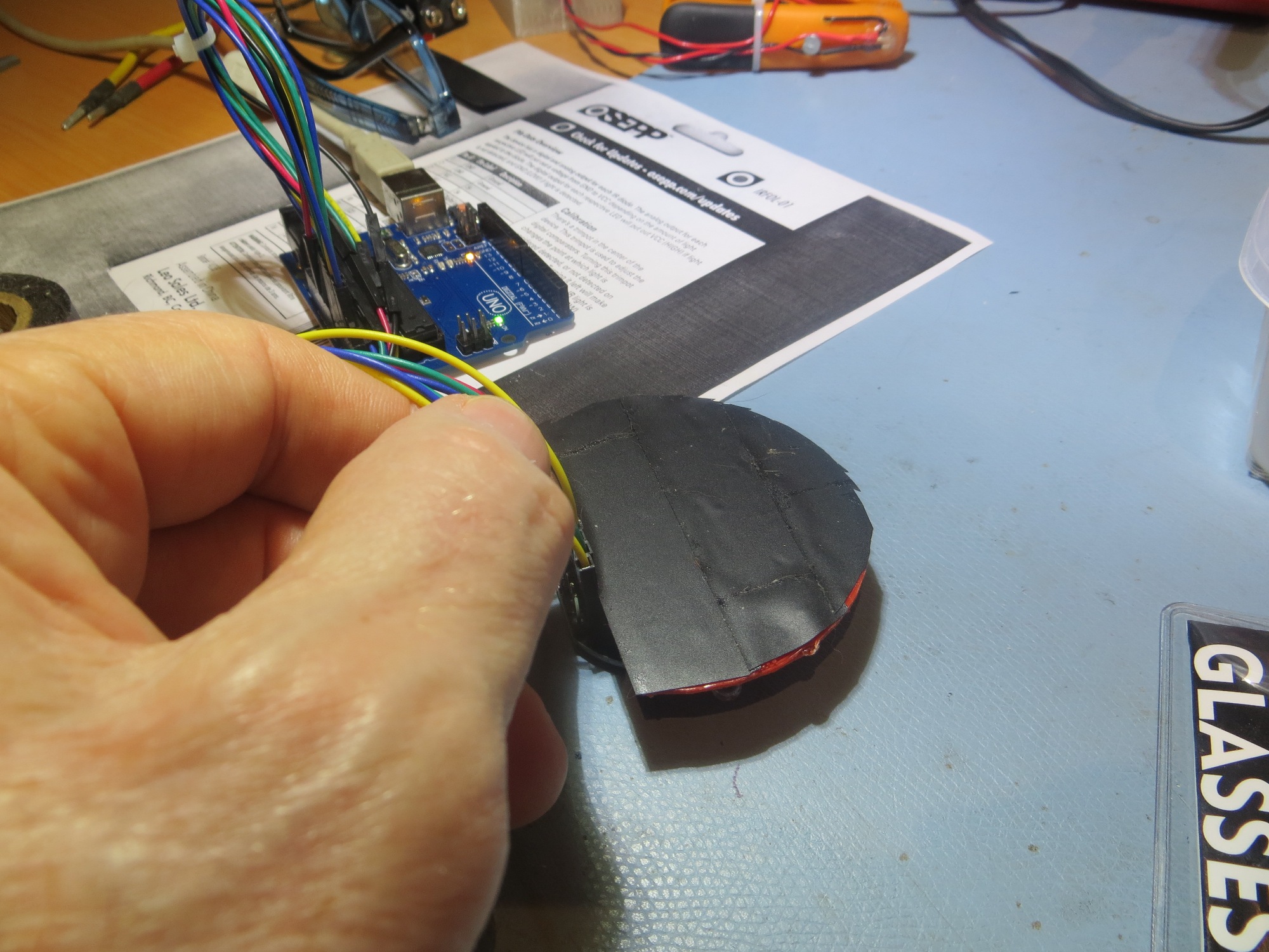
After verifying that the module was indeed operational, I ran a range test at 24″ from the IR LED. I really didn’t have a good way of attaching a heading circle printout to the new module, so I simply taped the 4-detector module to the top of the OSEPP module’s sunshade as shown. This let me use the same heading circle printout I used before – clever if I do say so myself! ;-).
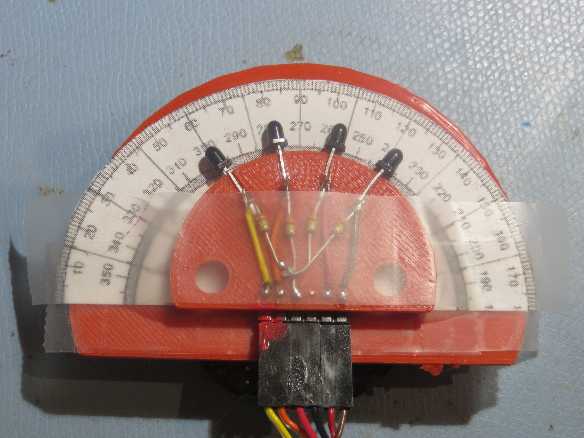
Completed 4-detector module taped to original OSEPP module to utilize existing heading printout
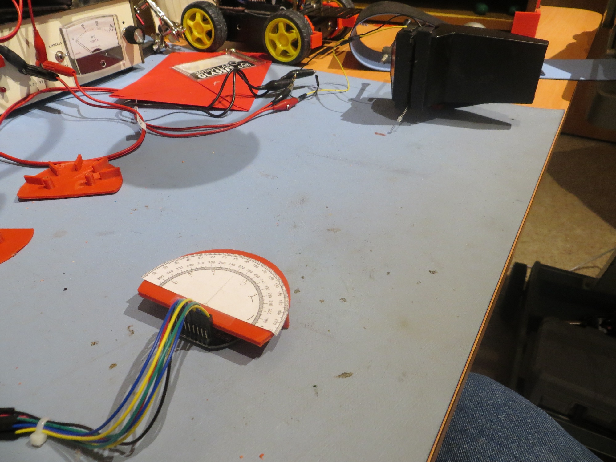
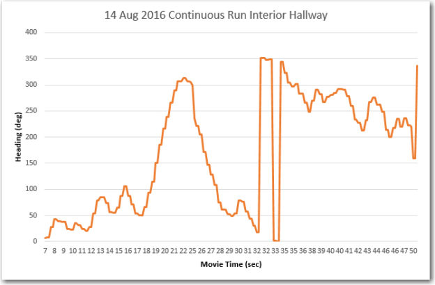
After getting everything working, and modifying the Arduino program for 4 detectors vice 6, I ran a detector output vs angle test at a range of 24″ from the IR emitter, as shown.
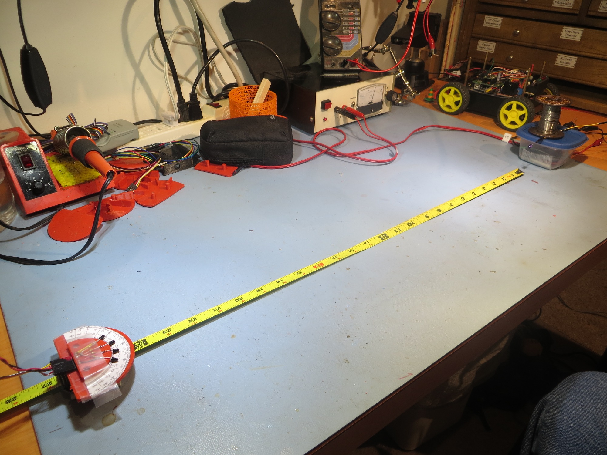
24″ test range for the completed 4-detector module
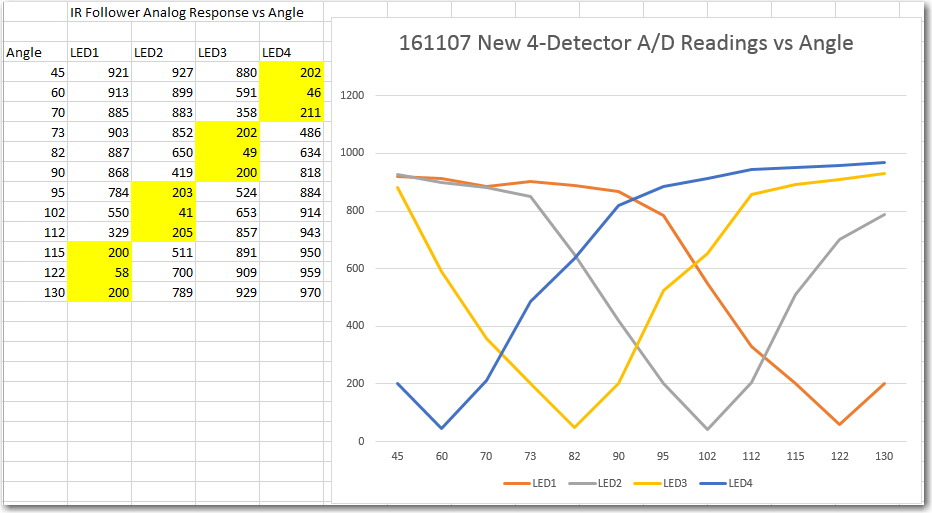
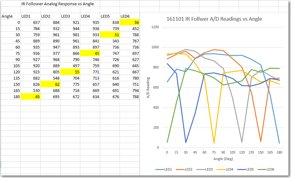
4-detector heading test results
The results came out better than I could have hoped. As can be seen from the data and the plot, I’m getting close to the expected 24 º beamwidth, and it is clear that there are no dead zones between detector minimums. For every angle between 45 º and 130 º there is no ambiguity as to which detector(s) are active, and how to steer to home in on the emitter.
A couple of side notes:
- My original design (see above) used 1K load resistors, but I soon found that to be way too low – the detectors could barely detect the IR emitter from less than 6″ away. After some empirical testing, I finally settled on 330K as a reasonable compromise that allows decent response from approximately 1m away.
- I discovered that the OSRAM photodetectors are not at all sensitive to my LED bench lamps, or to my overhead LED track lighting, due to (I believe) the visible light rejection coating on the detector lens assembly. This means I no longer need the sunshade at all, which should make the physical mounting issue much easier to deal with.
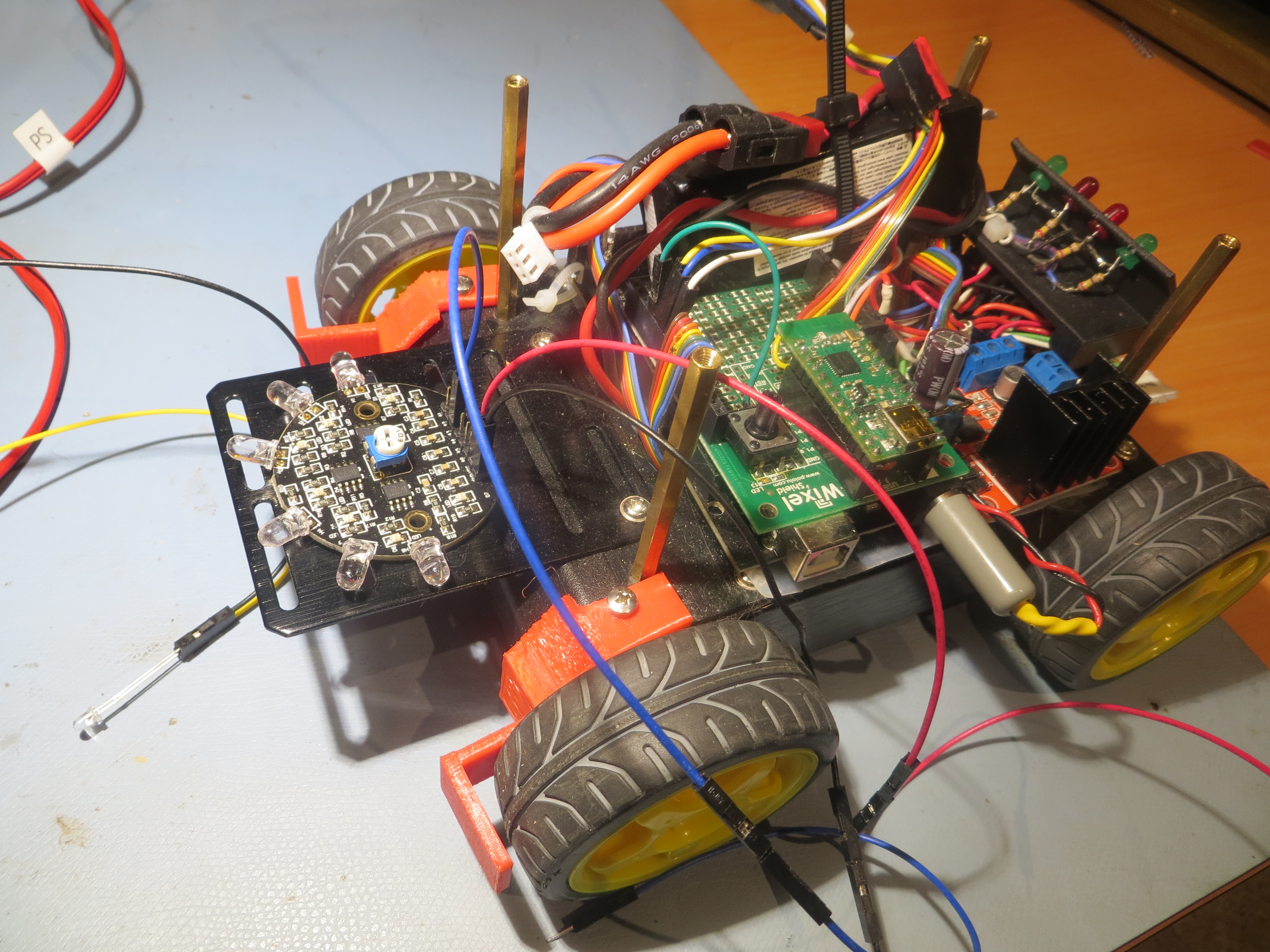
The next step is a big one, and will require a fair amount of work. I’ll need to physically mount the new module on Wall-E2, wire it into the Mega controller, and modify the program to exploit the new capability. At the moment, Wall-E2 is a mild state of dis-repair, so this all may take some time. No worries – I’ve got plenty of that (I hope).