Tag Archives: robots

Charging Station System Integration. Part II

Posted 07 April 2017

After getting the wall-following mode re-implemented in the ‘new-improved’ Wall-E2 operating system, I re-enabled the IR homing part of the code, only to discover that Wall-E2 thought it could see the IR homing beam  everywhere, in the atrium, even though the IR homing LED wasn’t even in the room (and was turned OFF, besides)!  This didn’t make a whole lot of sense, until I realized Wall-E2’s sensors were ‘seeing’ IR from the overhead floodlamps.  I confirmed this by having my ‘lovely assistant’ wife turn the atrium lights on & off and monitoring the detector outputs.  Same thing for the entry hallway (see data below)

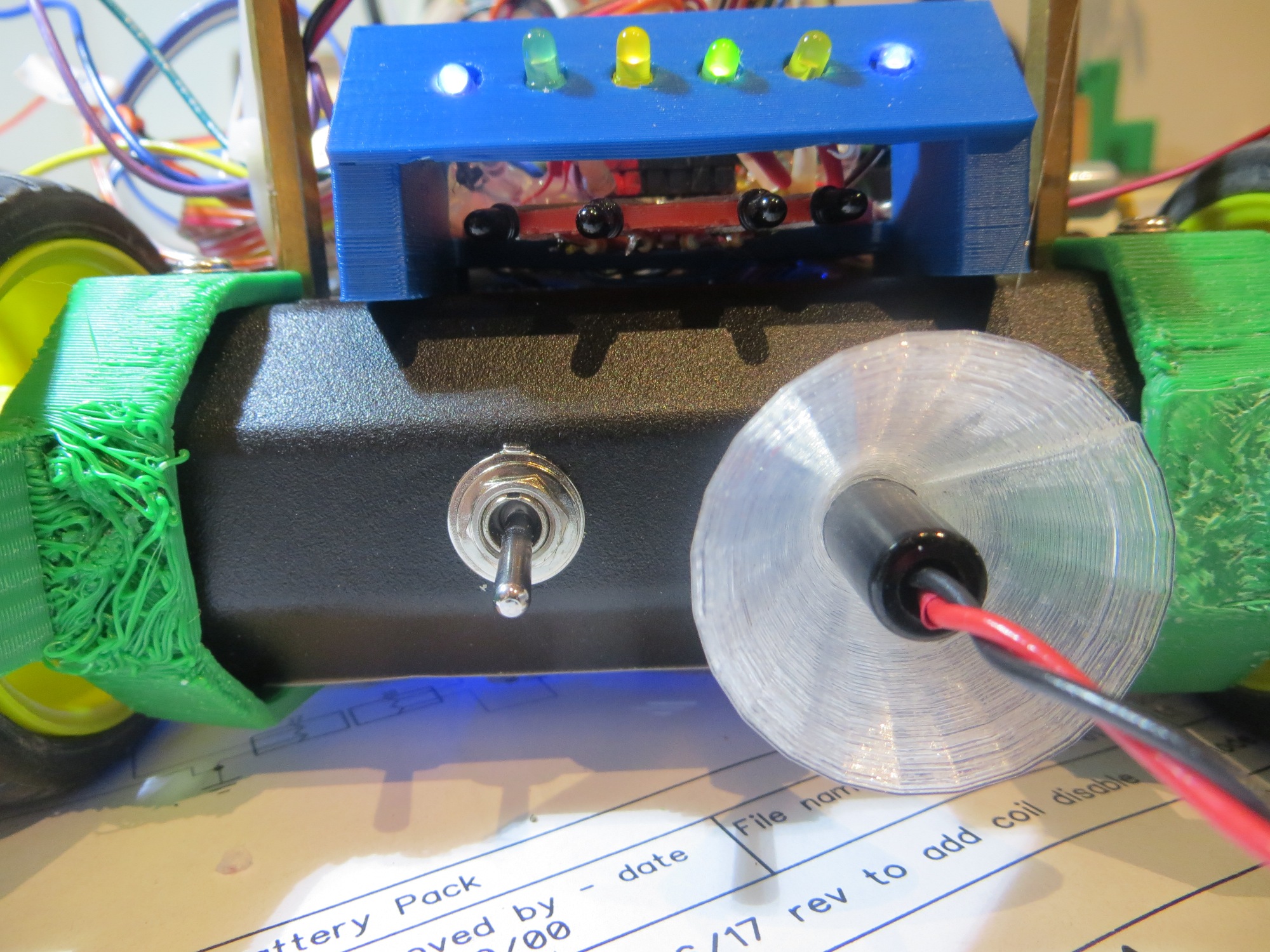
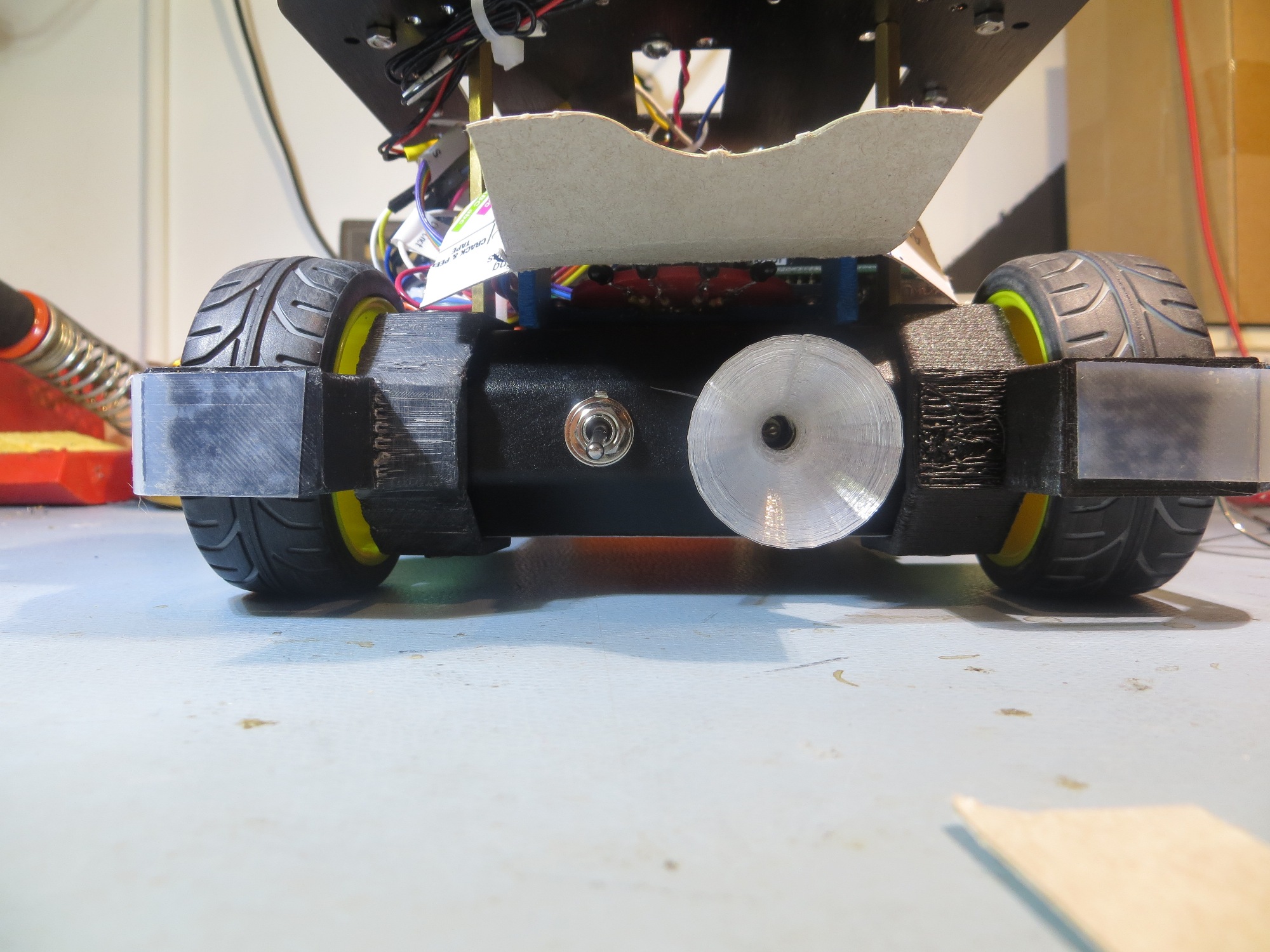
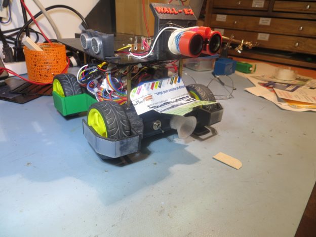
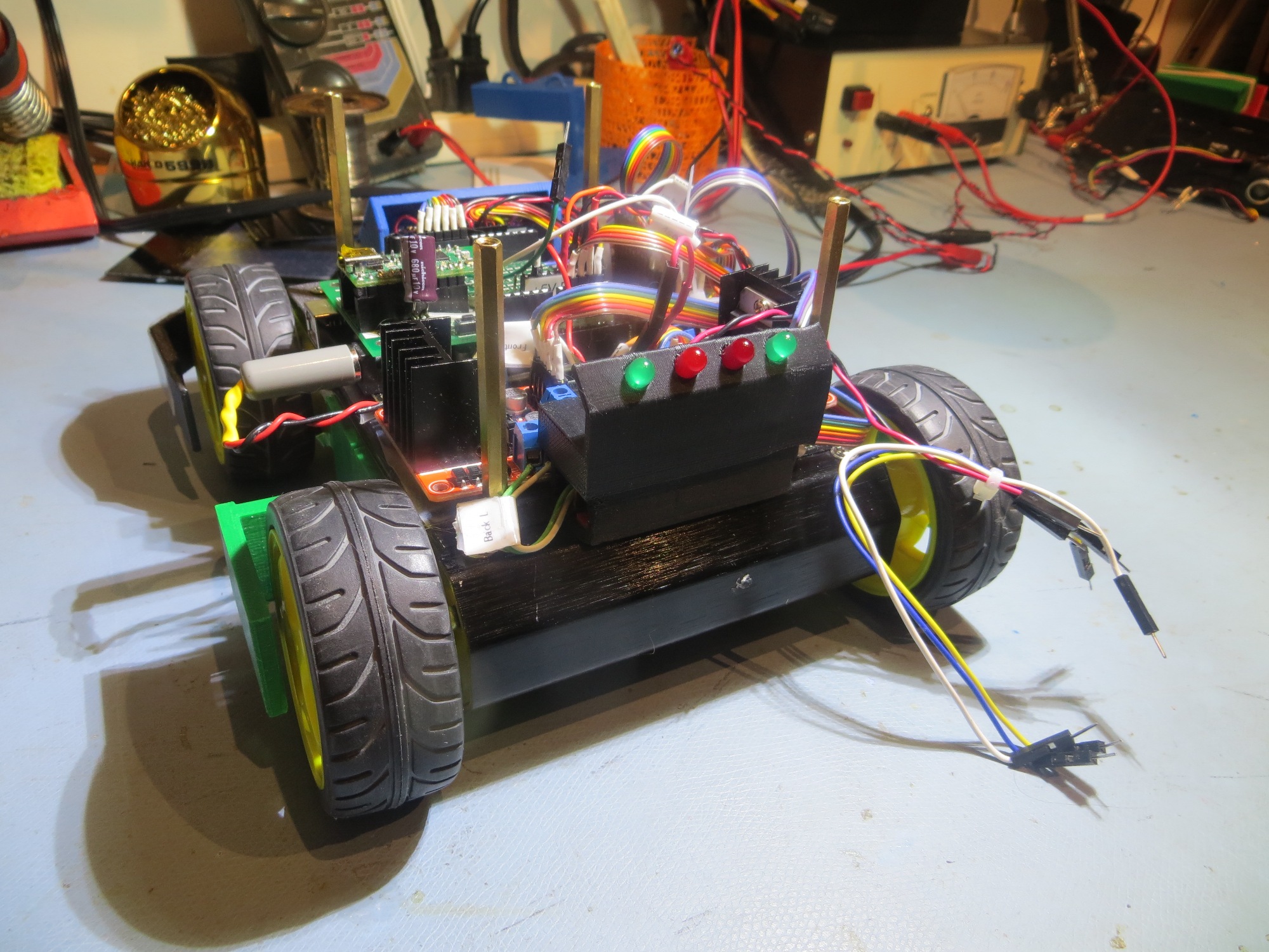
I thought I had solved this problem way back when I first started working with the IR detection/homing idea back in October of last  year.  In that initial post  where I investigated  the  OSEPP IR Light Follower’, I found I had to turn OFF the LED track lights in my lab in order to avoid swamping the detector array.  Over the next month or so this project evolved into a custom designed array of  Oshram SFH309FA-4 phototransistors (see  http://gfpbridge.com/2016/11/ir-light-follower-wall-e2-part-vi/), and as part of this I discovered that the Oshram devices weren’t at all sensitive to the LED track lighting in my lab.  From this I concluded (erroneously as it now turns out!) that I didn’t need a ‘sunshade’ at all, which allowed for a much simpler installation on the robot (see  http://gfpbridge.com/2016/11/ir-light-follower-wall-e2-part-vii/).  Finally, when this module was transferred from the 3-wheel test bed to the Wall-E2 and combined with the charging status display panel, we arrived at the ‘final’ arrangement shown in the following photo

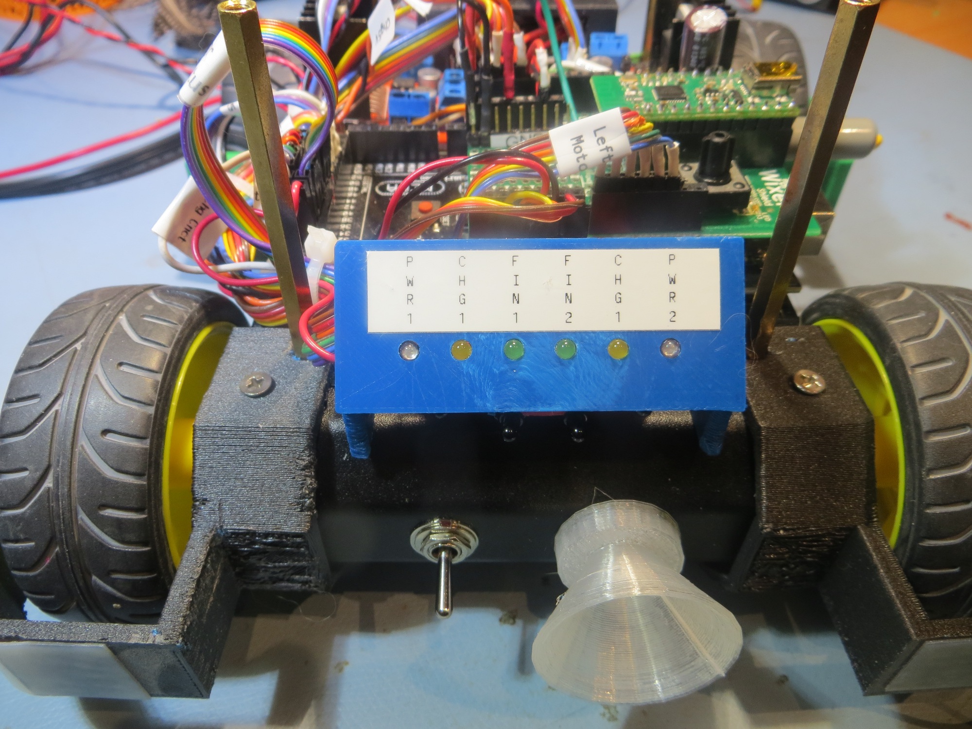
IR detector module (red) shown beneath charging status display panel (blue)

This worked great for all my in-lab IR homing tests with my all-LED overhead track lighting, but as soon as I started testing out in the rest of the house, the overhead incandescent and halogen lamps swamped out the detectors. So, it was back to the drawing board – again :-(.

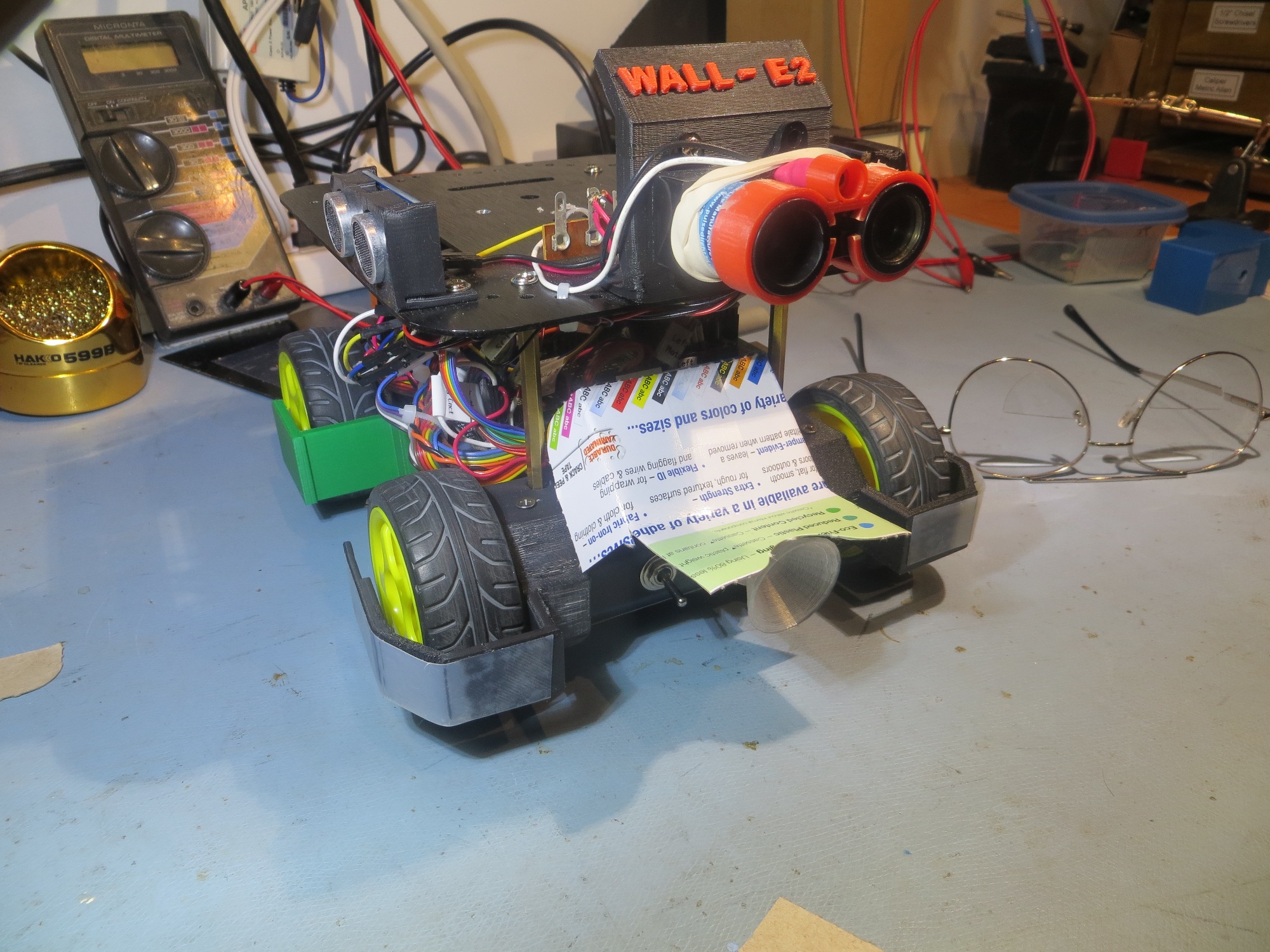
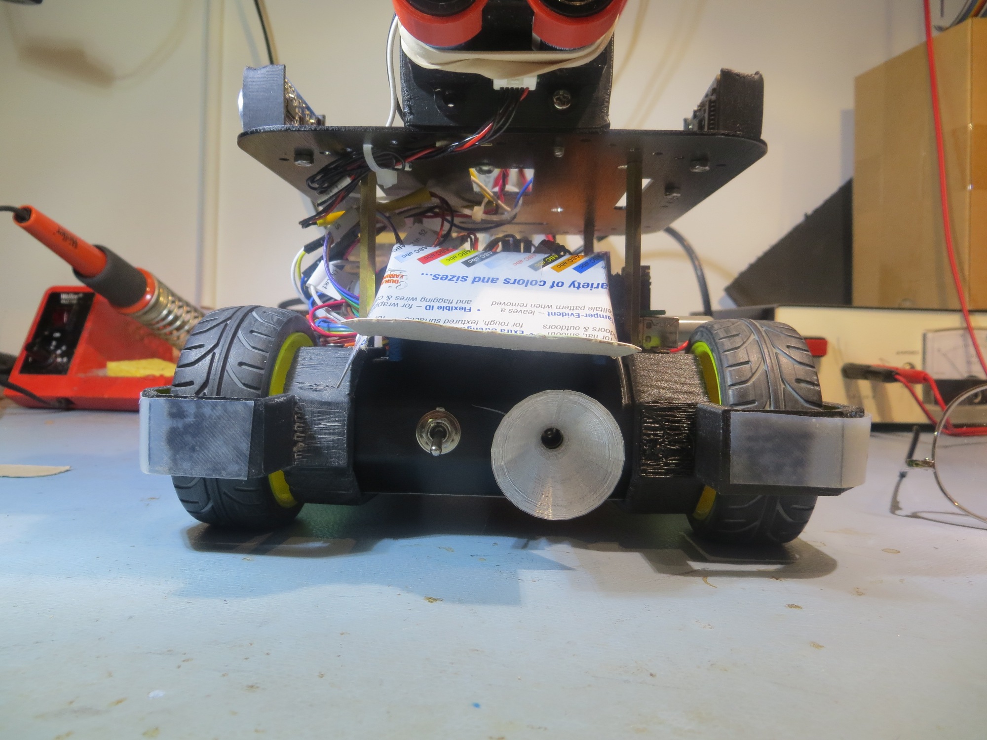
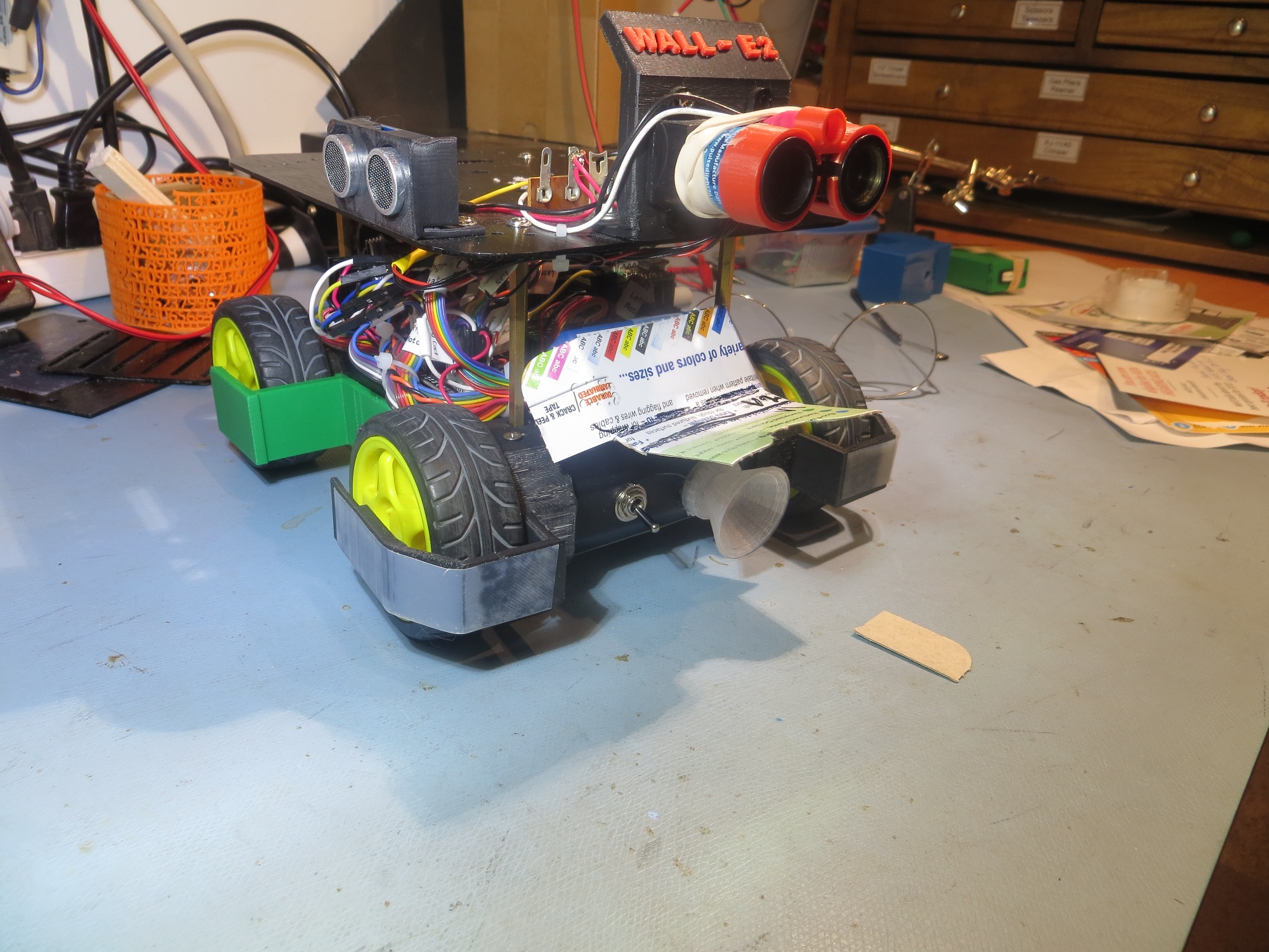
The first thing I did was to confirm that the IR detectors were indeed getting swamped by the overhead lighting, and that it was possible to prevent this by some sort of shielding.  I started with a wrap-around cardboard shield that completely covered the IR detector module, as shown below, and placed the robot on the floor of the entry hallway in a normal ‘wall-following’ position

Sunshade V0. Not very practical, but does set the baseline for the rest of the tests

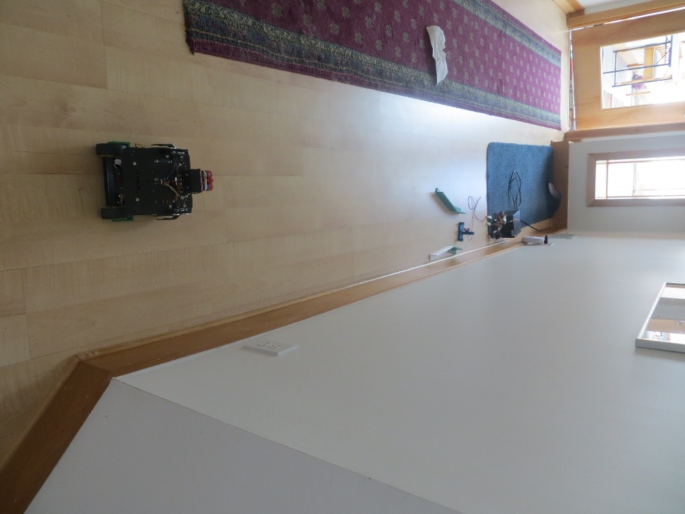
Test position for 07 April 2017 sunshade tests


With this setup, Wall-E2 was pretty much deaf to the overhead lamps, showing no reaction to cycling the lights.  Of course, this configuration would also completely prevent it from detecting the charging station IR beam, but….

Next I modified the above V0 cover to allow a bit more visibility, as shown below:

Sunshade V1 oblique view

Sunshade V1 front view

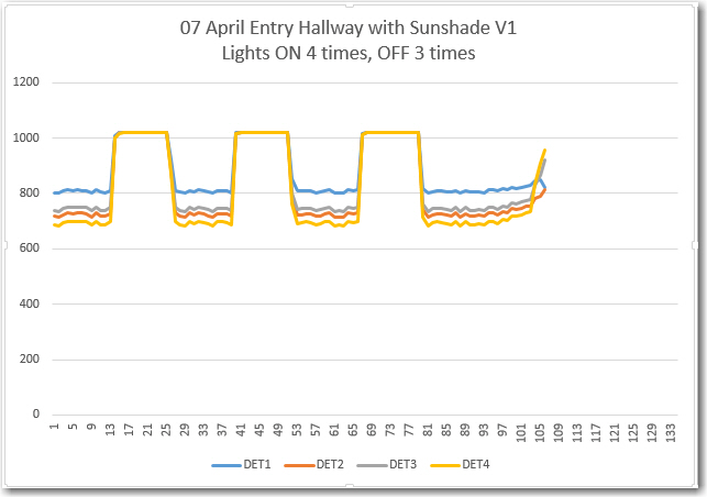
This version is still a bit too restrictive for normal IR beam detection/homing, but was worth a shot for testing purposes.  With this setup, the overhead lighting  is noticeable, as shown below.

Sunshade V1 at sunshade test position. Lights ON four times for 5, 5, 5 and 10 sec

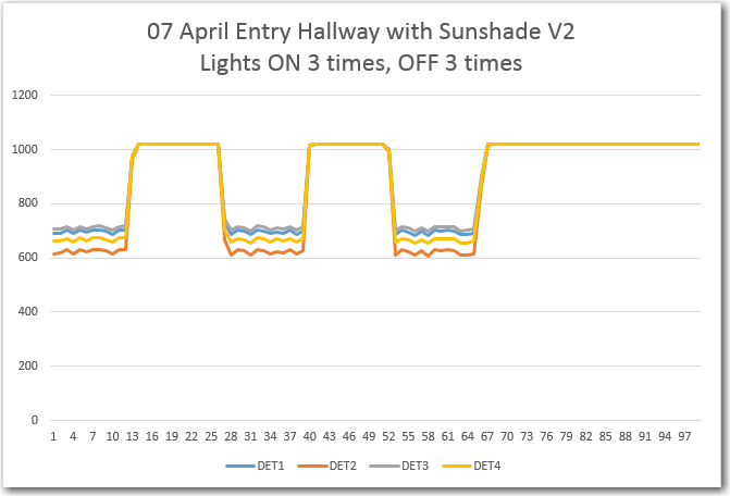
As can be seen from the plot, the V1 sunshade responds to the overhead lamp IR with an average A/D reading about 700 out of 1024.

Next, I modified  the sunshade again so that it would just allow the IR detector module to ‘see’ straight ahead, on the theory that that would be the minimum requirement for successful IR beam detection/homing.  With this setup, the overhead lamp response was stronger, but still not completely overbearing;  the IR detector response to the overhead lights averages A/D values of about 600 out of 1024.

Sunshade V2 oblique view

Sunshade V2 front view.  Note IR detectors visible from directly in front

IR detector response to overhead lamps. ON three times for 5 sec each

When I ran a homing test  with the V2 sunshade in my lab (with LED overheads, not incandescent), the robot homed successfully from about 1 m away, with the following IR detector/homing performance

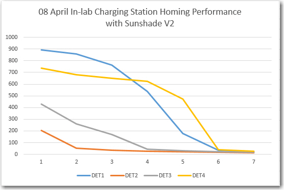
In-lab (LED overhead lighting) charging station homing performance with V2 sunshade

In the above homing test, the IR detector values started out at approximately 900, 200, 450 and 750, respectively.  This means I could set the IR beam detection threshold at, say, 400 and still have a 200-count noise margin in both directions (200 down from the overhead IR flooding value, and 200 up from the typical 1-meter IR beam intensity).  From the movie it is obvious that the minimum IR reading is switching back and forth between at least two detectors, so I think it is safe to say that IR homing would occur even in the presence of a 600 unit noise level, as the 200 or lower reading switched between detectors.

Next, I moved the charging station into the entry hall so I could test IR homing performance with the overhead lights on and off.  My prediction was that Wall-E2 should be able to home successfully in both cases.  For the test, the charging station lead-in rails were oriented in the preferred ’tilted’ orientation, as that should give the best homing performance, as shown in the photos below:

Hallway IR homing test setup

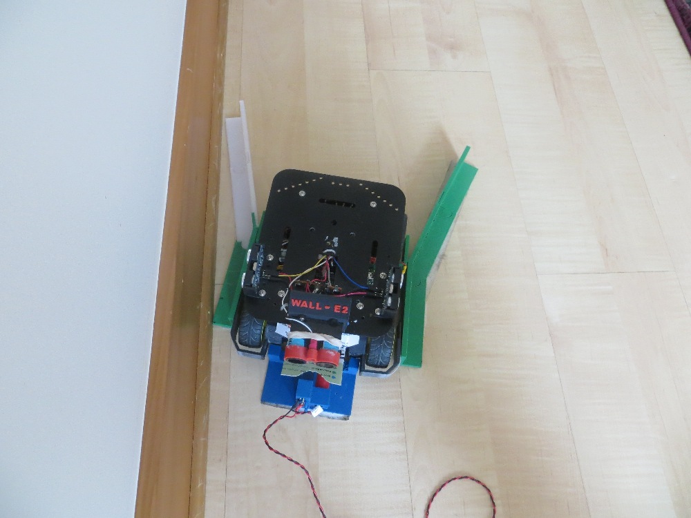
Robot shown in captured position. Note lead-in rail ’tilt’ relative to the wall

I made three runs; Lights ON, lights OFF, and Lights ON, as shown in the three video clips below:


As can be seen in the videos, Wall-E2 successfully homed to the charging station with the overhead lights OFF, but not with them ON – bummer!

So, further testing will be required to determine the particulars of the two failed runs, and what – if anything – can be done about it.

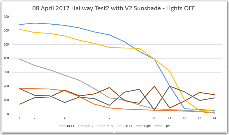
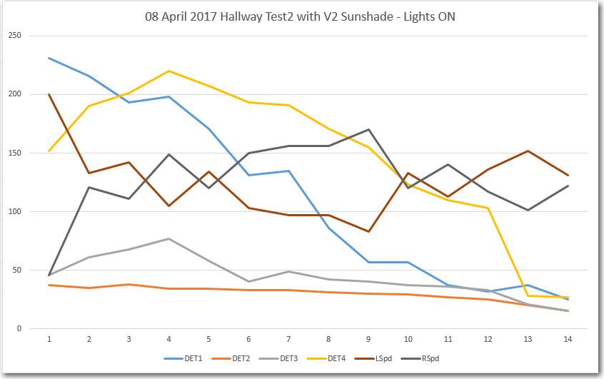
After moving my laptop  out into the hallway so I could capture telemetry from the robot while also filming the runs, and checking everything out, I made two successful IR homing runs – one with the overhead lights ON, and another one with them OFF.  I captured telemetry from both runs, and was clearly able to distinguish between the lights ON and OFF scenarios.  The videos and the telemetry plots are shown below:

08 April 2017 Hallway Test2 with V2 Sunshade – Lights OFF

08 April 2017 Hallway Test2 with V2 Sunshade – Lights ON

From the above plots, the lights ON & OFF conditions are readily recognizable.  In the ‘OFF’ condition, the ‘background noise’ is at about 600-700, and the IR beam is at 100-200.  In the ‘ON’ case, the noise level is higher (lower count), at about 150-250, but the IR beam is lower too – around 50-150.  I guess this makes some sort of sense, as the IR energy from the charging station beam is a separate, additive source relative to the overhead lighting.  Also, both plots show good motor response curves – the left & right motor speeds are obviously being adjusted rapidly in response to IR detector changes.

So, at this point I’m pretty convinced that the V2 sunshade is working, so I plan to print up a permanent version that will (hopefully) simply slide on to the front of the existing charge status display panel.

Stay tuned!

Frank


Charging Station Design, Part XIII – More PID Tuning

Posted 28 March 2017

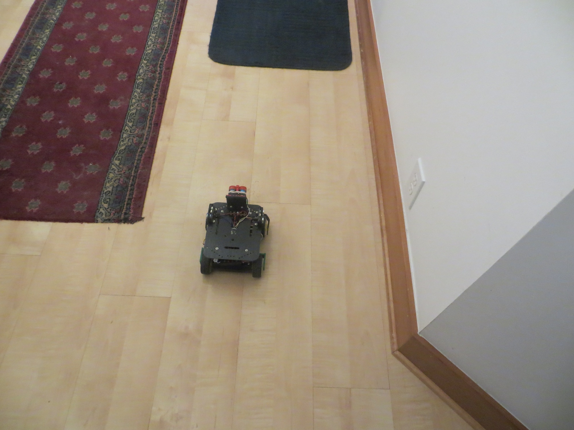
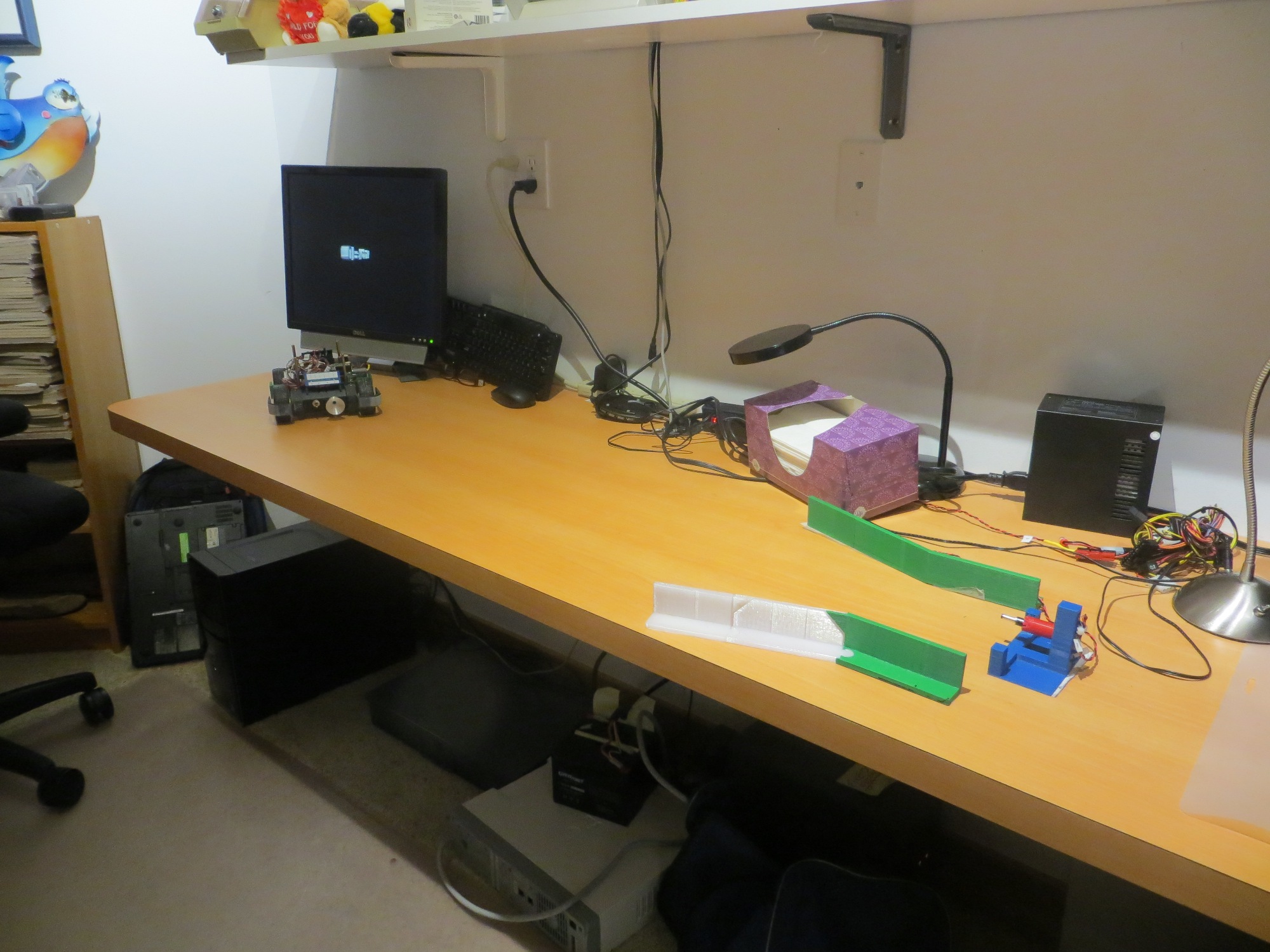
After my cleanup-and-label campaign documented in my last post, I was ready to get back to PID tuning for homing in on the charging station.  When my grandson was here, he pretty much took over my primary work area, so I was forced to move my bench-top testing range to another part of my bench.  This was not quite as convenient for reprogramming the bot, but it did give me a bit more distance between the initial bot position and the IR LED in the charging station, as shown in the following photo

Wall-E2’s new PID test range

I started out by going back to the simplest possible PID setup – namely (p,i,d) = (1,0,0) and ran a series of range tests, as shown in the following video.

As is evident in the video, Wall-E2 has no difficulty homing into the charging station when initially placed near the edge of the bench, but won’t home properly from the other side.  After thinking about this for a bit, I came to the conclusion that the reason for this is that the center of the charging station is physically located near the edge of the bench, so when the bot starts at that edge, it is actually close to the centerline of the charging station, and therefore is almost perfectly lined up at the start. When starting from the other side however, the initial position is not lined up with the charging station centerline and therefore has to make more of a correction to get lined up.  From this I hypothesized that the PID setting of (1,0,0) doesn’t provide enough of a wheel-speed correction to make the required turn.

So, next I tried a PID of (2,0,0), and this worked much better, as shown in the following video

As can be seen from the first run above, the robot is doing a much better job of homing, but unfortunately ran into the left side rail instead of being captured.  This turns out not to be a PID tuning issue, but rather a problem with the IR beacon pattern relative to the lead-in rail arrangement.  The line from the robot’s starting position to the IR LED unfortunately intersected the outside of left lead-in rail instead of the inside.

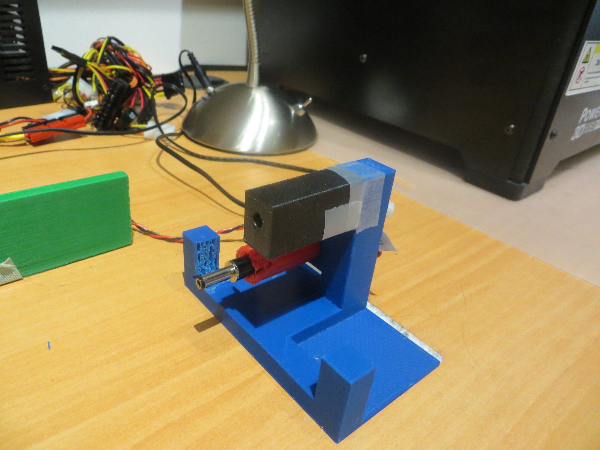
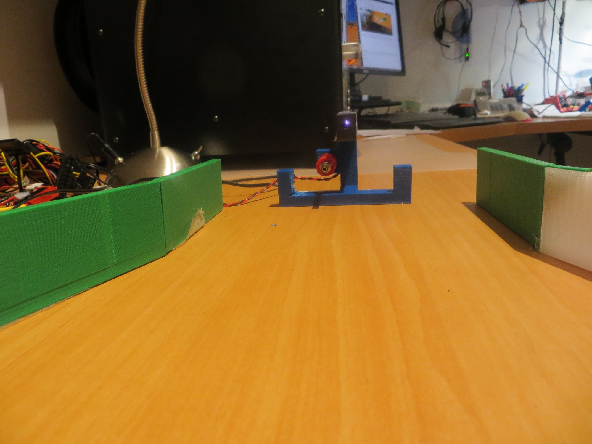
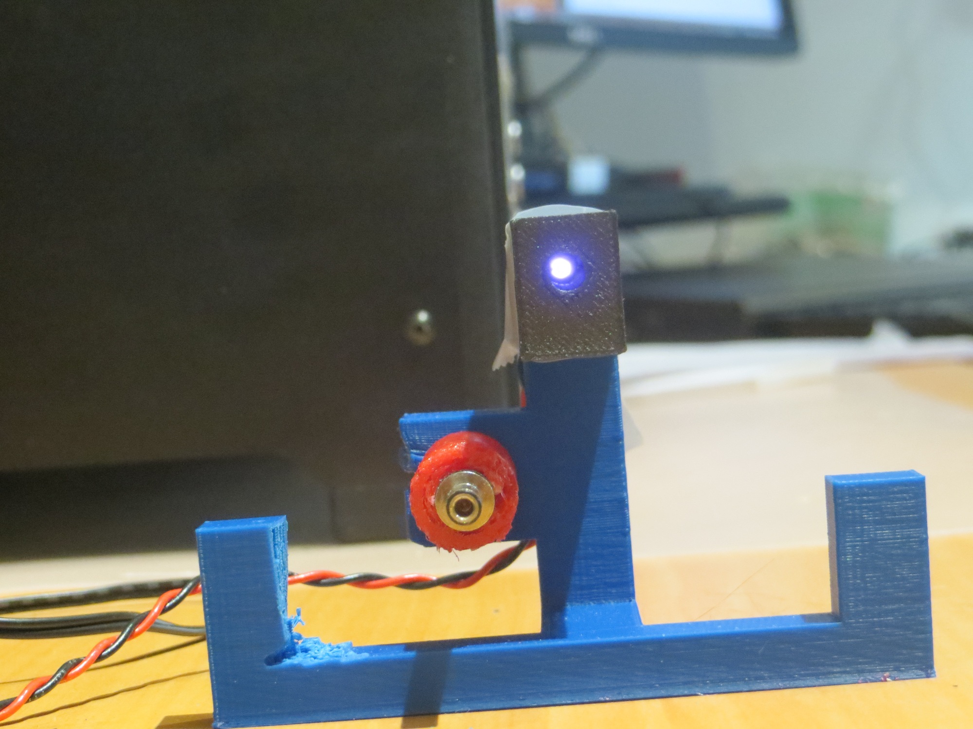
As an experiment to confirm the IR beam pattern hypothesis, I printed up an auxiliary part to restrict (not collimate, as that implies shaping) the beam to a narrower pattern, as shown in the following photos  ( taken with a digital camera with a wavelength range that covers the  IR wavelength being used)

This experiment ‘worked’ in the sense that it showed that the IR beam was no longer visible outside the lead-in rail aperture, but it also made it so narrow that the robot had to be right on the centerline to sense the IR beam at all.  Although this solves the problem of hitting the rail, it would make it very difficult for the robot to ever find the charging station in the first place when approaching at the typical wall-following standoff distance.

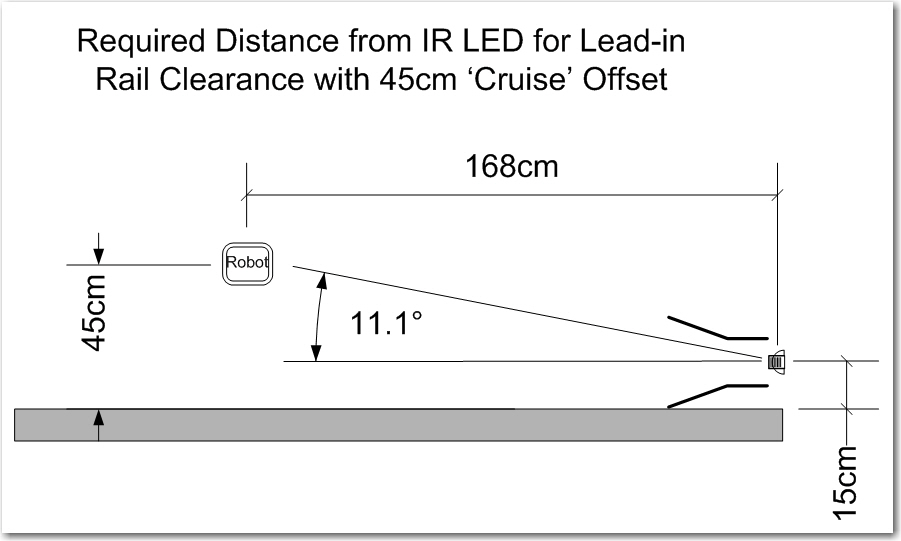
So, although I plan to do a bit more fine-tuning of the PID parameters, it appears that the basic homing problem is solved,  but the challenge now is  getting the robot into a position where it can home in on the IR beam without running into a side rail.  The current wall-following algorithm doesn’t have a set stand-off distance, so the robot may be ‘cruising’ at anywhere from 10-70 cm from the wall being tracked.  Assuming that one lead-in rail is against the wall, the IR led is located about 20 cm out, and the front end of the outside lead-in rail is about 35 cm out.  When the robot is just captured by the outside rail, its centerline is about 16 cm out.  The angle from the IR LED to the center of the robot at this point is about 11-12 º.  So, assuming the robot is wall-following and at some point intersects the IR beam and starts homing, the angle from the robot to the IR LED has to be less than 11-12 º or the robot will not be captured by the lead-in rails.  The situation is shown graphically in the following diagram.

Capture parameters for the robot approaching a charging station

As shown above, if the robot is ‘cruising’ at 45 cm from the wall, then it has to start homing from no less than 1.7 m or so from the charging station in order to get captured by the lead-in rails.  This is  a large, but impossible distance.  The robot can currently home from about 1 m out, so getting out to 1.7 m might be as easy as increasing the IR LED current;   it is  currently running at about 30 mA, and it is rated for 100.

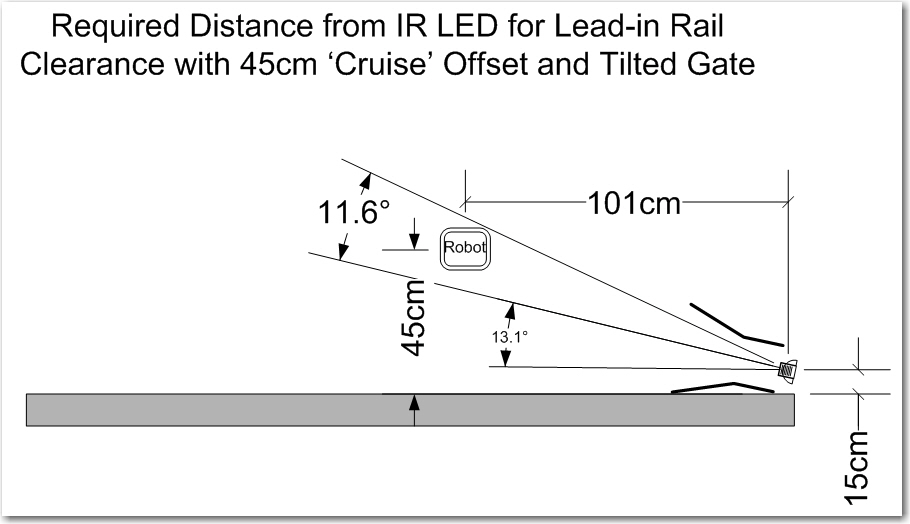
Another possibility is to angle the capture gate out slightly with respect to the wall. There’s no real reason the charging station rails need to be parallel to the wall – it’s just my neat-freak mentality that makes me do things that way.  If I angle it such that the inside lead-in rail touches the wall at both its forward and trailing ends, that will angle the beam out at about 13 º, and move the minimum capture distance in to about 1.0 m, as shown in the following diagram.  1.0 m is just about where the robot is capturing now – yay!!

Tilted gate option. The tilt decreases the minimum required IR beam capture distance from about 1.7m to about 1.0m

So, it appears that tilting the capture gate is the way to go; this doesn’t cost anything but a slight ding in my ‘neat-freak’ index, and should  eliminate or greatly reduce problems with charging station capture failures.

Stay tuned,

Frank


Charging Station Design, Part XII – A Pause to Clean Up

Posted 22 March 2017

This last weekend was devoted to a whirlwind visit by the St. Louis family, which includes my 13-year old, growing-like-a-weed, 3D printing enthusiast grandson.  So, I didn’t get a whole lot of time to work on Wall-E2’s problems, as Danny basically took over my entire lab ;-).  So, now that the horde (can one 13 year-old kid constitute a ‘horde’?) has departed, I can get back to some sort of normalcy and make some progress.

At the end of my last post on this subject, I had concluded that I needed to go back and verify the details of the IR homing hardware and software, as the results I was getting didn’t make sense.  So, I set up some experiments where I could carefully watch the raw output from all 4 IR detectors, and the changes from physically blocking one IR LED at a time.  This experiment convinced me that something was definitely wrong with the hardware; at least one detector appeared to be dead, and it also looked like blocking one detector affected the outputs of more than one – strange!

So, back to the hardware; After dismounting the combined charge status display panel/IR detector module and separating the two, and physically inspecting the IR detector module I  found  a bad solder joint (what – a bad solder joint!?  I  never make bad solder joints! – must have been someone else!) on one of the detector connections to the interface  header.

After repairing the bad solder joint, I carefully worked my way through the cabling maze on Wall-E2 to the microcontroller end of the IR detector cable, to verify proper connection on that end.  The connections looked good, so I did some more testing, only to find that one of the IR detector outputs appeared to be dead – it’s analog reading stayed around 4-500 no matter what I did.  Some more physical inspection revealed the problem – my 4-pin IR detector cable was connected to A2-A6 on the Mega board, but I was reading A1-A5, so the A1 input was essentially ‘open-circuit’ – oops!

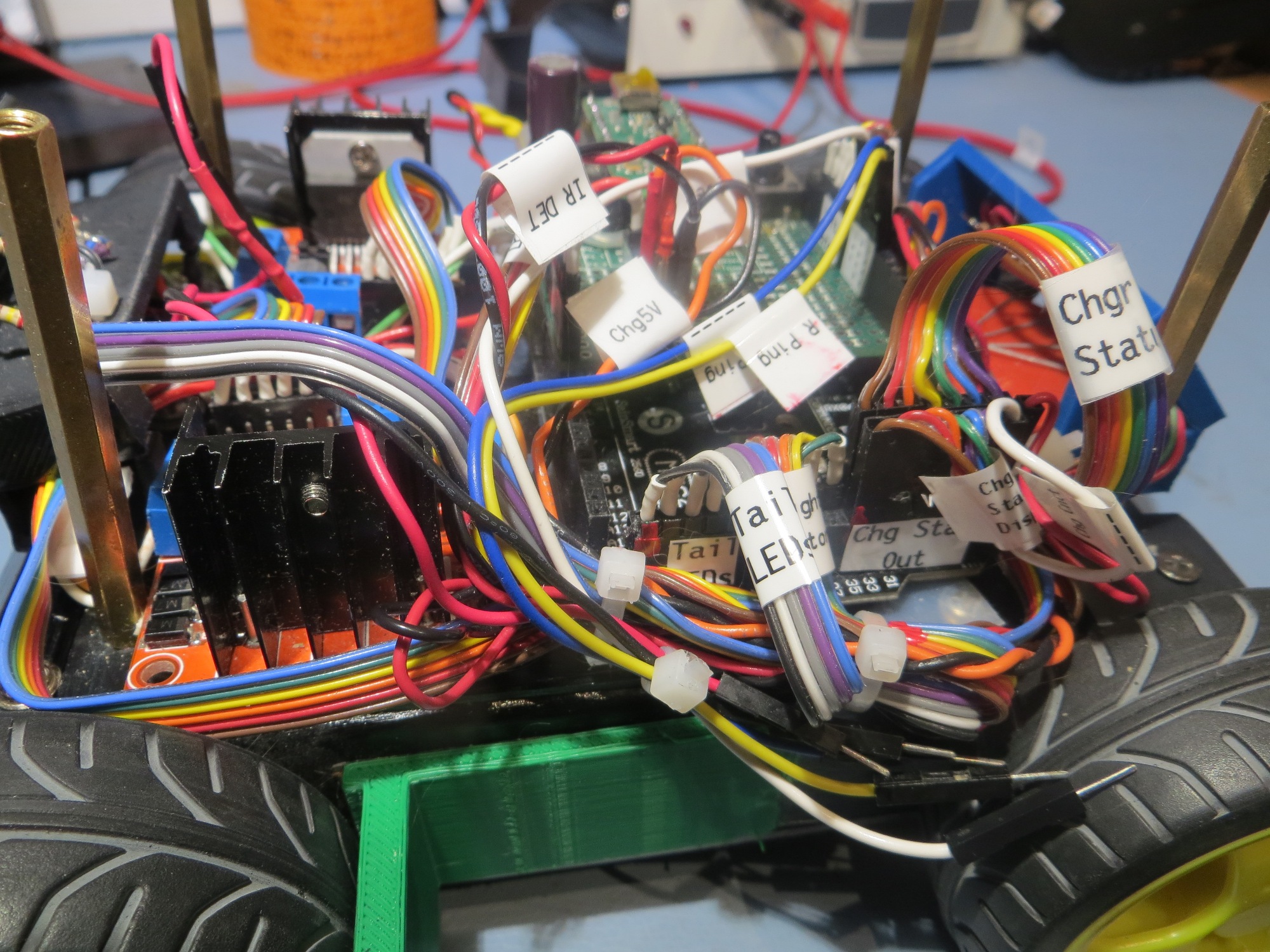
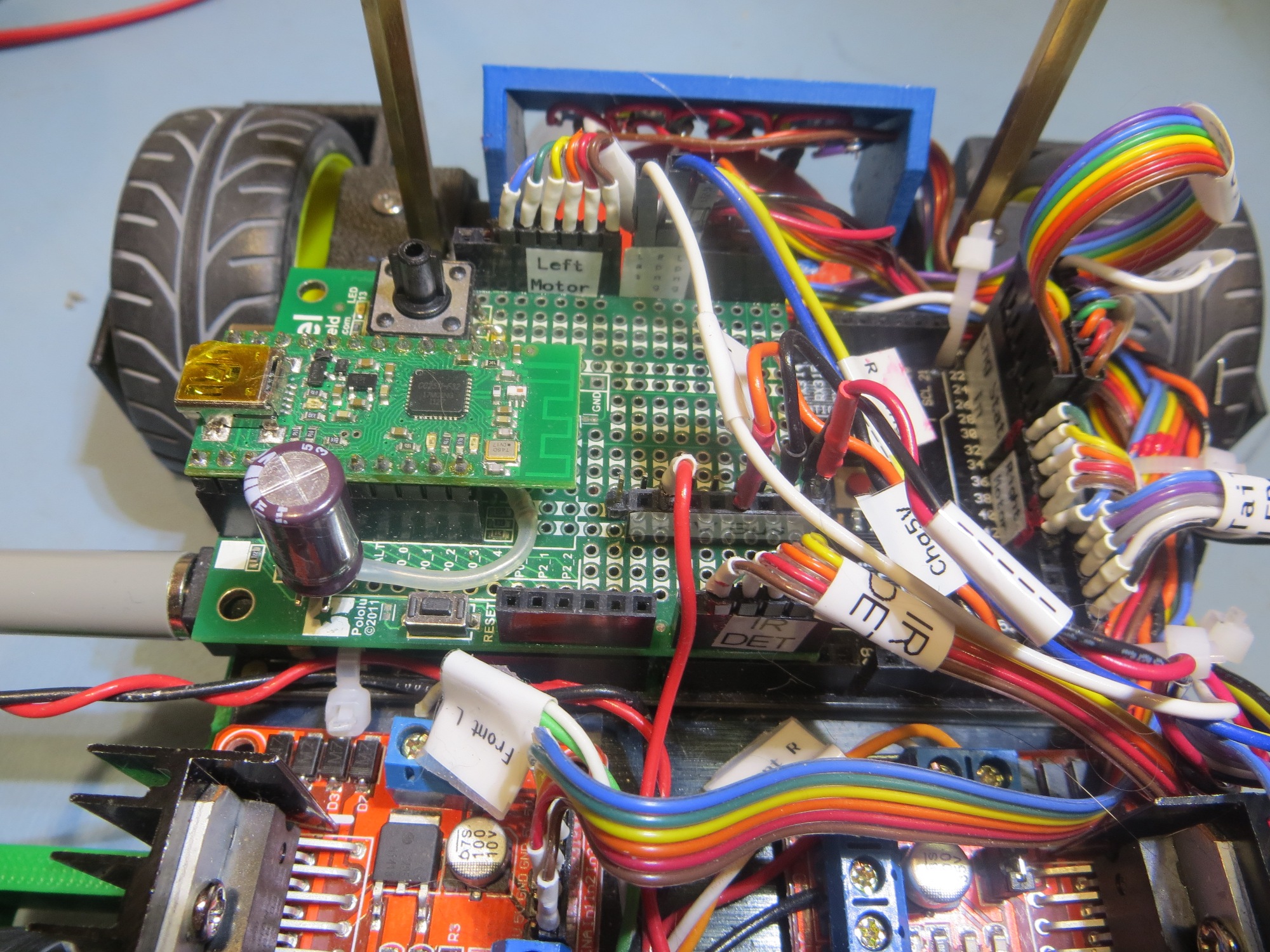
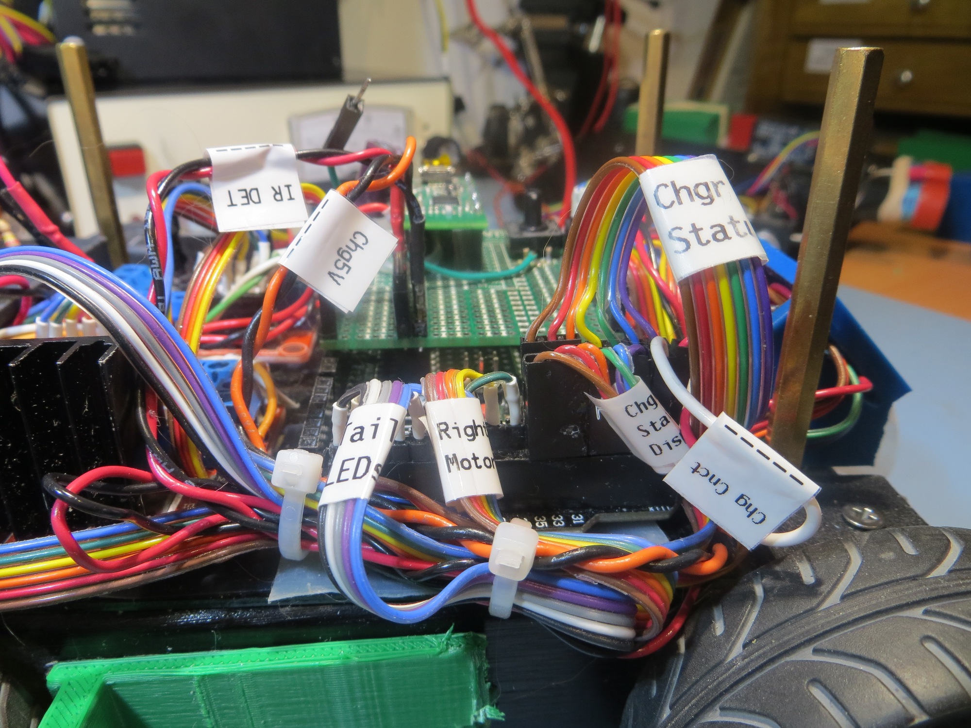
After fixing this booboo, things started to perk up and act a *lot* more normally! ;-).  However, instead of immediately going back to testing mode, I decided that I needed to get serious about labeling and indexing cables (I use red fingernail polish to index one end of each connector to the corresponding microcontroller pin) and connectors  on Wall-E2, so I would have less trouble in the future with the large number of ribbon cables and loose wires now festooning the robot.   Fortunately I have my wonderful Brother P-touch label maker to help me with this task. As an aside, if you are a ‘maker’ hobbyist like myself, a label maker is an absolute godsend, and I can’t recommend the Brother P-touch highly enough.

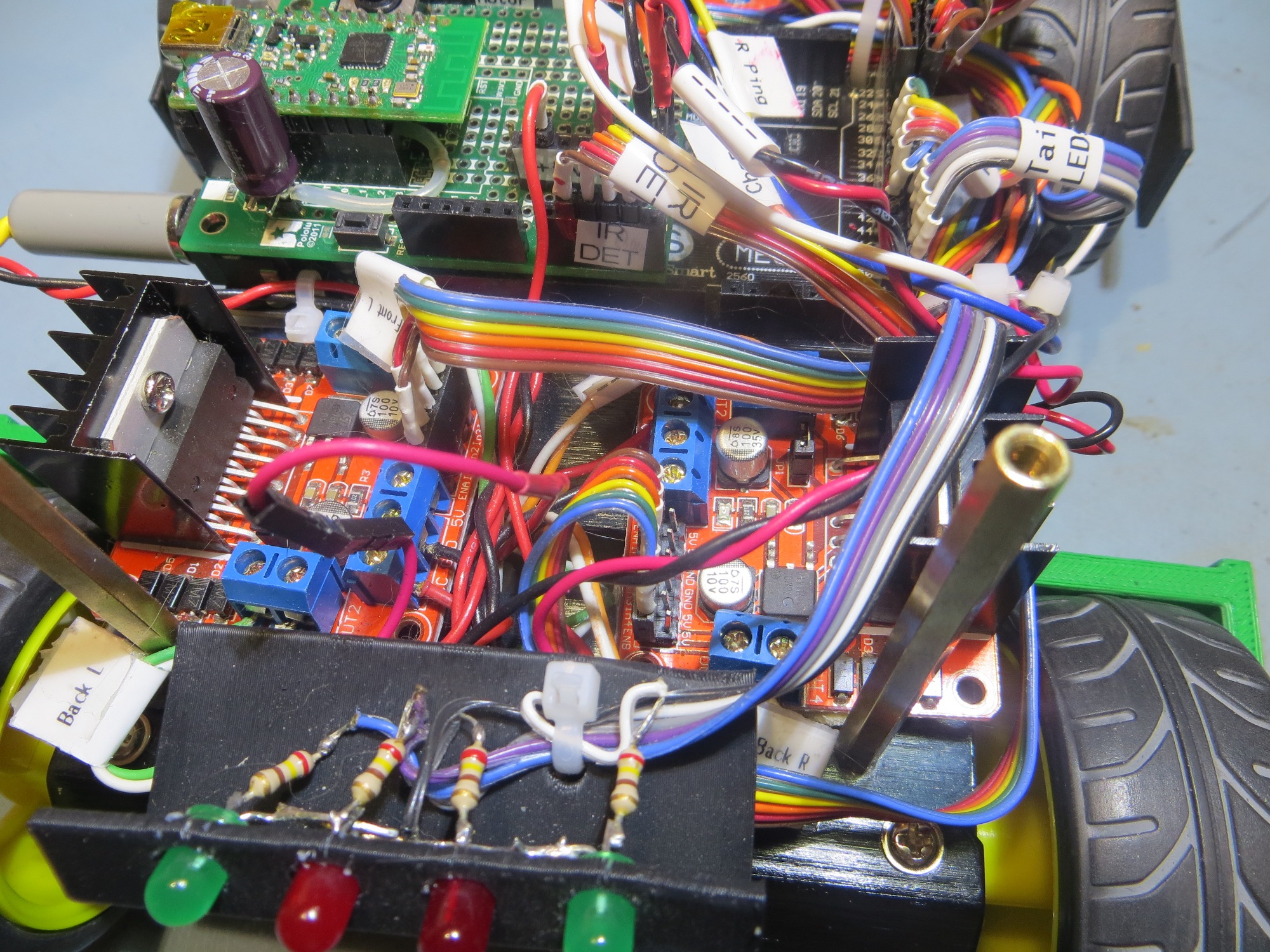
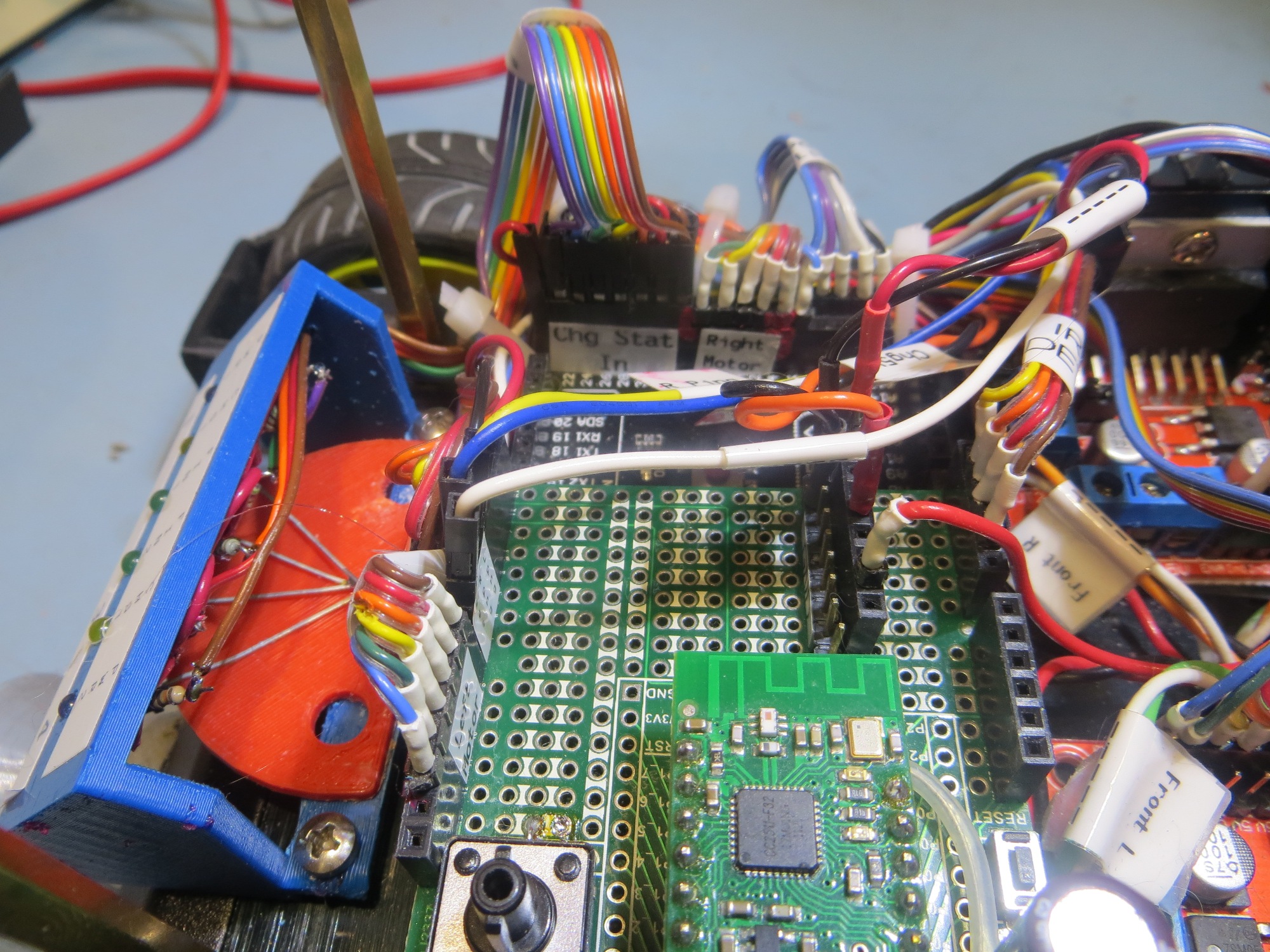
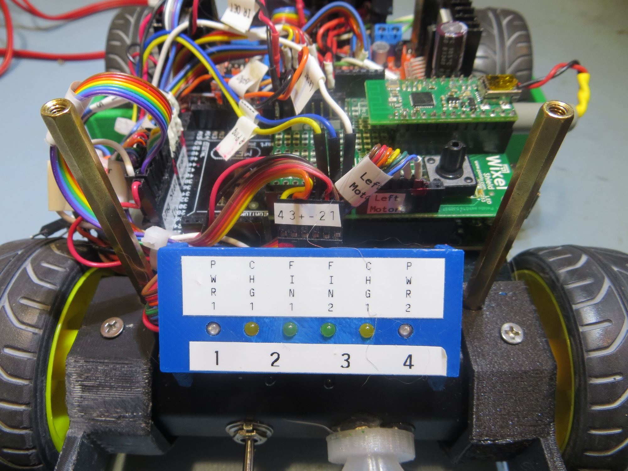
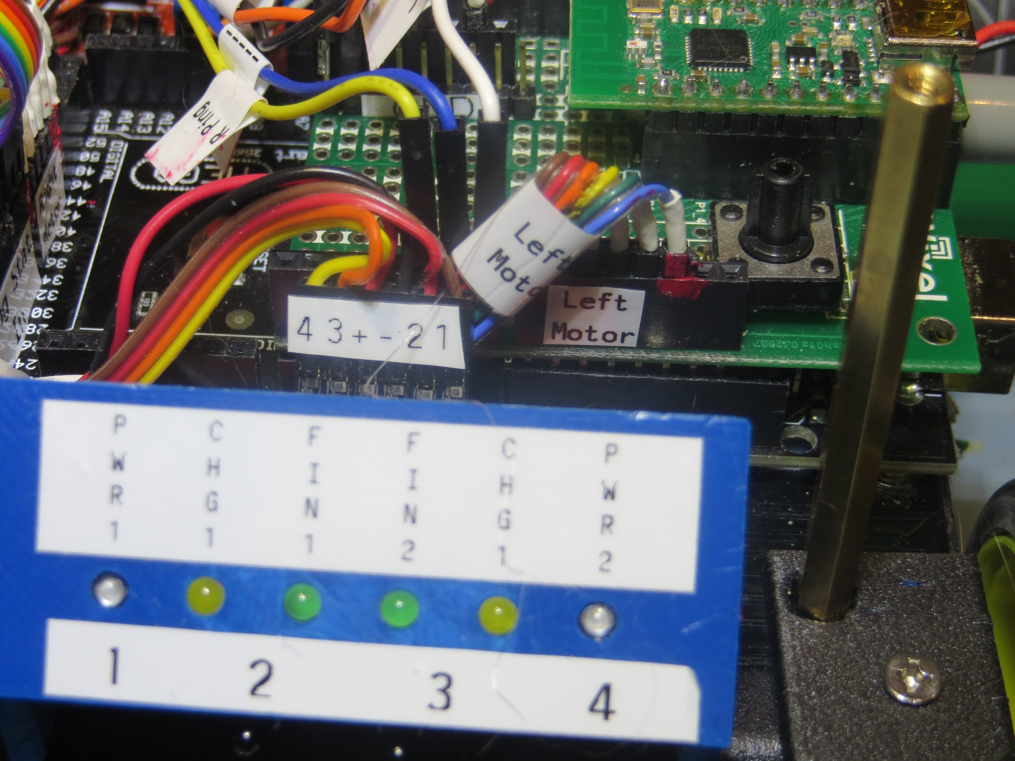
After my labeling and cleanup campaign, Wall-E2 is  a lot more self-documenting, as shown in the following photos

Charging Station Design, Part XI – PID Tuning

Posted 14 March 2017

As I was doing the IR homing tests described in my last post, I noted that Wall-E2 wasn’t all that great at homing; in particular it missed the opening in the lead-in rails on several occasions, instead hanging up on one side or another.  This was a bit mystifying to me, as I thought I had the homing code working very well with my old 3-wheel robot (see ‘IR Light Follower for Wall-E2, Part X – More PID Tuning‘).  At the time, I decided to use one of my best scientific research tools and simply ignore the problem, hoping it would either go away, or my subconscious mind (by far smarter than my conscious one!) would figure it out in the shower or while drifting off to sleep.

And, in fact, last night while drifting off to sleep, I remembered that the PID tuning for the 3-wheel robot had to take into account the fact that  even small  differences in drive wheel speeds get magnified by the free-castering front wheel.  Wall-E2, with its all-wheel drive  behaves entirely differently, and since small wheel speed differences don’t get amplified into big directional changes, the PID tuning parameters appropriate for the 3-wheel version are too passive for the 4-wheel one.

So, I went back to the drawing board (again!) for PID tuning for the 4WD Wall-E2, starting with the current 3-wheel parameters as the ‘too passive’ baseline.  From my previous article, the final PID parameters were P = 0.1, I = 10, D = 0.2, with the input scaled by 1, 5, or 10 depending on IR beam signal strength.  My initial thought is that the 4WD robot needs a lot more ‘D’ (differential) to increase its turn rate with respect to IR beam heading changes, so I tried a couple of runs with the D value increased from 0.2 to 2 (factor of 10 increase).  As the following video shows, this did seems to increase Wall-E2’s agility somewhat, but still not enough to overcome even minor initial heading offsets, especially to the left.

After some more testing with different values of P,I,D, I began to wonder if I might be having problems with the basic IR detection hardware and homing software, independent of the PID tuning issue.  When I did the previous PID study, I also captured the raw detector data, which allowed me to determine how the PID tuning and the basic detection hardware/software were interacting.  I may have to go back and do that again with the 4WD setup

Stay tuned,

Frank


Charging Station Design, Part X

Posted 11 March 2017

The last few days have been spent partially implementing the software structure and state design described in my ‘Wall-E2 Operating Mode Review‘ of 06 March.  Up to this point, the only thing Wall-E2 knew how to do was wall-following, but there were (and still are) a number of ‘sub-modes’ associated with wall-following.  Now all of this code has to be grouped into the  ‘Wall-Following’ state/function under the main program, and the new ‘Charging’ and ‘IR Homing’ state/functions added.

For purposes of testing, I decided to basically comment out all the wall-following code and concentrate on the IR Homing and Charge modes.  To do this, I added the new operating mode determination and top-level case switching code at the top of ‘loop()’, and left the MODE_WALLFOLLOW: case un-implemented.  the MODE_CHARGING code is all new, but the MODE_IRHOMING code was copied from my previous work with the 3-wheel robot last November.

After getting most of the MODE_CHARGING and MODE_IRHOMING code implemented, I ran some bench tests to see how well things work.  After finding and fixing a number of typos, logic errors, and downright goofs, I was able to video a successful IR home to charge, followed by a charge-completion  disconnect (instead of waiting for a full charge termination, I tied execution to manual charge plug disconnect).  Here is the video


A couple of side notes from the above video

  • It is evident that the IR homing with PID works very well, to the point where the lead-in side rails almost aren’t needed (but only ‘almost’, I fear)
  • The fixed charging station fixture isn’t quite high enough.  In order to more accurately line up with the center of the charging port, I had to raise the fixture by about 5mm
  • The disconnect routine backs up far enough, but doesn’t quite make a complete 90 º turn.  I should be able to tweak the turn duration a bit to make that happen.

So, at this point, I think I have most of the new parts of the operating system working, although some parts are hard to test due to the long charge times.  Here’s what I think remains to be done:

  • Reconnect and test the LIDAR and ping sensor hardware; this will be required to test wall-following and the charge station avoidance sub-mode
  • Reprint the charging station fixture with 5mm more height
  • Set up the full lead-in rail arrangement and confirm proper homing/engagement, along with proper dis-engagement, and proper avoidance when the battery isn’t low.
  • re-implement and test the wall-following code in the new structure, as MODE_WALLFOLLOW.  This  should be just a bunch of cut-and-paste operations.
  • test the various ‘normal’ state transitions; wall-follow to IR homing to charge monitoring to wall-following
  • test the wall-follow to IR homing to charge station avoidance transition.
  • fully test the end-of-charge scenario.

12 March Update

I reconnected the LIDAR and ping sensor hardware, and confirmed (not without some wailing and gnashing of teeth!) proper operation.

I reprinted the charging station fixture with a 5mm pedestal, and transferred the LED/charging plug from the old fixture to the new one.

Set up the lead-in rails on my benchtop so that I could test both the ‘hungry’ and ‘not hungry’ IR homing scenarios.

Tested the ‘not hungry’ scenario by setting the ‘full’ threshold back down to 7.4V (50% charge, per http://batteryuniversity.com/learn/article/lithium_based_batteries).  The following video shows one of the test runs:


13 March Update:

After a bunch of software and hardware bugfixes, I think I finally have the ‘home to charge’ scenario working, as shown in the following video clip and edited telemetry capture:

The significant parts of the video are:

  • The POST test  in the first few seconds
  • The successful IR homing operation
  • The successful charger plug engagement.  When the robot senses the charger plug, it commands the motors to stop.
  • Just after the charger plug engages, the charger’s battery relay is enabled, which disables power to the motors (note the red motor controller power LED goes OFF).
  • For this test, the BATT_CHG_TIMEOUT_SEC parameter was set to 10 seconds.  Rather than wait the entire 10sec, all but the first few and last few seconds were clipped.  Note that after the 10sec timeout, the robot disables the charger relay which re-applies motor power to the robot (note the red motor controller LED is re-enabled), and the robot backs off the charger plug.
  • The robot now backs completely clear of the lead-in rails, and turns away from the nearest wall before going back to wall-following mode.

I have also posted an edited version of the telemetry captured during this test.  As you can see, the robot transitions to IR homing mode, successfully homes on and engages with the charging plug, monitors the charging process, an then executes the ‘ExecDisconManeuver()’ to disengage from the charger and back out of the charging station area.

Loader Loading...
EAD Logo Taking too long?

Reload Reload document
| Open Open in new tab

Download


Stay tuned,

Frank


Wall-E2 Operating Mode Review

Posted 06 March 2017

At this point in the 4WD robot’s development, I think it might be time to review all of  Wall-E2’s different operating modes, and  what external sensor conditions determine which operating mode is active.  Previous to this point, the robot had only one operating mode – the ‘Wall-Following’ mode.  Now that the new battery pack has been added, along with the new capability for homing in on an IR beam to connect to a charging station has been added, the robot operating system must be enhanced to manage the additional operating modes.

Operating Modes/States:

  • Wall-Following:  This is the ‘normal’ operating mode, active when nothing else is going on (no IR beam present, no charging voltage present)
  • IR Beam Homing: Occurs when an IR beam is detected.  In this mode, a PID controller determines wheel speeds in an attempt to home in on the IR source.  This mode has two distinct sub-modes, depending on the battery state of charge.  if the battery is relatively full, then the front obstacle avoidance distance is  increased such that the obstacle avoidance turn will occur before the robot gets captured by the lead-in side rails.  Otherwise, the obstacle avoidance distance is disabled entirely, allowing the robot to be captured and the charging connection to be made
  • Charging:  Occurs when the robot is connected to the charger.  In this mode, the charging status lines are monitored to detect end-of-charge (EOC).  When EOC is detected, the robot backs straight out of the lead-in rail area, and then turns 90 º away from the nearest wall and transitions to wall-following mode.

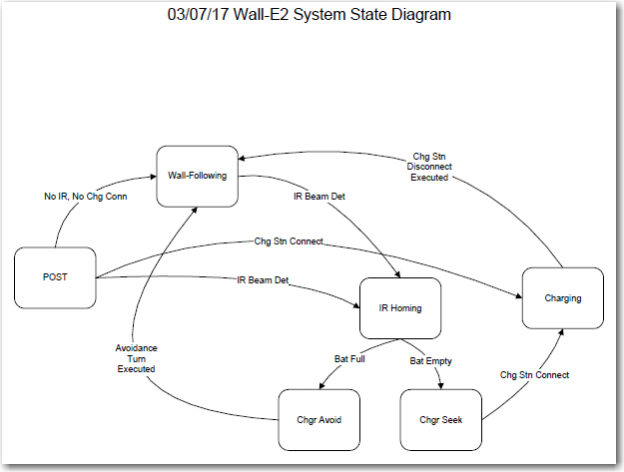
Here is a draft state-transition diagram for the system

Loader Loading...
EAD Logo Taking too long?

Reload Reload document
| Open Open in new tab

Download

As can be seen from the diagram, the system starts out in the POST (Power On Self Test) state, and transitions to one of the other states depending on sensor input.

  • If no IR beam is detectable, and the charging station is not connected, then the system transitions to the normal ‘Wall-Following’ state.  The wall-following state continues until either an IR beam is detected, or  a physical connection to a  charging station is detected.  The normal exit condition from the wall-following state is via detection of an IR beam, which causes transition to the ‘IR Homing’ state.
  • In the IR Homing state, there are two possible behaviors; if the battery is more than 3/4 full (not quite sure how I’m going to define that, but…), then the robot will actively avoid the charging station by performing an obstacle avoidance 90 º degree turn at a  front distance larger than the extent of the charging station lead-in gate, and transitioning back to the ‘Wall-Following’ state.  If the battery is less than 3/4 full and a charge is desired, then the robot will continue to home in on the IR beam until a physical connection to the charging station is detected, whereupon the system transitions to the ‘Charging’ state.
  • In the Charging state, the system monitors the charging status signals, waiting for both ‘Fin1’ and ‘Fin2’ signals to become TRUE.  When this happens, the robot  backs out of the charging station lead-in gate area, executes a 90 º turn away from the nearest wall, and transitions back to the ‘Wall-Following’ state.

Here is a first cut at a system software structure chart that incorporates the above modes/states

Loader Loading...
EAD Logo Taking too long?

Reload Reload document
| Open Open in new tab

Download

Wall-E2 System Documentation

Posted 27 February 2017

In a previous post I described a charging status display panel that was co-mounted with the front-mounted IR detector assembly. The status panel showed charging power, ‘on-charge’, and ‘Finished charging’ status lights for both chargers.  This is what I was after with this panel, but I ran into some problems that led me to reconsider this whole arrangement.

  • In the original design, the status signal lines from the charger module ran directly to the display panel, but not to the controller.  The controller has to be ‘in the loop’ for charging status, as it has to decide when to disconnect from charging  power and from the charging station.  I added lines to piggyback the signals to the controller, but this became ugly very quickly
  • The physical panel I came up with worked OK, but was more than a little un-elegant; the LED mounting holes were  way too big, so the physical alignment of the LEDs was very poor.

So, I decided to re-do this entire physical module and wiring layout.  When considering the wiring, I had a couple of alternatives.

  • I could essentially re-do the original wiring plan – i.e. run a cable  from the charging module to the display panel, and then tap off this cable to the controller.  This is messy, but only uses 6 controller pins.
  • I could run the cable from the charging module directly to the controller, and then run a separate cable from the controller to the display panel.  This uses 12 controller pins, but has the advantage of being much neater,  and  considerably simplifies the display panel wiring.

Considering these two alternatives, the natural question becomes ‘can I afford to waste 6 controller pins just for neatness/elegance?’  To answer this question I decided to do an audit of the current Mega pin usage.  I created a nice little Excel spreadsheet listing all the available Mega pins, their nominal functions (analog/digital/serial) and their current assignments, as shown below:

Loader Loading...
EAD Logo Taking too long?

Reload Reload document
| Open Open in new tab

Download

As can be seen from the document, there are  lots of unused pins available, so using an additional 6 pins for neatness/elegance seems like a pretty easy trade-off.  So, my plan is to run the charger module status cable to controller pins 34, 32, 30, 28, 26, 24 & 22 (Pwr1, Chg1, Fin1, Coil En, Fin2, Chg2, Pwr2), and a corresponding LED drive  cable from controller pins 35, 33, 31, 29, 27  &  25

04 March 2017 Update

After adding all the status signal input and status LED output lines associated with the Charger Module  and moving the ‘Charger Connected’ line from pin 2 to pin 23 to be in the same group with all the other charger-associated lines, I updated the pin assignment spreadsheet as shown in the following PDF document:

Loader Loading...
EAD Logo Taking too long?

Reload Reload document
| Open Open in new tab

Download

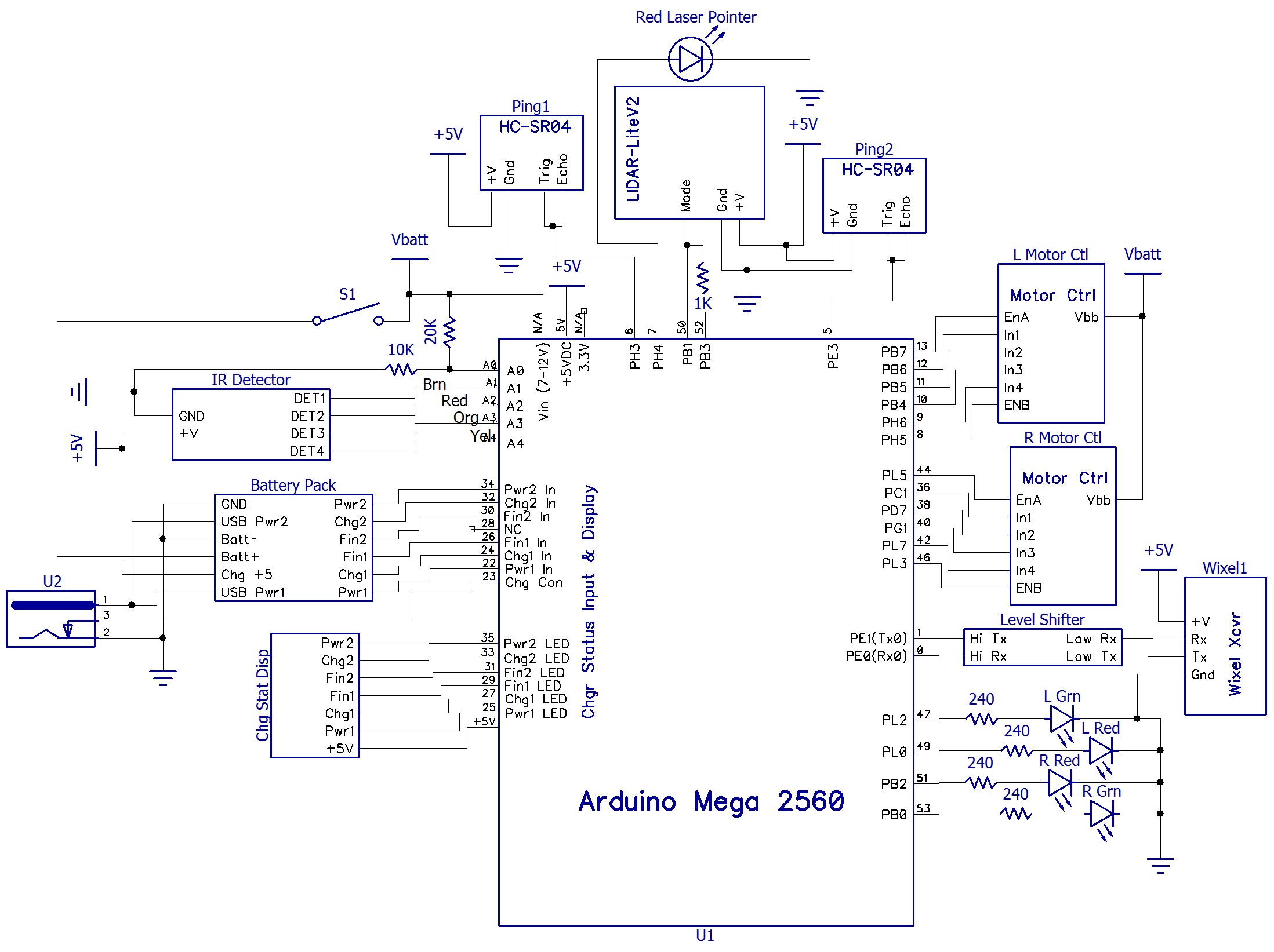
The  next challenge was to reorganize and update the system schematic to reflect all the new inputs, outputs, and function blocks.  The complete system schematic is shown below:


4WD Robot System Schematic with pin assignments as of 05 March 2017

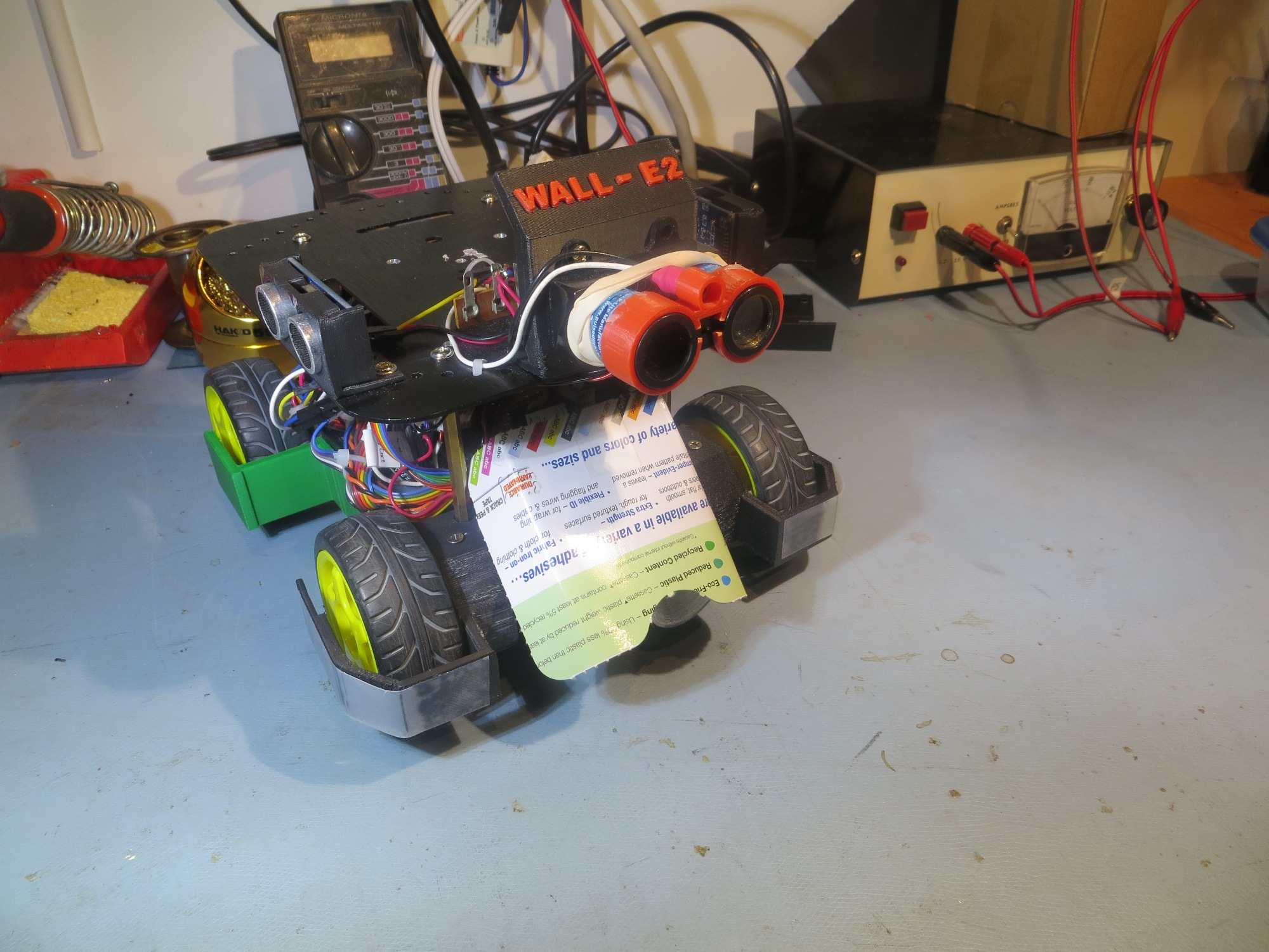
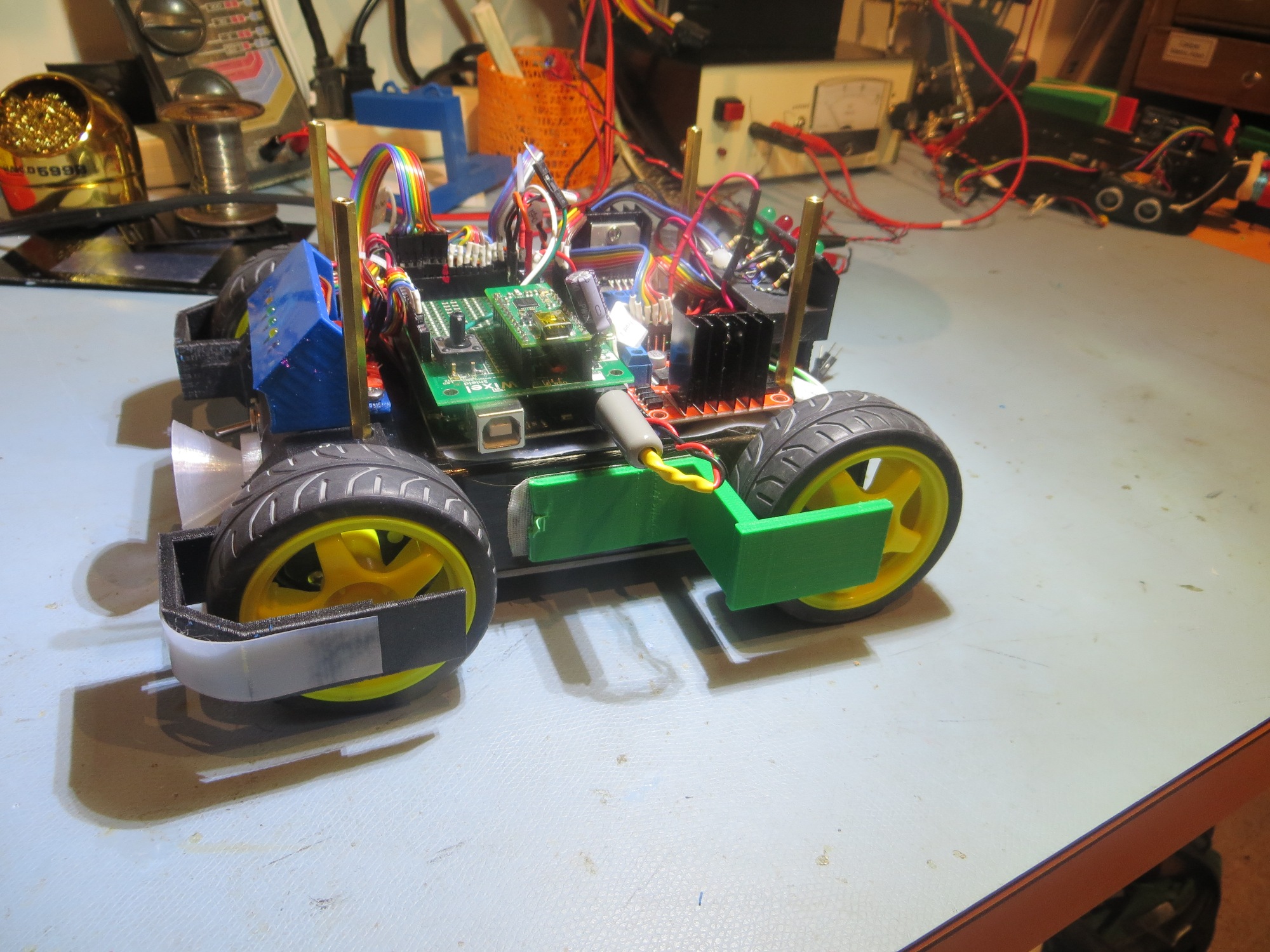
For completeness, I have included front, rear and both side views of Wall-E2 in its current state of construction.  The new battery pack and associated charging electronics has been fully integrated into the internal volume, and all the charging-station related modules/electronics have also been mounted.   The only thing missing physically at this point is the second deck with its two sonar ping sensors, the LIDAR forward distance sensor, and the forward red laser pointer

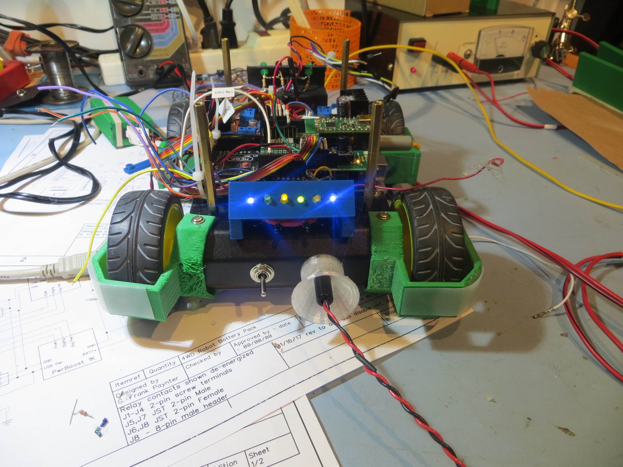
Front view showing charger jack coupler and new charge status display

Left-side view. Nothing much has changed in this view

Rear view showing ‘taillight’ assembly. Loose cabling is for 2nd deck ping sensors

Right-side view showing some of the new cable bundles

Frank


Charging Station Design, Part IX

Posted 20 February 2017

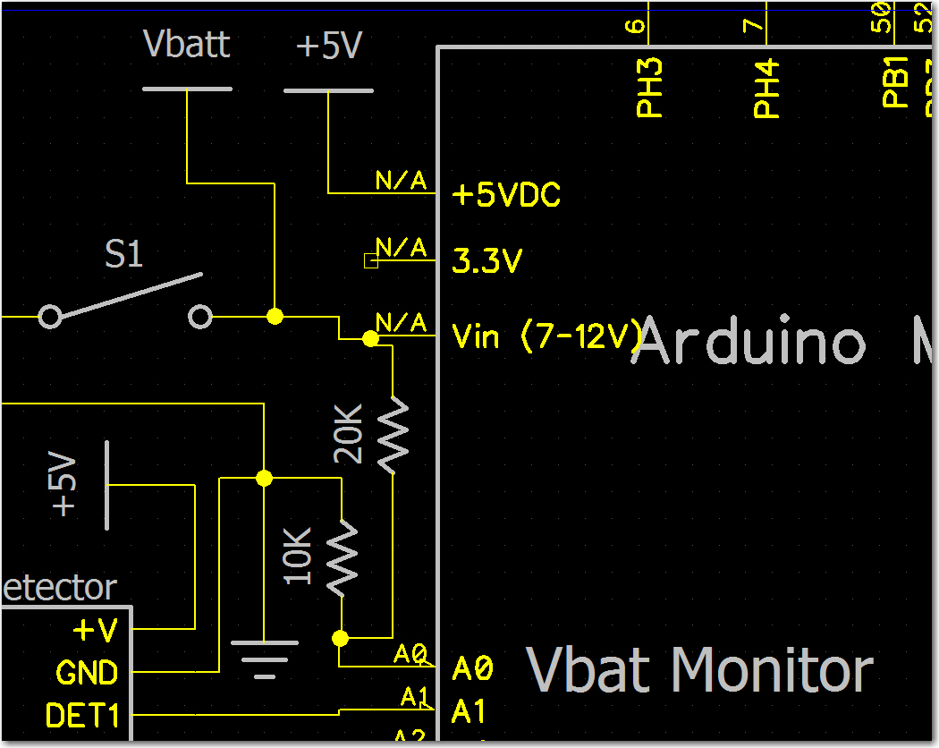
As part of the project to implement autonomous charging capability for Wall-E2, I needed a way to monitor main battery voltage in normal ‘run’ mode, in order to tell when to start searching for a charging station.  The main battery is a 2-cell LiPo stack, and so has a nominal stack voltage of around 7.5-8V when fully charged.  Since this is well above the Arduino Mega’s internal +5V operating voltage, I can’t measure this directly via the analog input ports.  So, I installed a 1/3-2/3 resistive voltage divider between the main battery voltage input, analog input A0, and ground, as shown in the following schematic detail.

System schematic detail showing resistive voltage divider for battery voltage monitoring

The nominal reading at A0 is 1/3VBatt.  Using the Arduino’s internal +5V regulator as the reference, the nominal battery voltage is 5*[A0/1023]*3.

To test this arrangement, I modified the operating software to print out the raw and calculated battery voltage values, and got the following printout.

BattMonVol: Raw 568 pin 2.78V TTL Batt 8.33V
BattMonVol: Raw 569 pin 2.78V TTL Batt 8.34V
BattMonVol: Raw 539 pin 2.63V TTL Batt 7.90V
BattMonVol: Raw 559 pin 2.73V TTL Batt 8.20V
BattMonVol: Raw 567 pin 2.77V TTL Batt 8.31V
BattMonVol: Raw 570 pin 2.79V TTL Batt 8.36V
BattMonVol: Raw 568 pin 2.78V TTL Batt 8.33V
BattMonVol: Raw 554 pin 2.71V TTL Batt 8.12V
BattMonVol: Raw 553 pin 2.70V TTL Batt 8.11V
BattMonVol: Raw 566 pin 2.77V TTL Batt 8.30V

In addition, I measured the battery voltage directly using my trusty multimeter, and got 8.03V, so a pretty reasonable monitor setup.


Next up; I had previously added the 4-detector IR module to the robot, and now I needed to integrate the IR detector measurements into the telemetry stream.  The battery monitor is on A0, and the 4 detectors are on A1-A5.  After adding the telemetry code, I got the following printout.

Now I will add back in the left/right/forward distances, the forward variance, and the left/right wheel speeds.  After adding everything back, I get the following telemetry stream:


Wall-E2 Charging Station Design, Part VIII

Posted 18 January 2017

In my last post on this subject, I had discovered  two major problems with my current strategy to free Wall-E2 from the need for human assistance.  The first problem was how to get Wall-E2 disengaged from the charging station, and the second was how to transition from charging power to on-board battery power without going through a power-cycle reboot.  As noted there, I decided there were two things I needed to do – install a MOSFET switch in the coil circuit so I could switch the relay back from ‘charge’ mode to ‘run’ mode before the external +5V charging voltage disappeared, and to connect the external +5V charging voltage through a blocking diode to the Arduino Mega’s +5V buss so the controller could continue to operate while the batteries were charging.

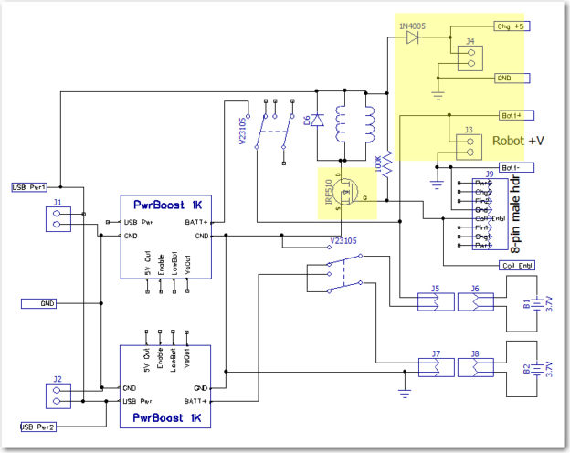
So, I made the above changes to the charger module, as shown in the image below (changed areas highlighted). For reference, the ‘original’ schematic has also been included
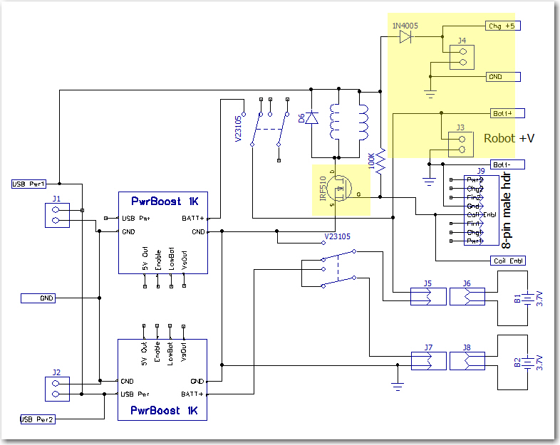
Dual Cell Charging Module with changes highlighted
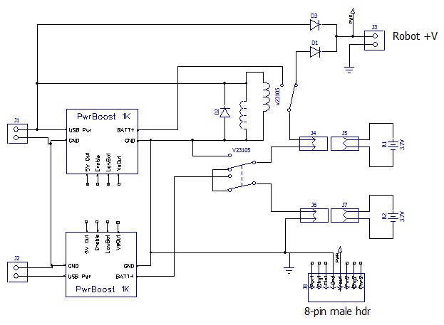
Dual cell balance charger. Note the two Axicom relays ganged to form the required 3PDT switch

As can be seen above, there are two major changes

  • Added a  IR510 n-channel enhancement mode MOSFET to control relay coil current via a new ‘Coil Enable’ signal rather than directly from the external +5V line.  A 100K pullup was added so that the default configuration of the MOSFET switch was ‘ON’.  A LOW signal on the ‘Coil Enbl’ line will switch the MOSFET to ‘OFF’, thereby switching the 3.7V cells from ‘charge’ (parallel) to ‘run’ (serial) mode.
  • Removed the blocking diode from the +7.4V ‘Robot +V’ line, and added a separate ‘Chg +5’ 2-pin terminal with a blocking diode.

After making these changes,  I set up an experiment where I could simulate the process of connecting the robot to the charger (thereby switching the batteries from the ‘run’ (serial) to ‘charge’ (parallel) configuration, with Arduino power being supplied by the external +5V line, and then disconnecting it using the new MOSFET circuit to switch the batteries back to ‘run’ (series) configuration before mechanically disengaging the external +5V plug.

Before conducting the experiment, I wanted to confirm that  the reboot problem still existed.   I set the robot up a small block so the wheels were off the ground, turned on the main power switch, waited while the robot booted up and the wheels began to turn (the program was configured  for continuous half-speed motion), and then engaged/disengaged the external +5V charging plug.  As expected, when the plug was engaged the wheels stopped turning but the Arduino continued to operate (confirmed by noting that telemetry readouts continued uninterrupted).  However, when I disengaged the plug, the wheels started turning again immediately, and the telemetry readouts continued unabated, indicating that no power-cycle reboot had occurred!  I ran this experiment several more times with the same result – after making the above changes, I could not get the robot to reboot in either direction – from ‘run’ to ‘charge’ mode or from ‘charge’ to ‘run’ mode. Amazing!

OK, so what caused the different behavior?  When I ran this same experiment before the changes, I saw an approximately 50msec gap between the time the external +5V line went away, to the time when the Arduino +5V line was again stable due to the +7.4V power via the regulator block. AFAIK, there were only three significant changes made to the charging module:

  • The IR510 MOSFET was added to enable/disable  the coils under computer control, with a 100K pullup to keep it in the ‘ON’ (low resistance) mode by default.
  • The external +5V line and its associated blocking diode was removed from the ‘Robot +V’ terminal to a new ‘Chg +5’ terminal
  • The blocking diode between the battery stack and the ‘Robot +V’ terminal was removed

So, what’s the deal here?  AFAICT there are only two possibilities:

  1. I didn’t/don’t fully understand the mechanism producing the 50msec power gap in the previous configuration
  2. I don’t fully understand why the current configuration  doesn’t have a 50msec power gap

Previous Configuration:

I am 100% certain that I observed a consistent, repeatable power-cycle reboot when switching from external +5V to internal battery operation, and I got the 50msec number from scope measurements .  To make the scope measurements, I triggered the scope trace on the falling edge of the external +5V line, and measured the time lag from that trigger to the time that internal battery voltage was available to  the Arduino.  The reboot phenomenon was verified by noting the long (5-10 sec) delay between the time the external power was removed to the time when the motors started running again, and by watching the interruption on the Arduino serial port.  The 50msec or so gap is consistent with the idea that it takes some time for the relay coil field to collapse after external power removal, plus the time required for the relay contacts to physically move from the ‘engaged’ to the ‘disengaged’ contacts.  During this interval, the only thing powering the Arduino is the charge left in the 680 uF power supply filter cap.  Assuming a current drain of around 100mA, it would take only about 5-10msec to cause a 1-2V drop on the +5V buss.  With the measured current drain of about 68mA, I  measured about 30msec for a 2V drop using my trusty O’scope, so this all tracks.

Current Configuration:

In the current configuration,    after the 2V drop, the voltage drops only very slowly, so the current drain must also drop significantly – could that be the answer?  Maybe most, if not almost all of the measured current drain is the coils themselves – so that after the blocking diode gets reversed, the drain out of the filter cap goes down by an order of magnitude or so, thereby letting the Arduino live on until the internal battery takes over?  Lets see – the specs for the Axicom V23105A5476A201  relay show 30mA for the coil current, times two relays gives about 60mA total.  The measured current with the relays engaged was about 68mA, meaning that when the diode blocks, the drain from the cap goes from 68 to 8mA, meaning an additional delta of 1V (from about 4.5 to about 3.5) should take 680X10-6/8X10-3 = 85msec, which is reasonably close to what I’m seeing on my O’scope.

That’s my story and I’m stick’n to it!

OK, so now my story is this:  In the previous configuration, the Arduino 6800uF filter cap supplied relay current  all the way down to zero volts, which meant that the voltage across the cap (and consequently, the Arduino working voltage) dropped to below 3V in less than 20msec, well less than the time required for the internal battery source to take over operation.  In the new configuration, the blocking diode between the external +5V supply line and the Arduino isolates the Arduino from the charging circuit after a drop of about 2V.  After this, the Arduino  is powered solely by the 6800uF cap, but because the Arduino’s current drain is  much smaller than the 60-70mA required by the charging circuit, the cap can power the Arduino for another 100msec or so, which is plenty of time for the internal power source to come on line.

One implication from this story is that the MOSFET circuit may not have been required at all.  As evidence, the gate of the MOSFET is tied to external +5 through a 100K resistor, so by default it is ON (low drain-source resistance) all the time, unless deliberately switched from the Arduino.  During all this testing, that control line  has been left open, meaning the MOSFET is just sitting there, doing its best to emulate a short length of wire. However, I’m reluctant to take it out or deliberately short around it for three  very good reasons (actually only one good reason, and two  not-so-good ones); first, it is just barely possible that the MOSFET actually turns OFF at some point in the process, maybe hastening the relay change from energized to de-energized (that’s a  not-so-good reason).  Second, it is a major PITA to disassemble the robot down to the point where I can access the MOSFET and install the short (another not-so-good reason). Finally, even if I do properly understand what is going on now, it is still possible that increased Arduino loads in the future will cause the reboot problem to re-appear; in this case, being able to de-energize the relays before disengaging from the charger will be a life-saver (that’s the good reason).  In addition, I’m unwilling to screw around with something that appears to be working just like I want it to (in other words – “if it’s working, don’t screw  with it!!”)

Where to from here?

As it stands, I have a robot that can be charged through its front-mounted external power jack, and should be able to  (assuming appropriate information availability) switch to internal battery power and disengage itself from the charging station.  Now I need to actually implement the entire solution, generally as follows:

  • Confirm that the proposed engagement/disengagement strategy will actually work.  To do this, I’ll need to modify the operating software to
    • recognize when the external power plug has engaged and is supplying power
    • switch back from external to internal power
    • disengage from the external power plug.
  • Build up the fixed portion of the charging station, including mounting the IR LED and supplying 5V power
  • Simulate the entire IR track/side-rail capture/engagement/disengagement cycle on the bench
  • Modify the operating system to implement the required additional tracking/movement modes

Independently of the above, I need to revisit the issue of how the charging station connects to the robot.  Originally, the idea was to connect via an array of contacts on the underside of the robot.  These contacts would mate with spring contact fingers on the top surface of a raised section of the fixed charging station, which would also contain status LEDs for the two embedded Li-Po chargers.  Unfortunately, I have been unable to come up with contact fingers appropriate for the application, despite trying three different contact finger ideas (EMI shielding finger stock, TE connectivity spring contact fingers, and Mill-Max spring-loaded contacts).  Fortunately, in the meantime I was able to successfully demonstrate  automatic external charging power connection using a guide funnel for the front-mounted external power jack and a semi-flexible probe tube with the mating external power plug mounted at its end.

The advantage of using the front-mounted jack for automatic power connection is that all I have to do is to get that one jack/plug pair engaged/disengaged, as opposed to the nine underside contacts.  This is a huge simplification of the problem, and one that I have already demonstrated to be feasible.  The major disadvantage of this option is that  all the charge-related decision making will have to be done by the robot, as the fixed part of the charging setup won’t know what is going on at all.  If I want to monitor charging status, I’ll have to do that via the onboard Arduino.  In the previous configuration (pre-MOSFET) this disadvantage was compounded by the fact that charging power could only be removed by physically disengaging the external power plug, which could only be done by some external physical mechanism since (by definition) the onboard wheel motors weren’t available during the charging process.  Since I now have a way around that dilemma (i.e. the robot can  now unilaterally switch from external to internal power by means of the MOSFET switch and then use the onboard motors to effect physical disengagement), this huge problem goes away entirely.  I still have the problem of how (or if) to display charging status, but this is trivial compared to the problem of physically disengaging the charging plug.

If I decide to abandon the underbelly contact array idea, then I can re-purpose the 8-pin header on the charging module to route charging status information to the Arduino instead of to the underbelly contact array. This header  is shown in the image below:
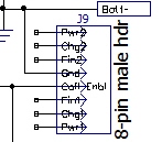
Charger module 8-pin male status/control header

As shown, there are 3 status pins for each cell charger, a ground line, and the new ‘Coil Enable’ line.  The status pins show whether or not the charger is receiving power (PWR), and whether the cell is still charging (CHG) or has finished (FIN).  In the original charging station design, the six status lines were brought out to individual LEDs via the contact array. If the underbelly array strategy is abandoned in favor of the single front-mounted connector, then these LEDs will have to be mounted somwhere/somehow on the robot itself.  Originally I was thinking that each status line would consume an Arduino Digital I/O pin, but now I’m not so sure.  All of these lines are actually already ‘powered’ from the charger modules themselves – all that is required to illuminate the CHG and FIN  LEDs is +5V – the status line is tied to an open-collector output through a limiting resistor.  The PWR status line is simply the +5V power to each cell charger, so a limiting resistor is required.  All the required signals and connections are available, so all that is needed is some sort of mounting arrangement on the robot – perhaps it could be integrated into the mounting for the front-mounted IR phototransistors in a manner similar to the ‘backup light’ mount at the rear?
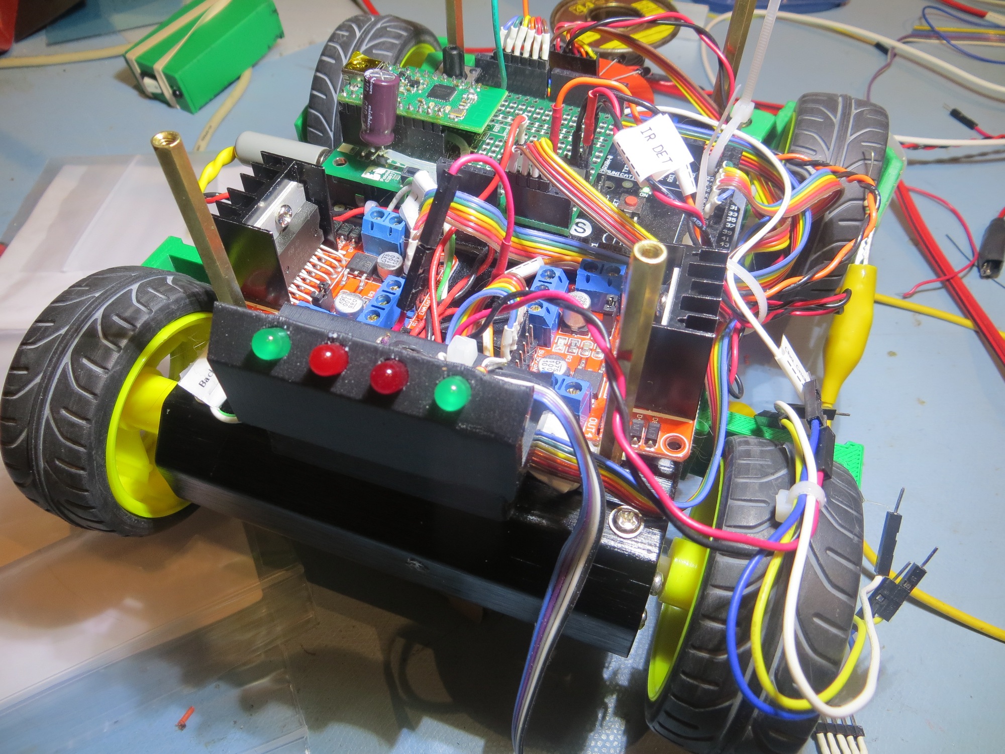
‘Backup Lights’ mounted to rear of the robot
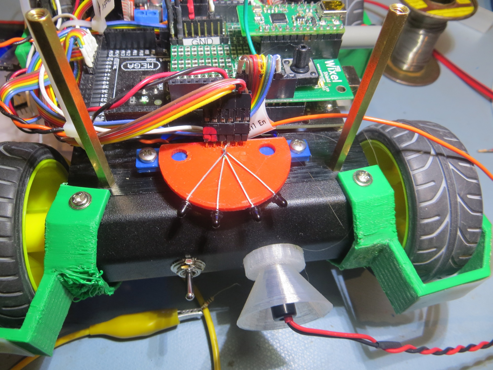
IR phototransistor mounting at the front of the robot

there would be more LEDs (7 vs 4) but each LED would be much smaller (3mm vs 5mm).  On the same 56mm panel, 7 LEDs could be spaced 6mm apart, with 6mm spacing on the ends, something like the following
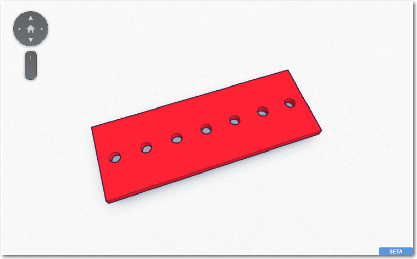
Prototype for a charging status LED panel

And, with my trusty PowerSpec PRO 3D printer I printed out  a full-scale feasibility assessment panel in just a few minutes, as shown below. Of course much more work would be required to make this into a fully functional panel, but just this piece shows that all 7 LEDs can be accommodated in a panel that is generally the same dimensions as the IR sensor module.
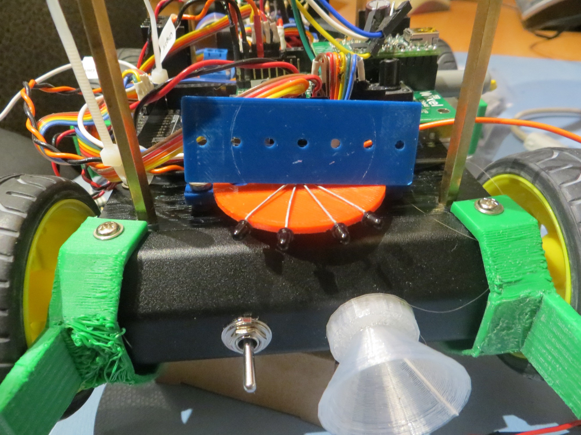
Charge status LED panel full-scale feasibility model

Charge Status Display Panel Update

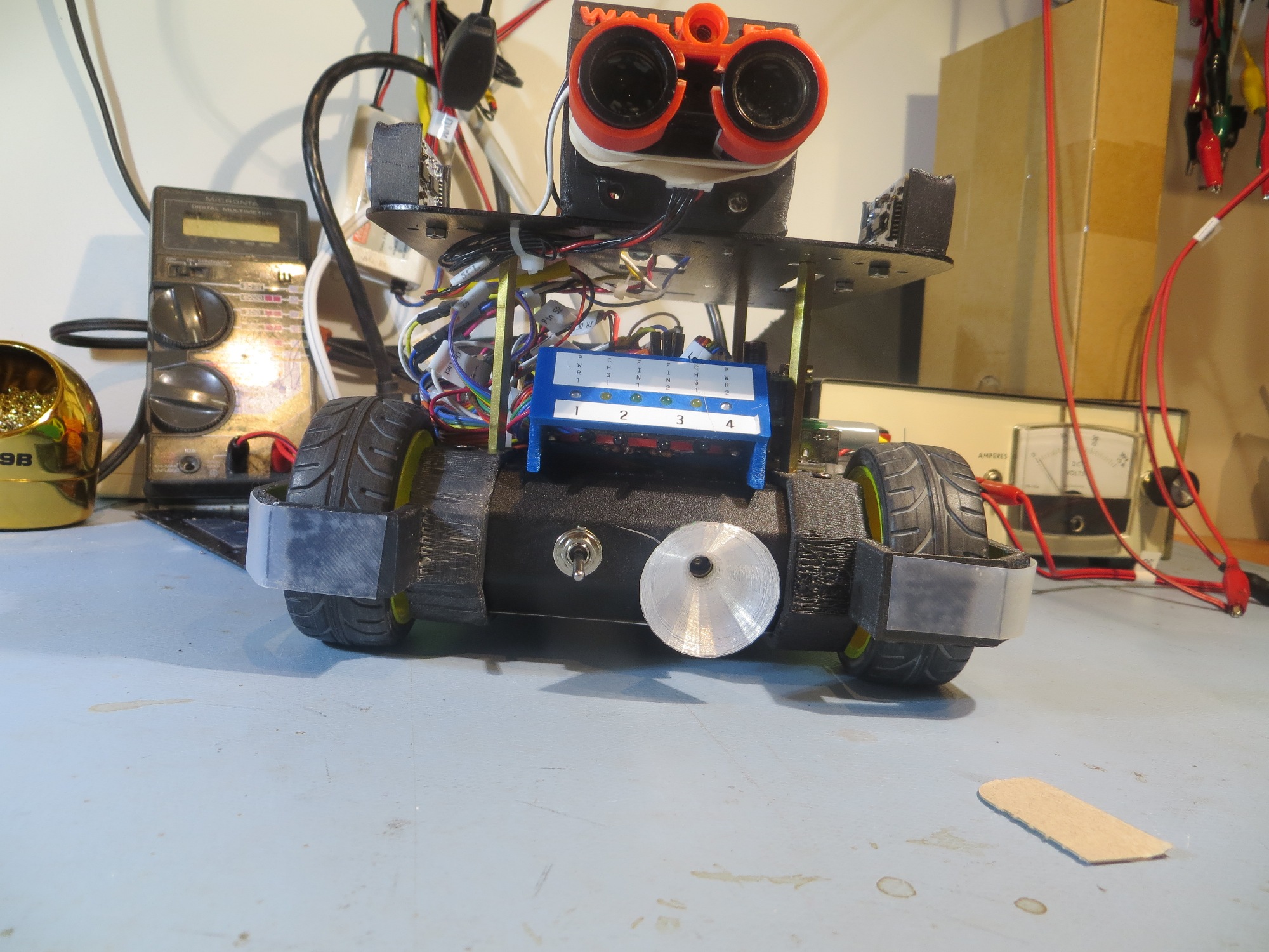
After the normal number of trials, I came up with a charge status display panel that could be co-mounted with the current IR detector assembly, as shown in the following images:
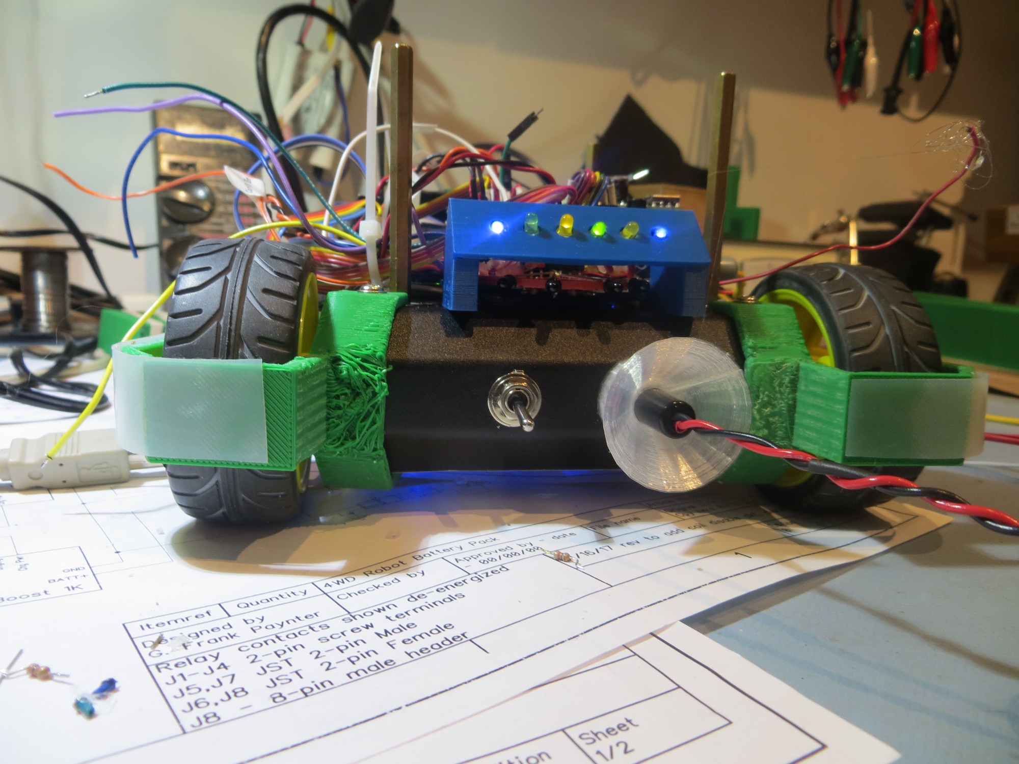
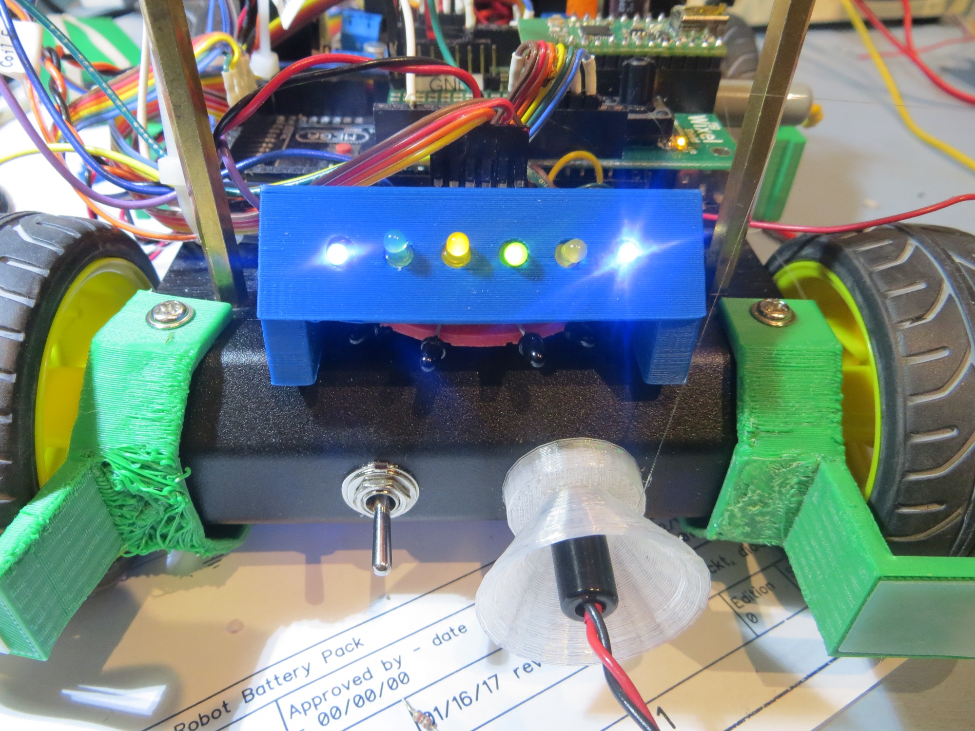
Stay tuned!

Frank


Wall-E2 Charging Station Design, Part VII

Posted 15 January 2017

I received my sample spring finger contacts from TE Connectivity, but they are clearly not going to do the job as the fixed end of Wall-E2’s under-belly contact system – bummer. Even the 4mm high one is just too small – bummer :-(.

As usual, when faced with a setback, I go away and sulk for a while, and then come back with some more ideas.  I may not be all that smart, but I  am persistent! ;-).  This time, after some more web research, I found a family of spring-loaded plunger contacts made by Mill-Max  Inc, one of which is  shown in the image below

Spring-loaded contact. Initial height is 7.67mm, compresses down to about 6mm

As an interesting aside, the Mill-Max components are (AFAICT) dimensioned entirely in English units (inches), which is of course what I grew up on here in the U.S.  However, after the last few years of immersion in the 3D printing and robotics world, I have gotten to the point where I had to convert the above ‘0.302″‘ dimension into  metric units (around 7.6mm) before I could visualize how (or even whether) it was going to fit into the current design.  Even more interesting, I was an electronics design engineer in a DoD outfit during the Carter administration’s failed attempt in the 1970’s to convert the entire U.S. to metric.  There was an enormous amount of work put into relabeling everything with both English and metric notation, to absolutely no effect.  The reason it failed then, and is working now (at least for me) is the widespread use of metric notation now for 3D printing and DIY robotics.  Way to go, Carter – you had the right idea, just  50 years too soon! ;-).

Anyway, back to the movie; while waiting for the above parts to arrive, I have been doing some additional work on the alternative plug-capture strategy, and came up with three additional design issues that must be resolved for either the bottom contact array or the front plug-capture methods.

  • In order for either method to work, the robot has to know when the contacts have engaged, so it can change from a wall-following to a charge-monitoring  strategy.
  • The robot’s controller has to continue operating through the change from battery power to off-board charging power.  The  transition from battery power to off-board charging power is inherently seamless, as charging power to the Mega’s +5V (beyond the voltage regulator stage) pin appears before the batteries are switched from series to parallel for charging.
  • When charging is complete, the robot has to somehow disengage from the charging system.  This turns out to be somewhat of a trapeze act, as motor power to do the disengaging isn’t available until after disengaging – oops!
  •  Although the transition from battery to charging power is inherently seamless, the opposite transition isn’t.  5V power from the charger goes away  before battery power becomes available, causing  the Mega to  reboot – double oops!

Knowing when contacts have engaged

For the robot to know when the contacts have engaged, there has to be some electrical signal that changes state when this happens.  For the case where the forward 5V plug is engaged, this was  accomplished by connecting the normally-closed contact of the power jack to a digital input, with the pullup resistor activated; This causes a low-to-high transition when the contact is broken, which occurs when the power plug fully engages in the jack.   However, this signal isn’t available when the under-belly contact array is  utilized.  For this case, the plan is to tap off the ‘Pwr1’ and ‘Pwr2’ signals and run them to digital inputs; these lines are normally LOW, and transition to HIGH when charging power is available.

Continue operation through transition from battery power to charging power

As noted above, this is inherently seamless, as charging power is available before battery power goes away.  All that is required is to wire +5V charging power to the Mega’s +5V output line (i.e. after the regulator stage).

Disengage from the charging station after charging is complete.

As noted above, this is a problem, because  the motors require 7.4VDC battery power, which isn’t available until about 50msec after the charger is disengaged.  So, either some way will have to be found to run the motors from the +5V charger power, or some way will have to be found to physically disengage the robot from the charging station  without using the motors.

One way to skin this cat is to implement some sort of pusher  mechanism on the charging station side, like a linear actuator or a solenoid or a stepper motor.  The idea would be that the charging station pushes the robot off the charging plug and/or underbelly contacts.  The problem with this scenario is that the charging station doesn’t necessarily know when charging is complete, especially if the front plug/jack option is being used.  If the underbelly contact arrangement proves viable, then the ‘FIN1’ and ‘FIN2’ LED enable lines are available for this function.

Another idea is to use the same sort of pusher mechanism, but put it on the robot side.  The advantage of this arrangement is that the robot can easily tell when charging is complete (the above ‘FIN1’ and ‘FIN2’ signals).  However, there are two significant disadvantages; first, there is the issue of how to mount a pusher mechanism – there isn’t a whole lot of idle real estate on the robot – especially on the front surface.  Secondly, as soon as the pusher mechanism successfully disengages the robot from the charger station, the power to run the pusher will go away for at least 50msec – which could lead to a mechanical oscillation condition.  Some mechanical hysteresis will have to be engineered in to make sure that once the pusher starts the disengagement process, it will complete it with plenty of margin (maybe a mechanism that winds up a spring using charger power, and then the spring actually does the pushing, or a solenoid that once triggered, completes the stroke regardless of power availability?)

Computer reboots when charging power is removed

The +5V power to the battery chargers also drives the two relay coils, which among other things, switch the two 3.7V battery packs from series to parallel connection for charging.  In addition to charging the batteries, this +5V line is connected to the Mega’s +5V buss, downstream of the voltage regulator circuit. This allows the Mega to continue operations during the transition from ‘run mode’ (powered by the 7.4V battery stack via the voltage regulator) to ‘charge mode’ (directly powered by the +5V charging voltage).  However, when the +5V power is removed at the end of the charging cycle, there is an unavoidable gap of about 50msec where there is no power available for the Mega.  This means that the Mega will perform a cold-boot at the end of each charging cycle, just as if it were being turned on for the very first time.  In other words, the Mega won’t know where it is, and certainly won’t know that it was just disconnected from the charging station. Without some additional work, the robot will assume it is starting out life anew, and will immediately start trying to follow the nearest wall (and/or trying to home in on an IR signal if one is present – and one certainly would be if it had just disconnected from the charging station).  Moreover, since the robot by definition would be well inside the capture rails for the charging station, it would most likely just plug itself back into the charger – rinse, lather, repeat ;-(.

One possible solution for this dilemma would be to store a non-volatile ‘bWasJustCharged’ flag in the Mega’s EEPROM.  This flag could be checked at boot time; if the flag is set, then the robot knows it was just disconnected from the charging station and can take the appropriate action; if not, then party on as normal.  Maybe something like the number of milliseconds since  the last charge operation?  The nice thing about this idea is it could also be used as a crude battery level meter, assuming battery usage was somewhat linear over time.

15 January 2017 update:  Just confirmed that I can store and retrieve information to/from the Mega’s EEPROM.  I had a small EEPROM write/read test program lying around from a couple of years ago (I did tell you that I  never throw anything away, didn’t I), and used it to update an EEPROM location with the current value of millisec() every second or so.  In the setup() function of this program, I read the same location (i.e. the initial read comes  before the first update in the loop() function).  I ran the test by letting the Mega run for 10-15 seconds, thereby assuring that the EEPROM value was in the 10-20,000 range, and then power cycled the Mega.  The initial readback after the power cycle was in the correct range (i.e. 10-20,000), confirming that the elapsed run time had survived the power cycle.  For my project, I think I can set a threshold like 15-60 sec for just-charged detection; if the stored value is less than the threshold, the robot decides that it has just been disconnected from the charging station, and takes the appropriate action (backs out of the side rail capture area, turns 180, and gets the heck out of Dodge.  As a secondary benefit, the robot can consult the ongoing elapsed time counter to decide how actively it should look for ‘food’ (charging station).

16 January 2017 update:  I tried a couple of ideas for mechanically disengaging the robot, with absolutely no success – it turns out the robot is actually quite heavy, and in addition it has to be moved against the motor gearing on all four wheels.  Not going to happen without a serious motor!  So, back to the drawing board again.  After a while, I realized that I was thinking about the problem (actually two of the problems)  the wrong way.  The two problems are the need to disengage the robot from the charging station, and the need to deal with the reboot  that occurs when the robot is disengaged.  It occurred to me that  if the batteries could be switched back from parallel to series operation  before the robot was disengaged, two very good things would happen; first, I could then use the robot’s own motors to perform the disengagement task – rather than having to fight the motors using an external actuator. Secondly, this would eliminate the reboot problem entirely, as the 7.4V source would provide 5V through the regulator to the Mega’s 5V node, meaning no interruption when the charging +5V disappeared.

To make all this happen:

  • I need to install a blocking diode on the +5V charging line to the Mega +5V node, so that when the 7.4V source reappears and takes over the power supply function, that there won’t be any backwards current on the +5V charging line
  • I need to be able to disable the current to the two relay coils, while still maintaining +5V power  to the Mega +5V node, and this needs to be controllable using a Mega digital output (i.e. max 30mA source/sink).  This can be accomplished by adding a n-channel enhancement mode MOSFET to the circuit, between the +5V charging input and the relay coils, as shown below.  The MOSFET should  be ‘normally-closed’ (i.e. low D-S resistance), so this can be accomplished by connecting the gate to a digital output with the pullup resistor engaged.  Then a LOW output will turn the MOSFET OFF (high resistance) thereby de-energizing the relays, which will in turn switch the batteries from parallel to series operation.  After a suitable delay for this to happen, the robot can then use its own motors to disengage and move away from the charging station.

18 January 2017 update: So, I made the above changes to the charger module, as shown in the image below (changed areas highlighted). For reference, the ‘original’ schematic has also been included

Dual Cell Charging Module with changes highlighted

Dual cell balance charger. Note the two Axicom relays ganged to form the required 3PDT switch

As can be seen above, there are two major changes

  • Added a  IR510 n-channel enhancement mode MOSFET to control relay coil current via a new ‘Coil Enable’ signal rather than directly from the external +5V line.  A 100K pullup was added so that the default configuration of the MOSFET switch was ‘ON’.  A LOW signal on the ‘Coil Enbl’ line will switch the MOSFET to ‘OFF’, thereby switching the 3.7V cells from ‘charge’ (parallel) to ‘run’ (serial) mode.
  • Removed the blocking diode from the +7.4V ‘Robot +V’ line, and added a separate ‘Chg +5’ 2-pin terminal with a blocking diode.

The idea was to set up an experiment where I could simulate the process of connecting the robot to the charger (thereby switching the