Tag Archives: robots

TP5100 2-cell LiPo Charger Module Study

Posted 24 February 2018

I have been working on Wall-E2, my autonomous wall-following robot, for almost three years now, and it seems like I have been struggling with the battery and charger arrangement for that entire time.   I started out with 4 AA batteries, but quickly moved on to a pair of Sparkfun 2000mAh ‘flat-pack’ cells with Sparkfun chargers, with a relay to switch the batteries from series (RUN) to parallel (CHG) wiring.   This worked, but not very well.   The flat-pack batteries weren’t a good match for motor control, and I kept burning up charger modules as well.   After struggling with this through several iterations, I finally abandoned it entirely in favor of a 7.4V 20C LiPo RC battery and an external charger. This worked much better, but forced me to manually disconnect the battery from the robot and charge it externally – not at all what I wanted.   Later on I made another run at the 2-cell series/parallel switching strategy for charging, this time using Adafruit Powerboost 1000C charge modules, each capable of 1A charge rates. Again this worked (actually quite well), but I recently discovered that it has a fatal flaw – this design imposes significant IR drops on the way from the battery terminals to the motors.

So, I have once again been searching for a solution to the battery/charger problem.   While wandering through the Googleverse the other day, I ran across a mention of the 1/2-cell TP5100-based charger module (about 9:50 from start), available for next to nothing on eBay.

Unfortunately, the available technical information on this module is also next to nothing, and what does exist is all in Chinese.   Still, this module has the potential for vastly simplifying my charger setup, so I thought it was worth the effort to perform a thorough study.

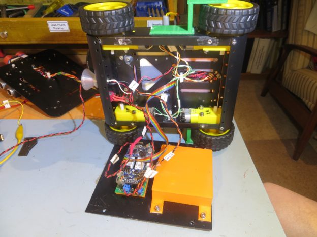
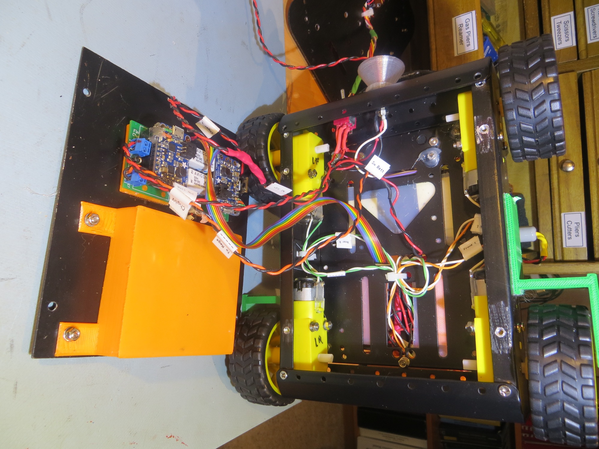
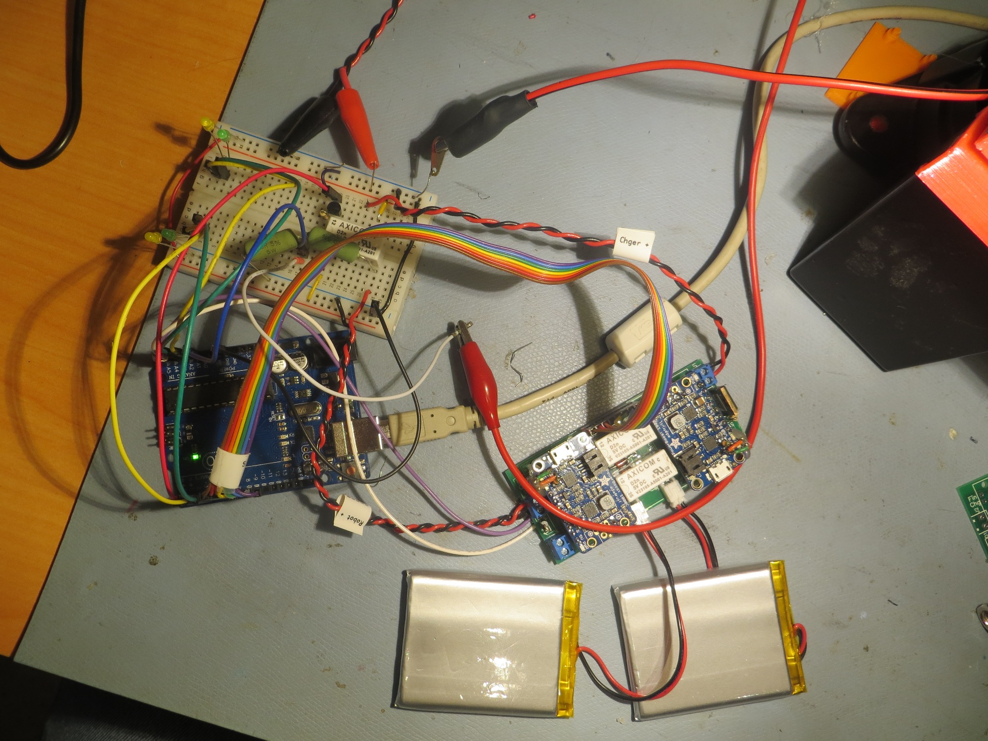
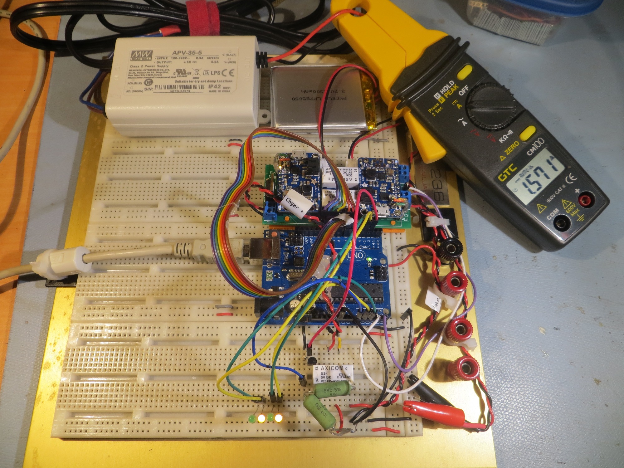
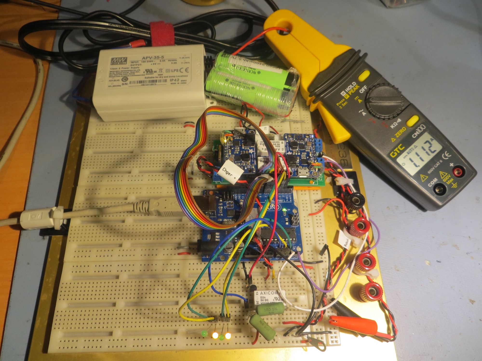
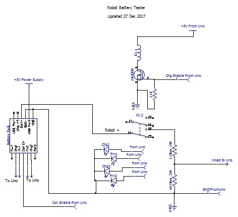
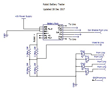
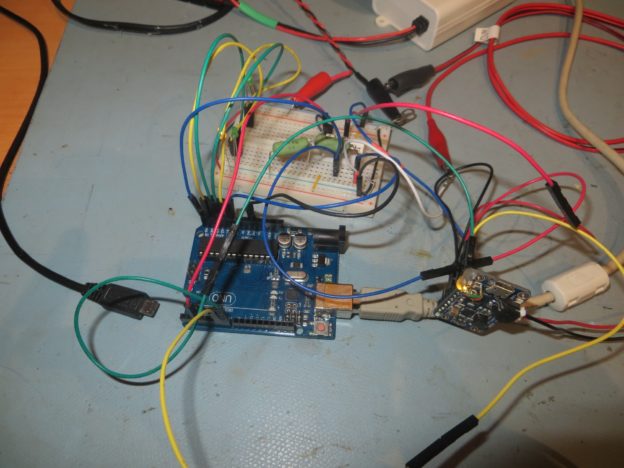
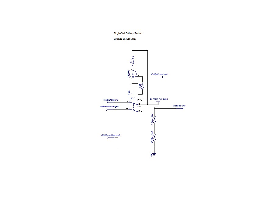
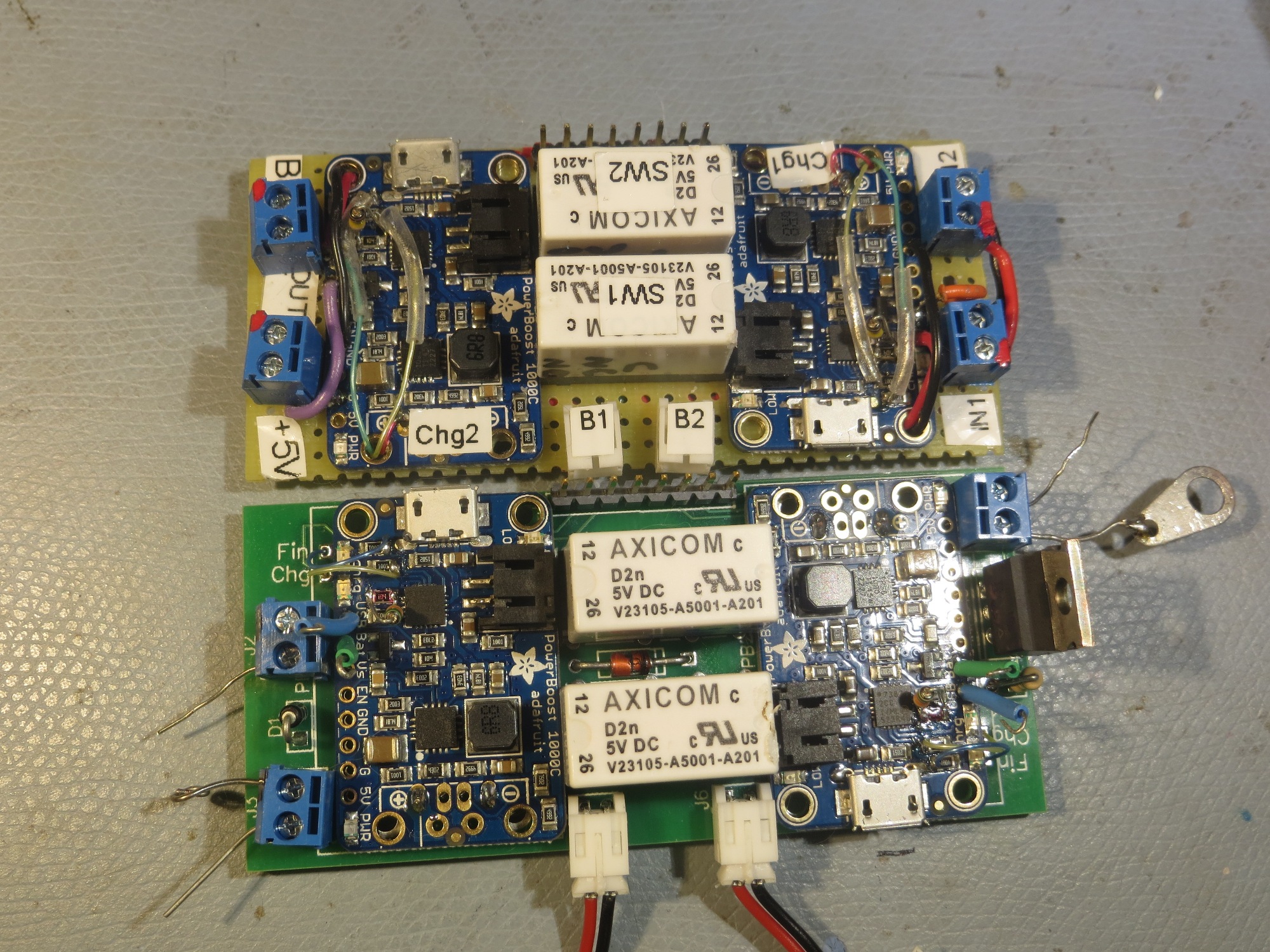
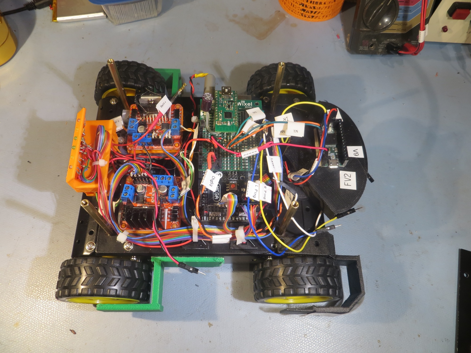
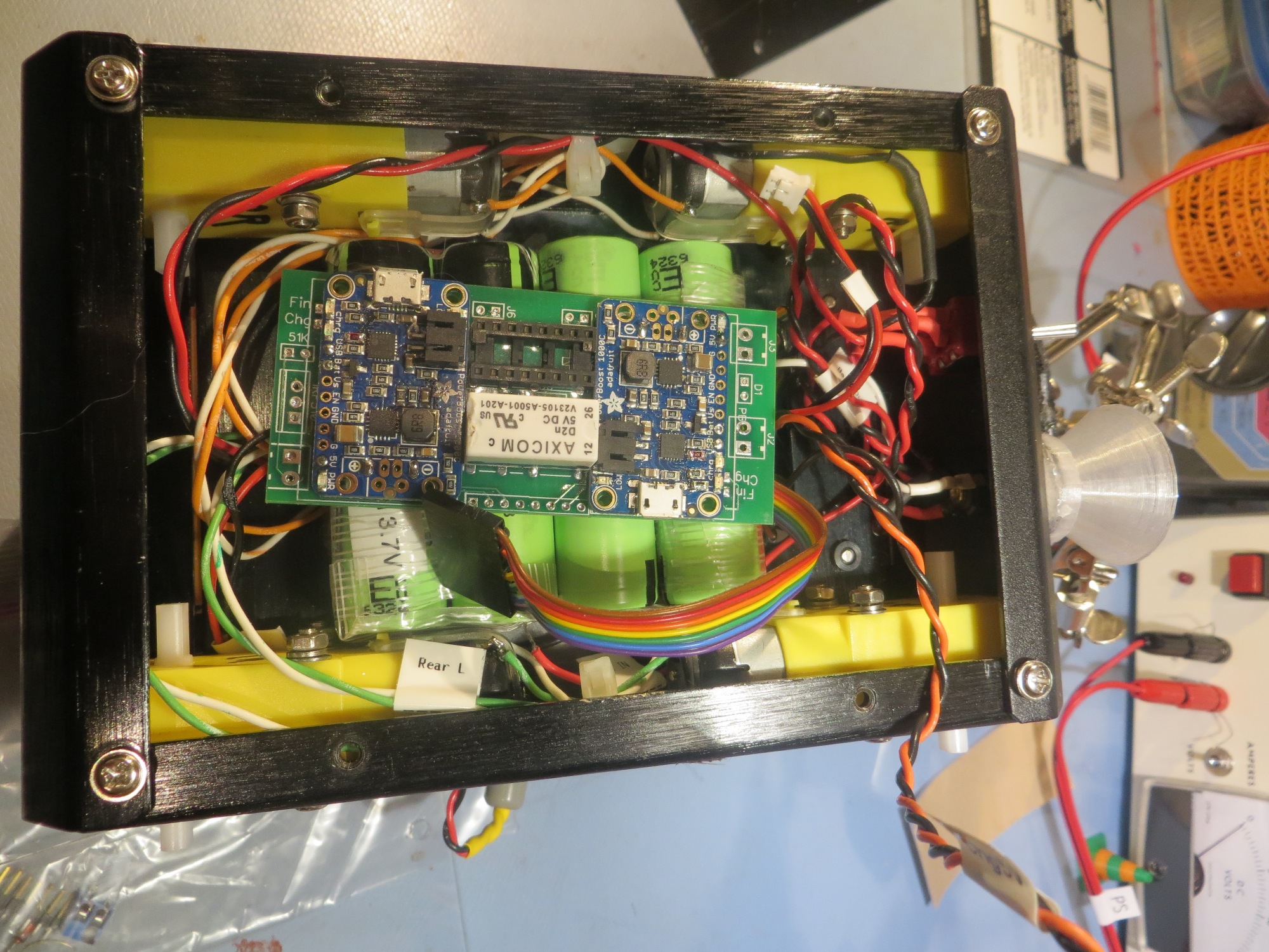
In a previous post, I described an Arduino controlled charge/discharge test setup for testing operation of my 2-cell parallel/series switched setup, so I decided to modify it for evaluating the TP5100 module, as shown below

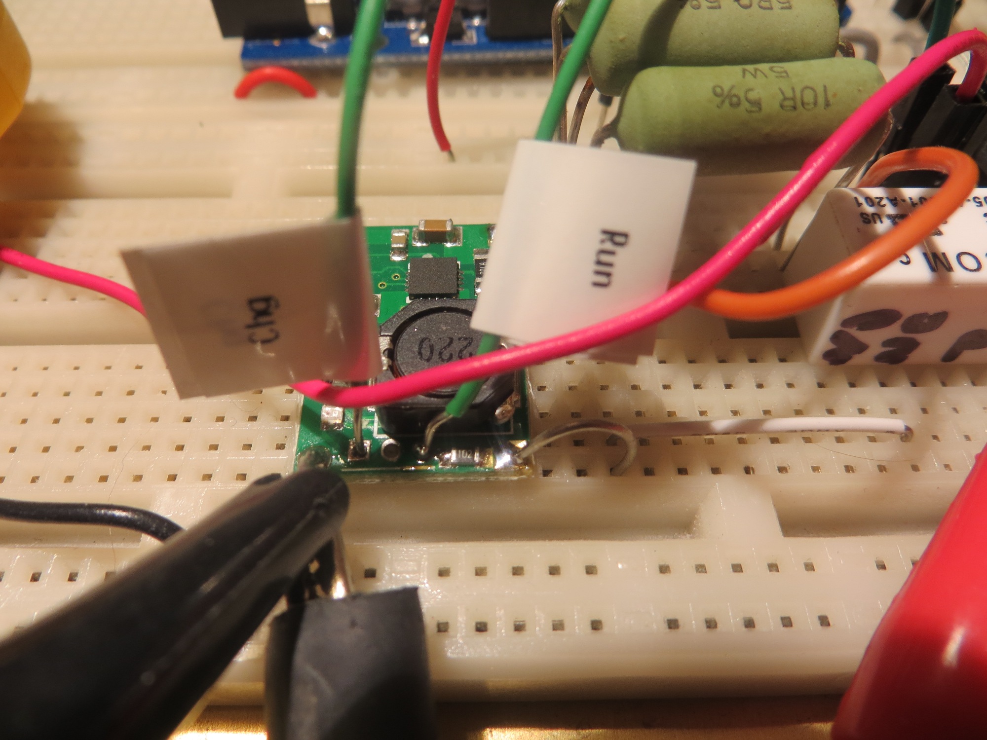
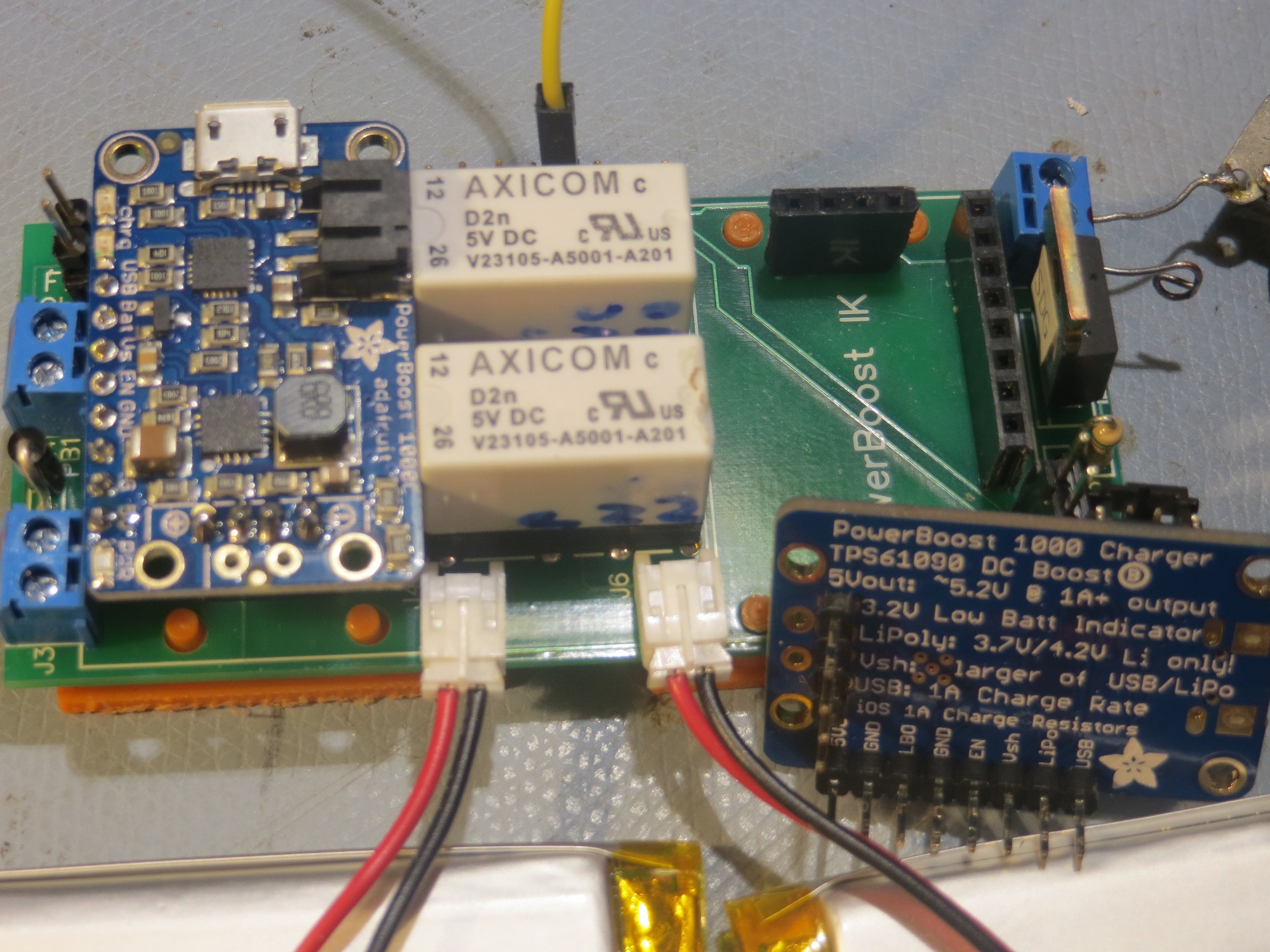
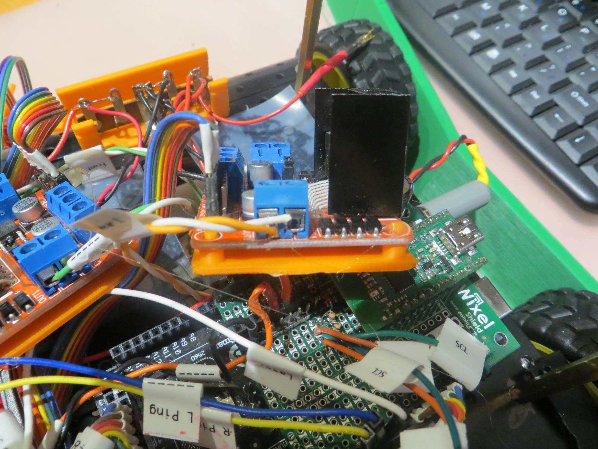
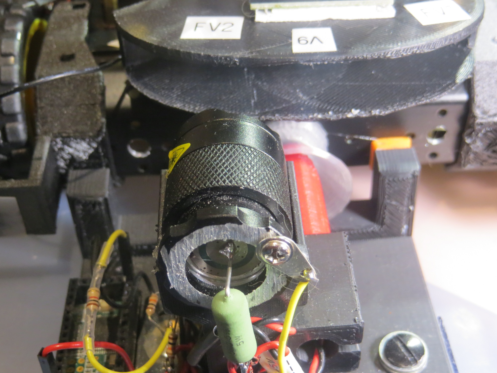
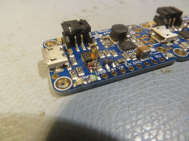
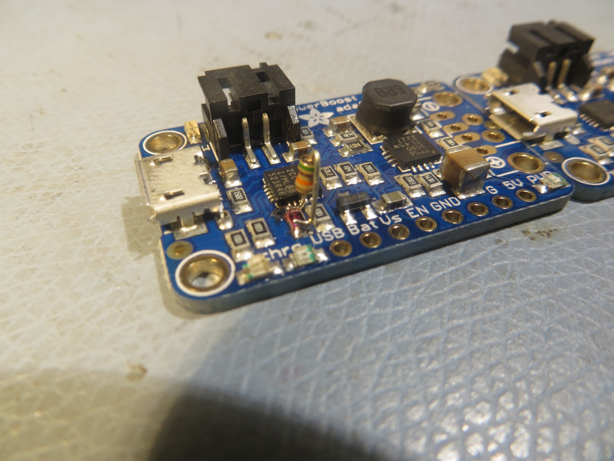
View of TP5100 module showing RUN & CHG indicator connections

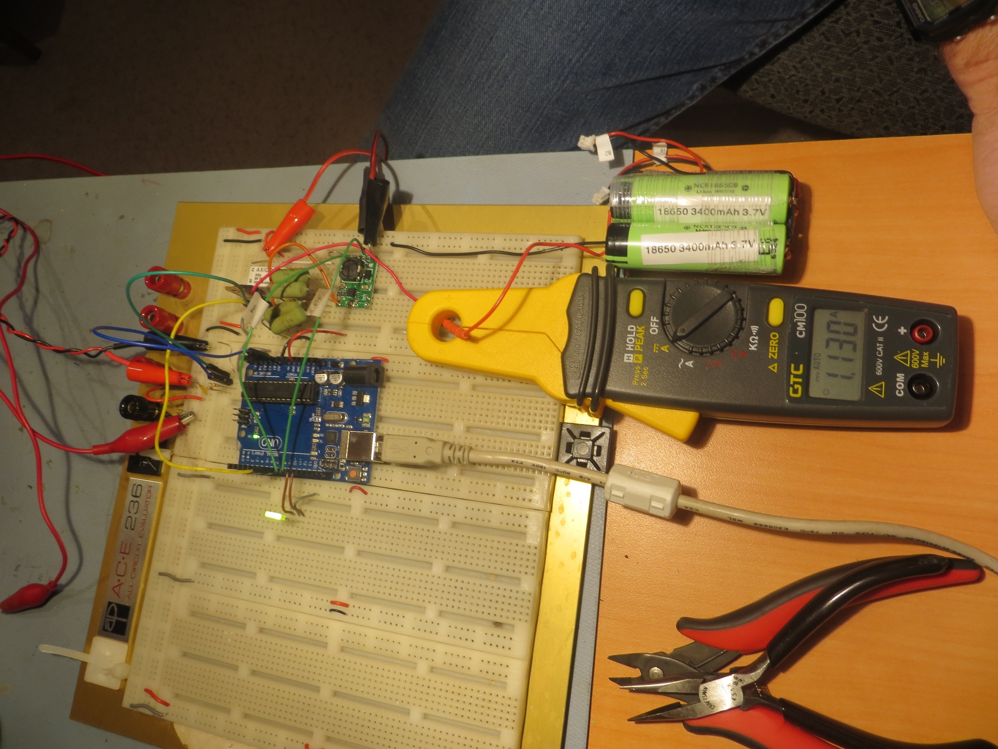
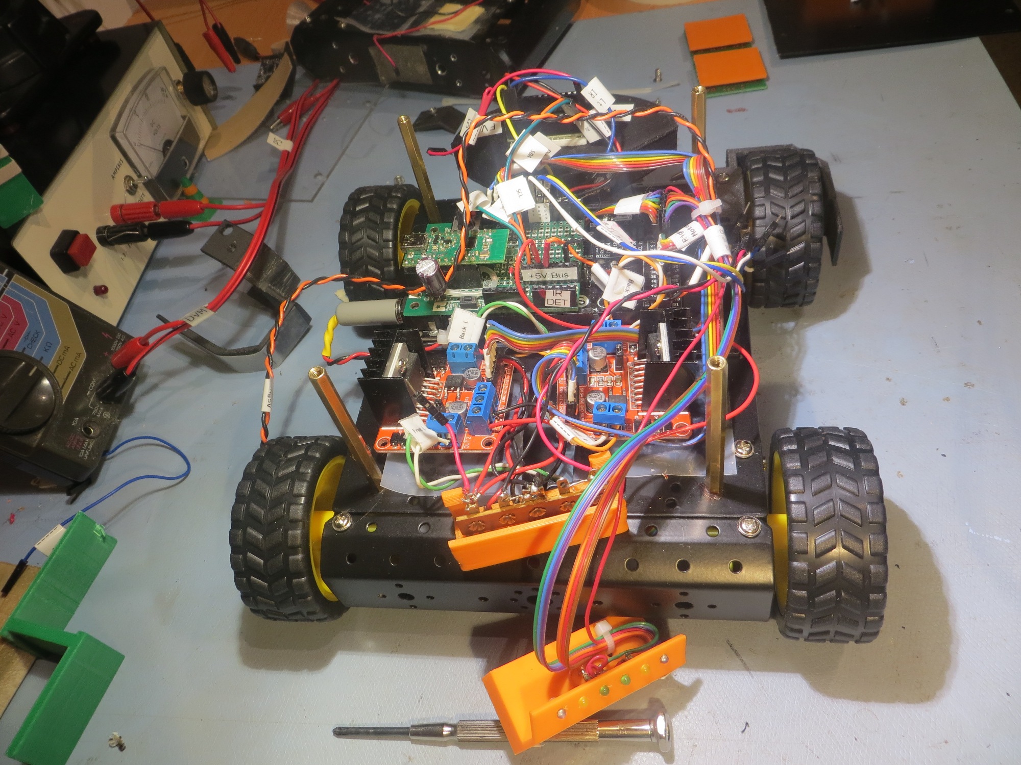
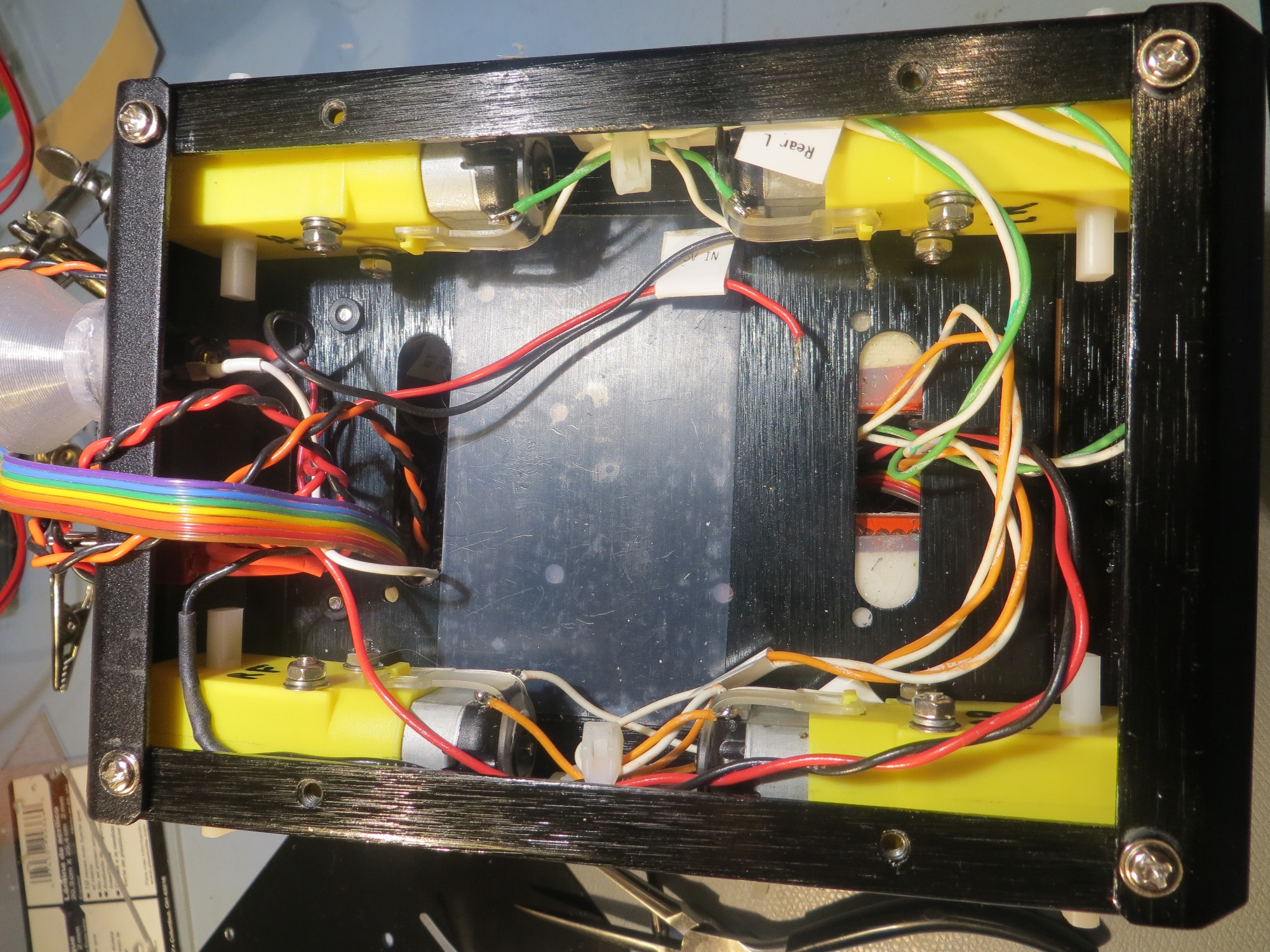
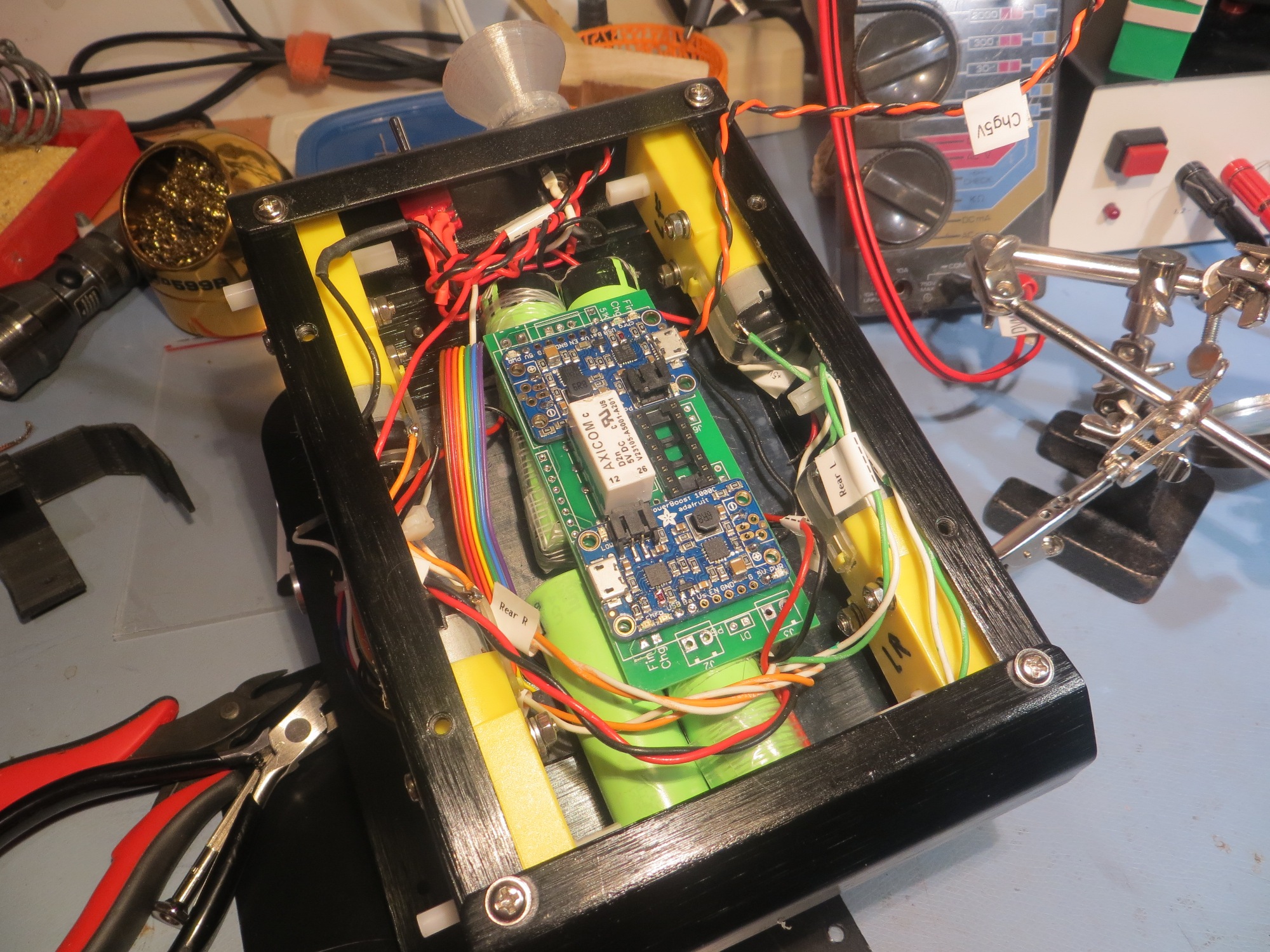
Charger test setup, in discharge mode (note 1.1A discharge current)

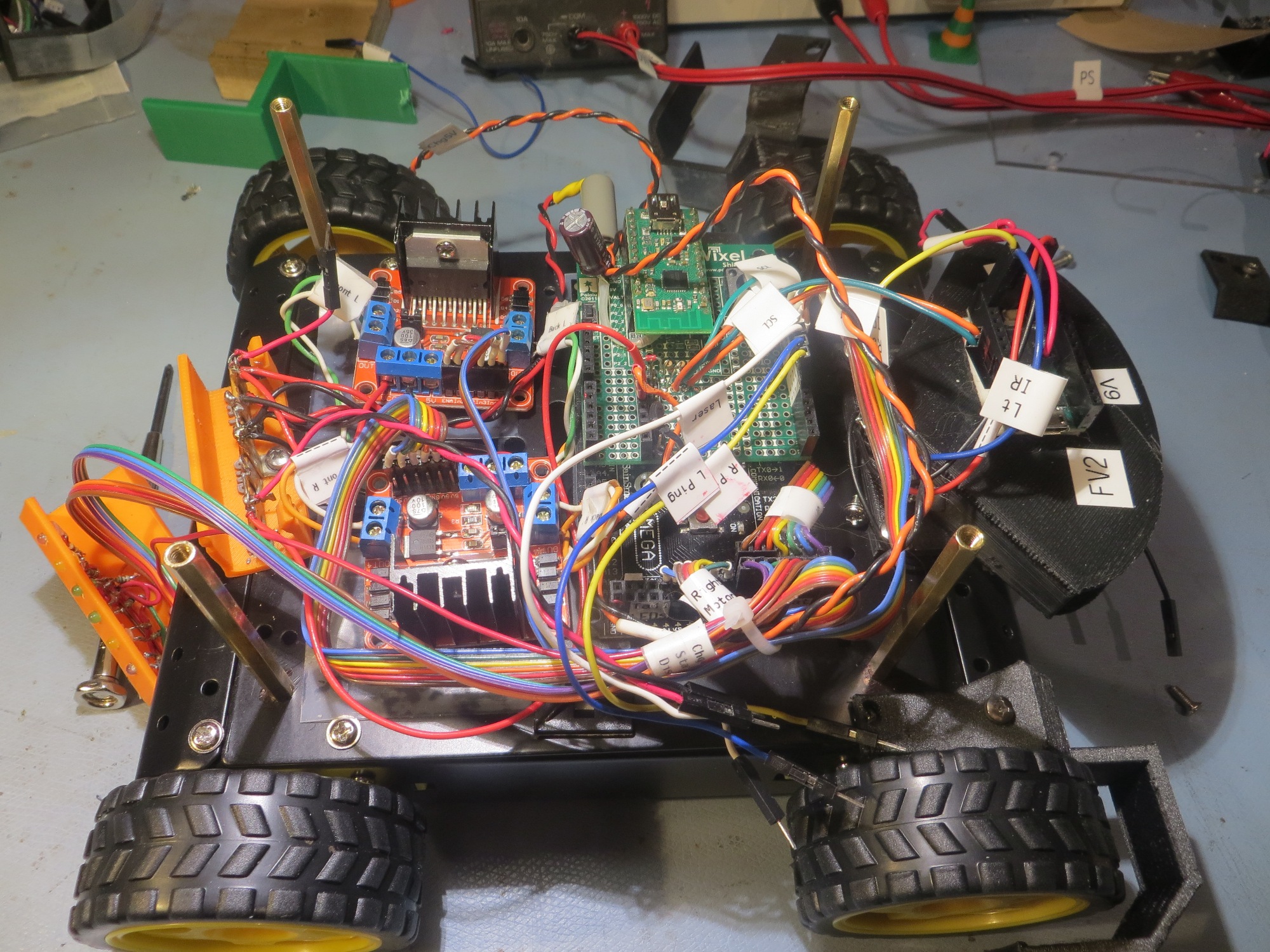
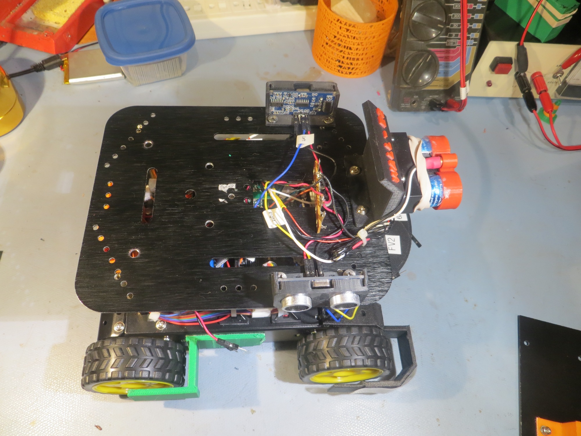
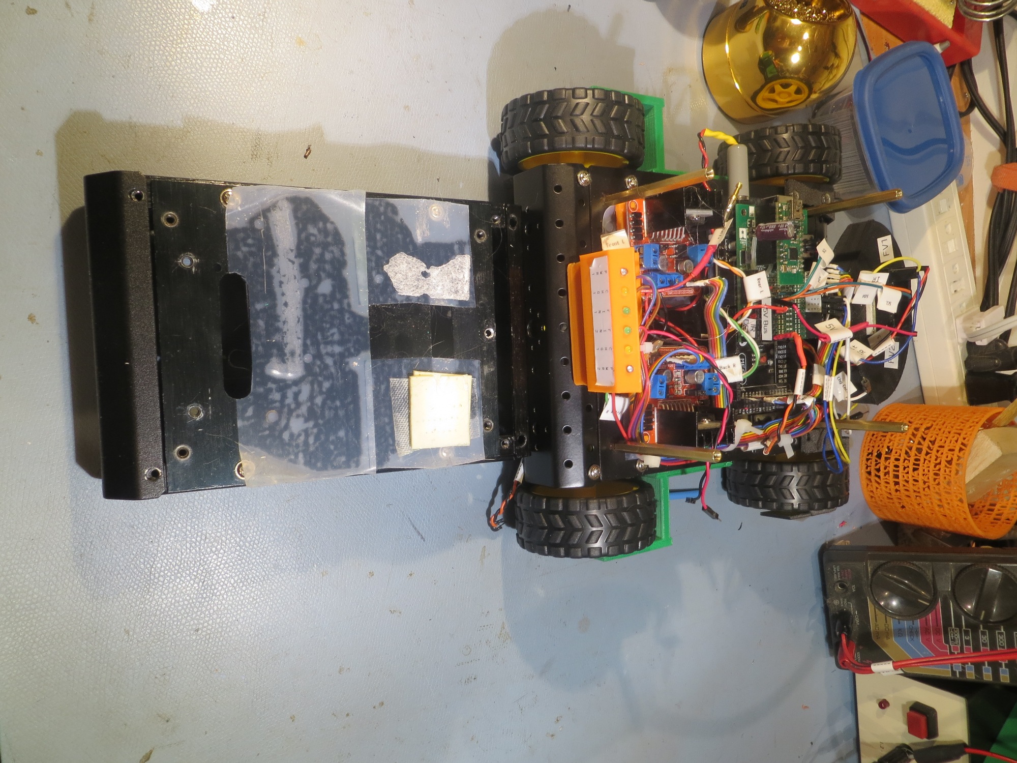
Charger test setup, in charge mode (note 1.8A charge current)

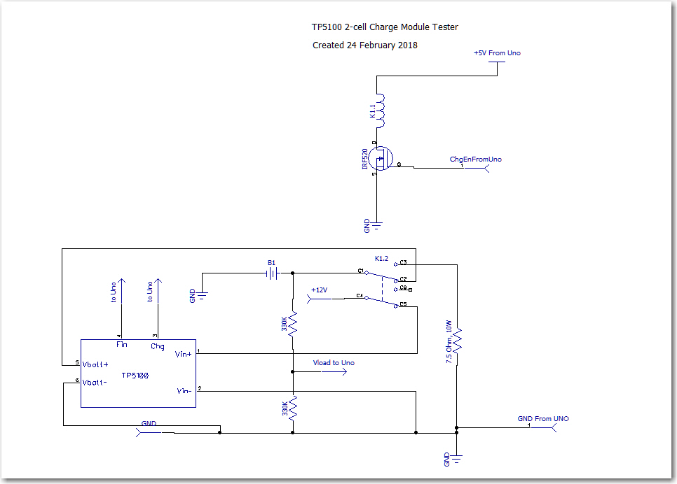
TP5100 Module Test Circuit

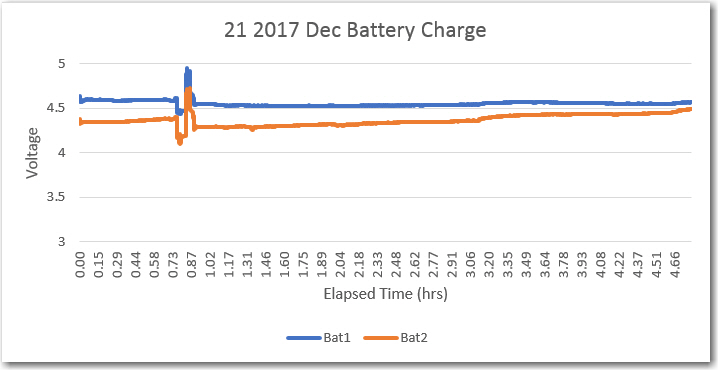
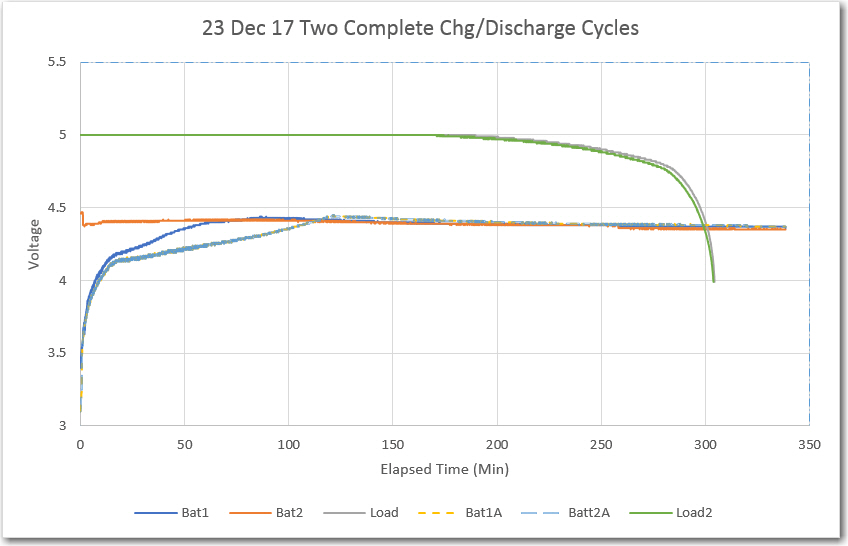
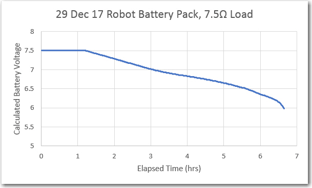
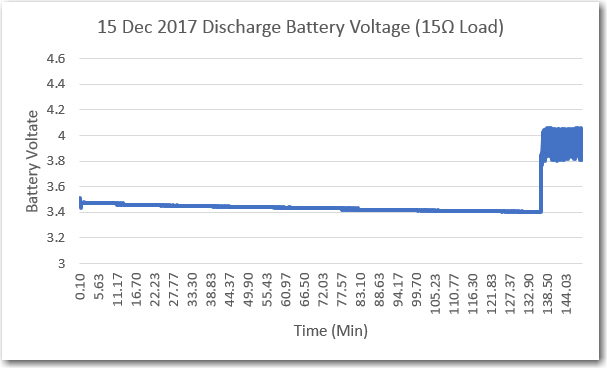
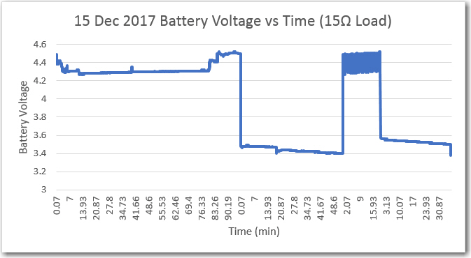
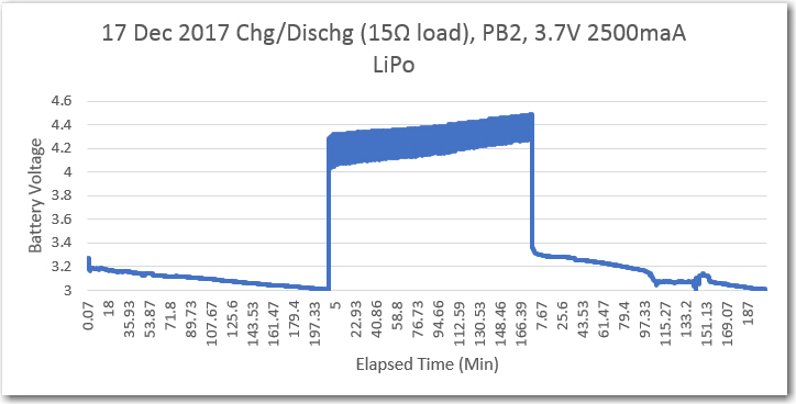
Using this setup, I was able to cycle the battery between a 7.5V load and the TP5100 charge module.   In order to keep the cycle times down to a dull roar, I set the software to switch to charge when the battery voltage dropped below 7.5V, resulting in the plots shown below.

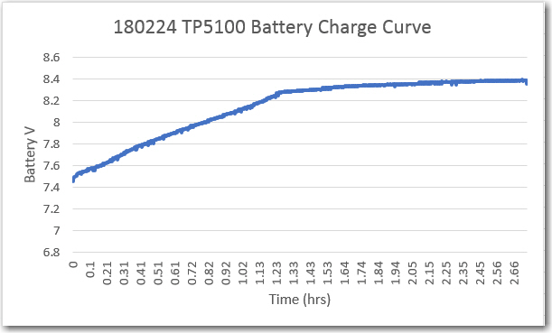
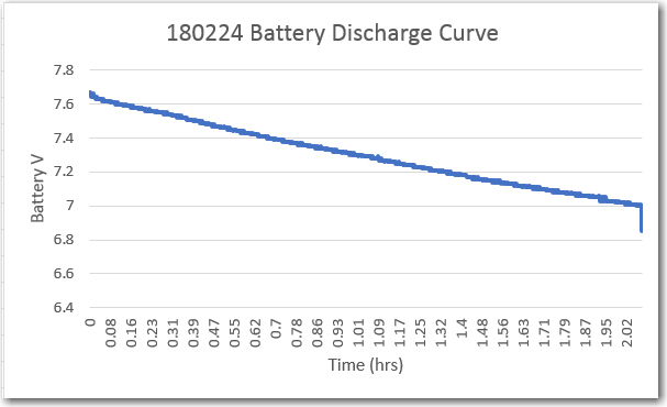
In this case, the discharge current was about 1.1A, and the observed charge current was about 1.8A.  The TP5100 modules seems to work as advertised – with a 12V 5A power supply and a partially charged battery, it successfully charged my 2-cell LiPo pack terminated the charge at about 8.4V (I’m not sure if it is terminating based on current or voltage).

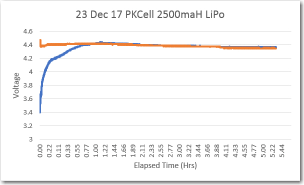
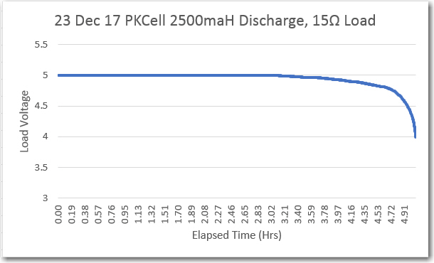
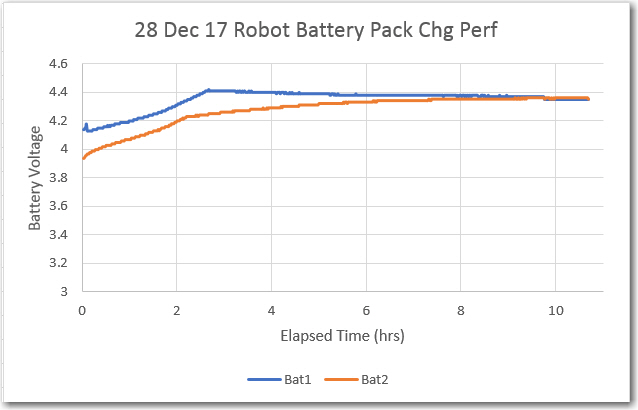
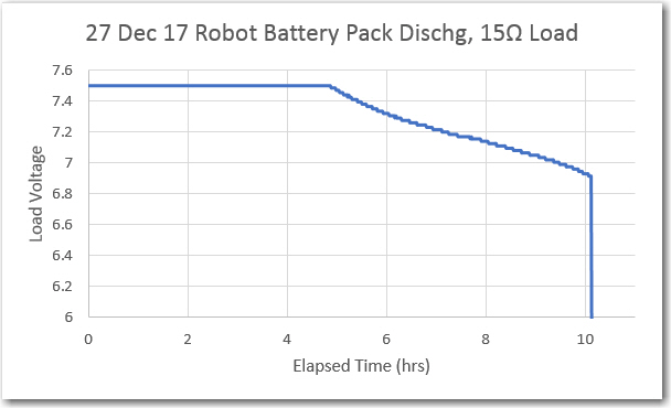
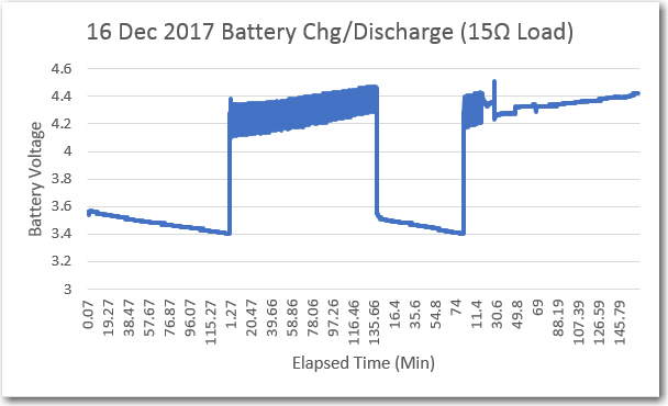
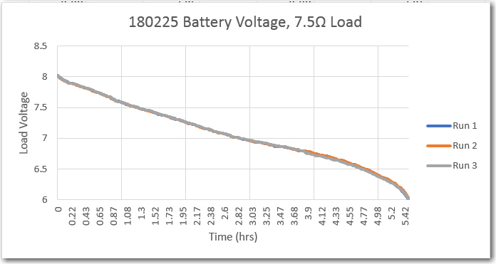
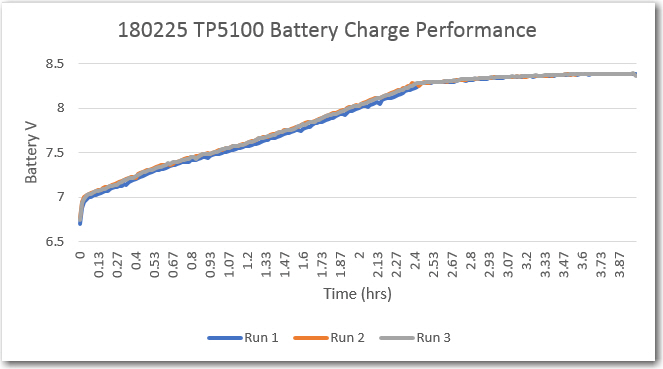
Over the next couple of days, I performed three complete charge/discharge cycles using this same setup.   Discharge was terminated at 6V, and charge was terminated when the TP5100 ‘complete’ output changed from open-circuit to active-low. As can be seen in these charts, performance was very consistent – almost 6 hours run time  into a 7.5V load, and about 4 hours for a complete recharge.


So here’s what I know now about the TP5100 module

  • When the ‘1-cell/2-cell’ jumper selector is shorted to select 2-cell, the output voltage stabilized at 8.4 with a 10-15V DC input (I used a 12V 5A supply for the tests).   Below about 10V, the output voltage falls below 8.4V
  • with a partially charged battery stack, output current was about 1.8A at the start, tapering to below 200mA at termination
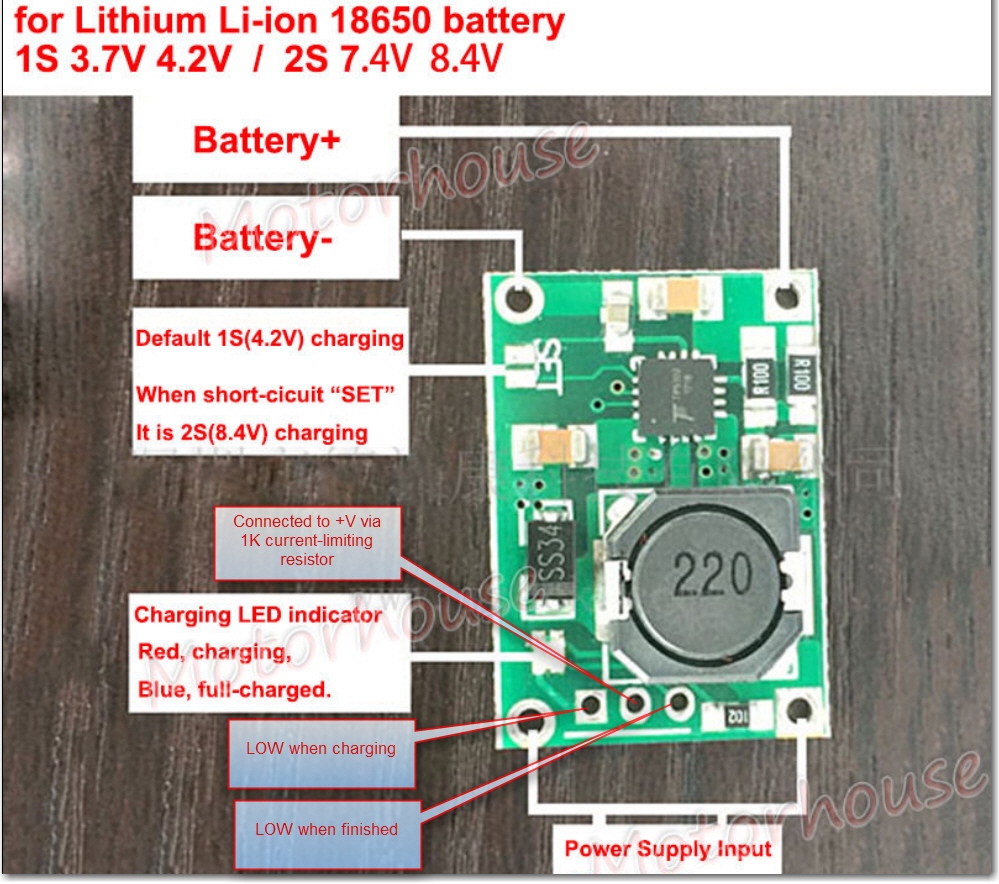
  • There is an onboard Red/Blue LED and solder holes for an external bi-color LED.   The onboard LED states are:
    • RED = Charging
    • Blue = Finished
  • Both the onboard and external LED connections are tied to +V via the same 1K current limiting resistor.   This resistor is routed to the center hole of the 3-hole external LED breakout.   The rightmost hole is tied to an open-collector gate that goes LOW upon charge termination, and the leftmost hole is  tied to an open-collector gate that goes LOW upon charge initiation.   In my testing circuit above, these lines are labelled ‘Fin’ and ‘Chg’ respectively and were routed to digital inputs with 20K pullups on the Arduino UNO.
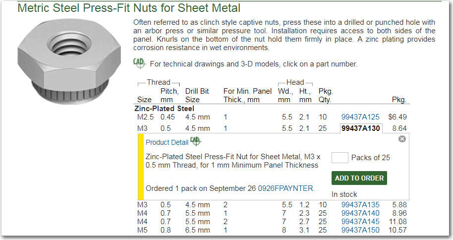
  • This is  NOT a balance charger – so there may be differences in cell voltages over time.   If this is a potential issue, then separate cell protection modules like these should be installed.

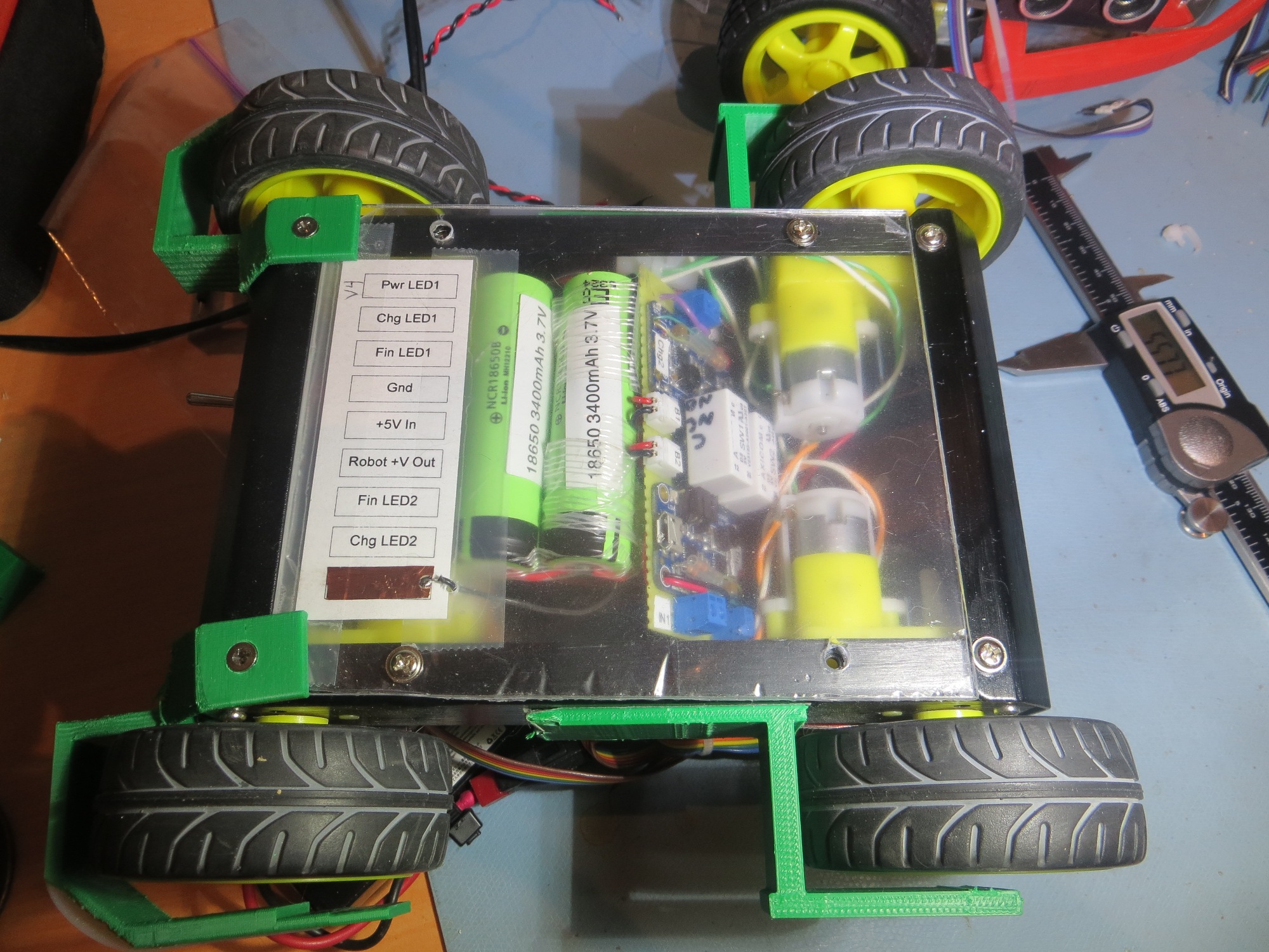
Here’s an annotated photo showing the pertinent features:

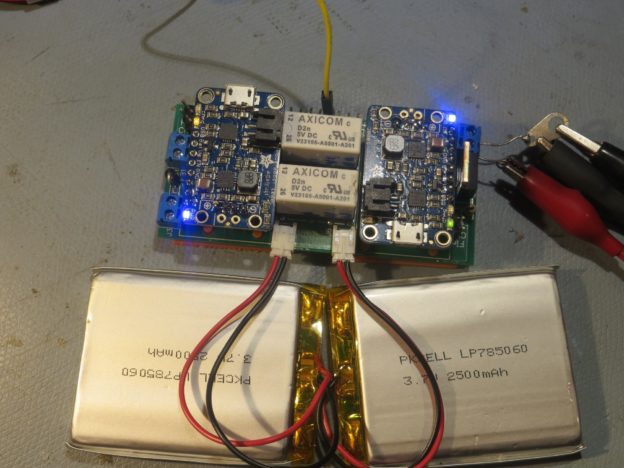
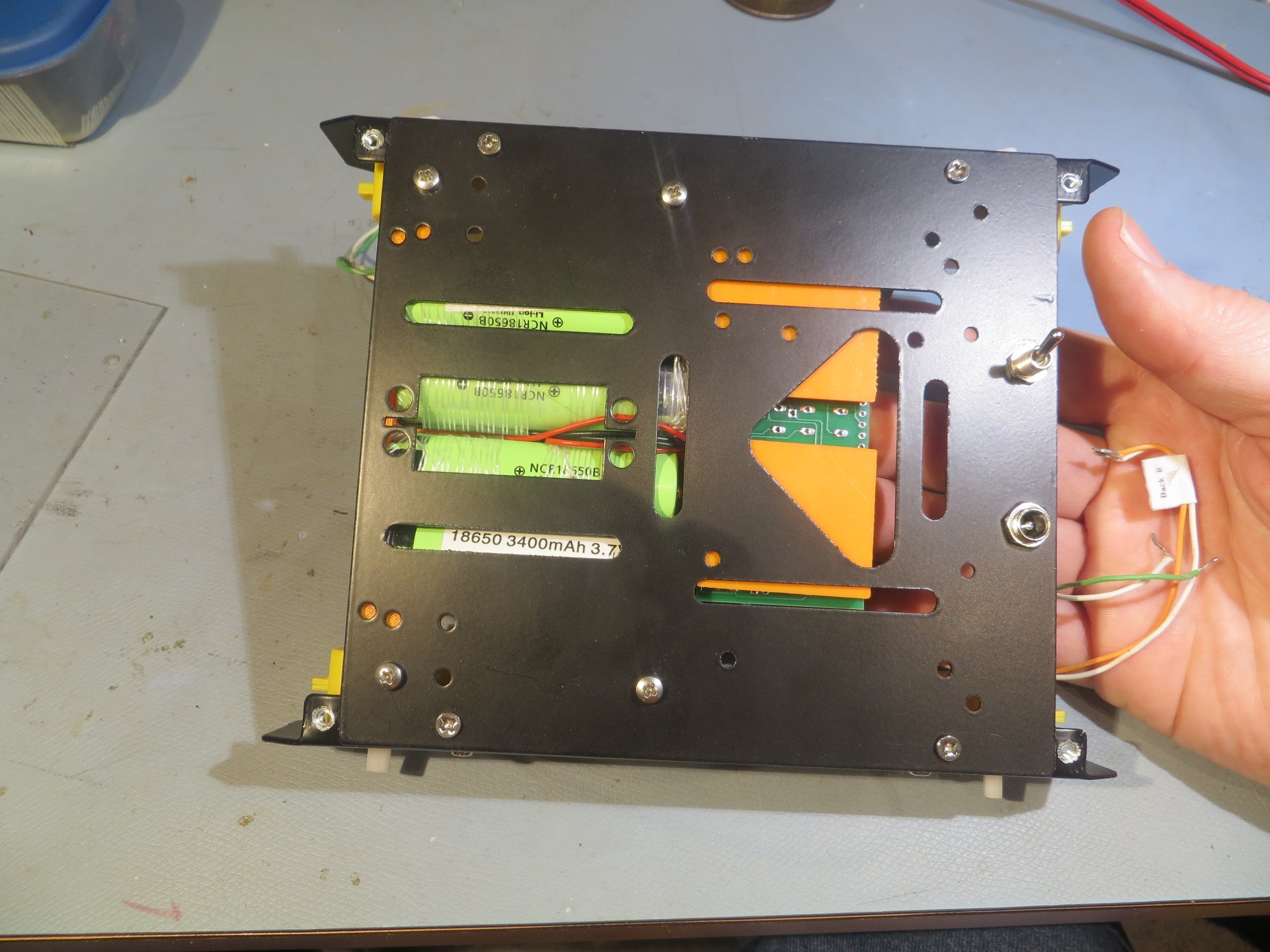
So, it looks like this TP5100 module will work fine for my 2-cell LiPo application, with the addition of an external 2-cell protection module like the one noted above.   Not only will this solve my original IR drop problem, but it is  much smaller and simpler too, as shown in the following size comparison shot.   Oh well, at least I had a lot of fun building up and testing the original charger module ;-).

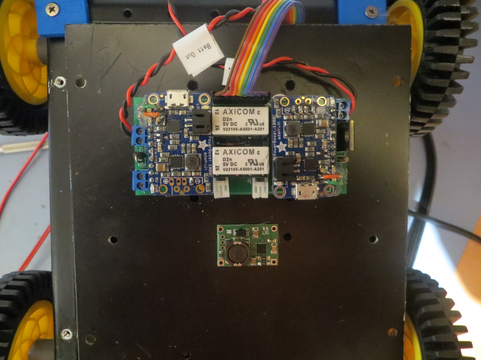
charger module and TP5100 size comparison

Stay tuned!

Frank


The operation was a success, but …

Posted 21 February 2018

In early January of this year I posted about finishing the integration of my new-improved battery charger & battery pack into my new-improved robot chassis.   Between then and now I have been working on getting the new robot chassis mated up with the charging station (the new robot chassis is wider, and I also changed to larger diameter wheels) in preparation for renewed field testing.

Unfortunately, just as I was getting ready to move into field testing, my robot started acting funny.   About half the time, it wouldn’t disengage from the charging station and instead would reboot.   At first I thought the added weight of the new battery pack and robot chassis was causing the motors to stall, so I changed the code to have the robot disconnect at full motor speed rather than 1/2 as before.   This made the problem even worse; now not only wouldn’t Wall-E2 disengage from the charger, it wouldn’t even move forward or backward under it’s own power!   Clearly something was badly wrong, but I had no clue what it was.

Applying my time-honored troubleshooting – I simply put Wall-E2 aside for a few days and let my subconscious work backwards through all the changes since Wall-E2 had last worked properly.   After enough time had elapsed, my subconscious reported back and said:

“You are an idiot.   All of the complexity you added in your quest for an on-board charging system has placed that wonderful high-capacity battery pack at the far end of a long series of (relatively) high resistance circuitry, and the IR drop caused by full-speed motor currents is killing you!”   “Oh, and by the way, you’re ugly too!”

Well, my subconscious is almost never wrong, and it only took me a little bit of testing to confirm it’s theory.   I set the code up to go forward and backward at full speed, and monitored the CPU’s 5V regulated output line with my trusty oscilloscope.   As soon as the motor command was executed, the 5V line drooped to less than 3V, and the CPU rebooted – oops!

So now I knew  what was happening, and I (or my subconscious anyway) had a good idea  why.   To confirm the why, I bypassed all the charge-management circuitry and wired my 7.4V 7200mAh battery pack directly into the main robot power line, as shown in the photo below

7.4V 7200mAh battery pack wired directly into robot power

With this setup, the robot not only was able to move forward and backward at full speed, the thing damn near took my arm off when I tried to stop it – whoa!

So, the bottom line is that all the work I put in designing and implementing a really cool on-board dual-cell charge management system had the ultimate effect of making the battery unusable.   The operation was a success, but the patient died! ;-).

So, where to go from here?   It appears that I have to completely revise my thinking about battery charging and maintenance for Wall-E2.   Instead of being in series with the battery, any charging/maintenance system must operate in parallel, and be completely out of the path between the battery pack and the load when the robot is running.   Now I realize this is the reason most RC/Hobbyist multi-cell battery packs have a balance charging cable in addition to the main power cable; charging is done completely independently of the output path.

When I first started the charger project, my original goal was to avoid having to remove the battery from the robot to charge it; I wanted Wall-E2 to   connect to power and charge itself without human intervention.   At the time, I felt the only way to do this was to have the charging circuitry on board, so that only a single DC connection from the charging station was required.   I thought the only way to make this happen was to use two of the Adafruit SBC1000 charger modules to charge each of the two cells independently.   Unfortunately, the SBC1000’s grounds aren’t isolated, so this meant that I had to disconnect the two battery pack cells from each other to charge them independently and then switch them back together again to run the robot after charging.   This worked (rather elegantly if I do say so myself), but had the unintended side-effect of putting too much high-loss circuitry and wiring between the battery pack and the motors.

Now that it is clear that I can’t interfere with the current path to the motors, I know I have to abandon the current charging module design, but what are the alternatives?

  • The TP5100 is a little module that can balance charge a 2-cell LiPo stack at 2A.   It has a dual-color LED output that I might be able to use for charge termination.   Unfortunately, the specs are all in Chinese, so it may take some experimentation to figure out.
  • I can use an external balance charger like the EV Peak e4 ‘cube’ automatic balance charger, and feed the three required wires (ground, B1+, B2+) out through the front of the robot to the charging station. This solves the problem of carrying the charger around, but significantly complicates the interface to the charging station.

Stay tuned!


Printing an ABS Shaft Adaptor for 80mm Wheel

Posted 25 January 2018

Over the last few days I have been struggling with a project to 3D print a small adaptor to allow me to mount some 80mm wheels I bought some time ago to my Wall-E2 autonomous wall-following 4-wheel drive robot.

The original robot came with 56mm wheels and this gave Wall-E2 very little ground clearance.   I found some 80mm wheels that I thought would do the trick nicely, but when I tried them, it quickly became apparent that the shaft receptacle on the wheel was significantly larger than the motor shaft, leading to a very bad wobble and catastrophic wheel departures – oops!

Lightweight 4WD Drive Aluminum Mobile Dolly Car Robot Platform for Arduino


original 56mm wheel and companion motor

Ebay ‘Arduino Robot’ motor dimensions

80mm wheel

After some troubleshooting, I discovered that the new 80mm wheels have a shaft receptacle that measures 5.9mm long and 3.6mm wide, while the motor shafts are 5.4mm long and 3.5mm wide.   The width is OK, but the longer length is causing the problem.

After thinking (and cursing) a bit, I decided to try printing an adaptor.   The larger diameter wheels are also considerably thinner (20mm or so vs 30mm), so there should be room for an adaptor part, as shown below

shaft adaptor for 80mm wheel

And threw it on my PowerSpec 3D PRO (Flashforge Creator Pro knockoff).   After just a little fiddling, I got some nice parts, and thought I was done.   A couple of days later, I noticed one of the parts was just a little loose on its shaft, so I said to myself – “I’ll just print off another one”.   Unfortunately, what came off the printer was really ugly, and completely unusable, even though that same printer had produced nice parts just a few days ago – WTF!?   Clearly I had forgotten what magic I had wrought the first time, so now I had to go back and recreate it – bummer.   As part of my penance for this crime, I am writing this post so the next time I want to do this, I’ll have the print settings recorded.

Print Settings for ABS

The significant factors in how to get good prints with ABS on this printer appear to be

  • Print speed
  • Extrusion factor

The first thing I did was slow the print speed down, but this had only a minor effect on print quality.   Going slower helped, but even very slow speeds (like 10mm/sec) didn’t result in clean edges on the male part of the adapter. However, the female portion was very clean, which left me a bit puzzled – why one part but not the other?   I finally realized that the difference was that the female piece was perfect because the hole perimeter was the first thing laid down at each slice, then the outside perimeter, and finally the fill material was added last.   This meant that the hole perimeter had a chance to cool and solidify before the fill material impinged on its outer surface, and this meant that the perimeter stayed in the same shape as originally laid down.   When printing the male part, however, the outer perimeter was laid down first, and then the fill material was immediately added, before the outer perimeter had a chance to cool and solidify, even at the slower speeds.   The material making up the fill was pushing the outer perimeter out of shape.

This led me to focus on the extrusion factor.   Reducing the extrusion factor from 1.00 to 0.95 had a significant positive impact on the print quality of the male portion of the adaptor.   Reducing it again to 0.90 resulted in an even better print, as did a further reduction to 0.85.   However, at the 0.85 value, I started to see some degradation in the quality of the female portion, so I backed off to 0.90 as the final value.   The following image shows the last seven prints.   All were printed at either 20mm/sec or 10mm/sec, and the last three on the right were printed with 10mm/sec and extrusion factors of 0.95, 0.90, and 0.85 respectively.

The last seven prints. the last three on the right were printed at 10mm/sec and with extrusion factors of 0.95, 0.90, and 0.85 respectively

Original and new wheels, with completed adaptor shown

Bottom Line (PowerSpec 3D Pro, Simplify3D):

  • Material: Gray ABS
  • Extruder temp: 230 (not critical 220-240 should be OK)
  • Bed temp: 110 (not critical, 100 should do too)
  • Speed: 20 or 10mm/sec (maybe faster would be OK, but not much)
  • Extrusion factor: 0.95 or 0.90


Wall-E2 battery charger module integration

Posted 01 January 2018

What a way to start off the new year!   The battery charger module for my autonomous wall-following robot Wall-E2 has been completed and tested, and now has been integrated into the robot – yay!!

If you have been following this saga, you will recall that I started working on an internal charging module for Wall-E2 well over a year ago, back in November 2016 with this post.   Since then I have gone through several iterations, revisions, and mis-steps (including a semi mind-boggling deep-dive into the details of the Adafruit PowerBoost 1000C specifications in this post).   Last month I finally got a complete system (two PowerBoost 1000C’s integrated onto a single PCB with appropriate control and battery switching circuitry) working, and was able to run extensive charge/discharge cycle testing using a simple test circuit and an Arduino Uno to run it. So, now all I had to do was stuff the whole thing back into the robot.   This task was made possible by my earlier decision to upgrade Wall-E2’s ride to a slightly larger chassis, so instead of trying to cram 2Kg of battery/charger into a 1Kg space, I now had the pleasure of fitting 2Kg into a 3Kg space – nice!    Here are some photos of the integration process.

Battery module shown in the ‘maintenance’ configuration.

Another shot of Battery module in the ‘maintenance’ configuration.

Front cover removed to show how the battery module fits into the robot. Note there is plenty of room for cable runs

Front cover removed to show how the battery module fits into the robot. Note there is plenty of room for cable runs

Rear cover removed to show how the battery module fits into the robot. Note there is plenty of room for cable runs

Rear cover removed to show how the battery module fits into the robot. Note there is plenty of room for cable runs

Now that the battery/charger module has been integrated into the robot chassis, I will have to make some minor changes to the robot operating system to accommodate changes I have made along the way, but these should be easy and straightforward.   Then, it will be back to field testing, I hope.

Stay tuned!

Frank


Wall-E2 battery charger module testing, Part II

Posted 22 December 2017

After having worked out (hopefully) all the bugs in the Arduino Uno program and associated test hardware, I have moved on from testing just one of the Adafruit PowerBoost 1000C   charging module in isolation to testing the entire 2-cell battery pack system, albeit with the smaller 2500mAh LiPo’s rather than the full-up 18650 stacks.

Full-up test of the 2-cell charging system using 2500mAh LiPo cells

Full charge of 2500mAh cells

After several days of testing, I never really got consistent results with this setup – I seemed to be always chasing intermittent problems of one sort or another.   Then I finally figured it out (I think) – the problem wasn’t my setup, it was the proto plug-board I was using.   This board was a cheap no-name plugboard I got off eBay, and apparently I got exactly what I paid for! ;-(.   So, I reverted to my tried-and-true (but HUGE!) AP Products A.C.E. 236 plugboard that I have had around the lab for a couple of decades, at least.   When I transferred the setup to this plugboard, everything started working better.   In particular, the battery charging current went from about 0.5A to about 1.5A – a much more believable (and practical) figure than before.   Here’s the new test setup.

New test setup with my trusty AP ACE 236 plugboard. Note charging current shown on current meter

After getting the hardware problems squared away, I started getting reliable charge/discharge cycle data, as shown in the curves below

Two complete charge/discharge cycles. Note the time axis is in minutes here

The next step in the process will be to replace the PKCell 2500mAh flat-pack LiPo cells with the 6800mAh pack (two series banks of 2ea Panasonic 18650 3400mAh cells in parallel) to be used in the robot.

26 December Update:

Chg/Dischg testing with the Panasonic 18650 packs from the robot.

As shown above, I switched out the 2500 mAh flatpacks for the Panasonic 3400 mAh cells from the Wall-E2 robot.   Initially I was somewhat disappointed with charging performance, as I was only seeing about 1 – 1.5A initial charge current for both 6800 mAh cells, instead of the 2+ A I expected to see.   Eventually I narrowed the problem down to stray resistance in the testing circuit itself, through the plugboard, the plugboard wiring, and the relay being used to switch charging power to the battery module.   When I bypassed these elements and connected the external MeanWell 5V power supply to the battery module terminals, the max current increased to slightly over 2A, as expected.   This is actually very good news, as it means that the resistance of the PCB traces supplying power to the PowerBoost 1000C modules is low enough to not materially affect the max charging current – yay!

Still, even with the max charging current up at 1A/cell and with the PB 1000C’s PROG3 charge termination resistor reduced from 100K to 33K, it takes every bit of 10 hours to charge the battery pack from 3V to 4.2V, as shown below.

Panasonic 18650 6.8AH robot battery pack. Initial charge rate approx 1A per 2-cell parallel stack

Panasonic 18650 6.8AH robot battery pack discharge, 15 ohm load

28 December 2017 Update:

While testing these battery packs for charge and discharge performance, I came to realize that I had over-complicated the test circuit.   The original test circuit is shown below:

This circuit uses a relay to switch +5V power to the charger modules in the battery pack module, and also to switch the load in and out.   As I gained more experience, I realized the relay contact resistance was substantially reducing the charge current, so I wired +5V directly to the battery pack; this worked because the Arduino running the test circuit keeps the battery pack parallel/series relay disengaged (meaning the battery cells are arranged in series) until the load voltage drops below a set threshold.   So, this realization resulted in the following updated circuit schematic.

As shown above, I added the connections to the battery charger module, and the LED displays.

However, I have now come to realize that the other half of the relay isn’t necessary either, as the ‘Robot +’ line isn’t connected to anything until the test manager computer (Arduino Uno) recognizes the end-of-charge condition and changes the Coil Enable signal from HIGH to LOW, disabling the battery pack’s internal relay and changing the battery configuration from parallel (CHARGE) to series (RUN).   So, now the test circuit can be reduced to just the LEDs and the load resistors, as shown below.

While I was making the other changes, I also cut the load resistance in half, from 15Ω to 7.5Ω to more accurately simulate the actual robot motor loads, and (finally!) managed to capture a complete discharge cycle, as shown below.

Complete Robot Battery Pack Discharge Curve, 7.5-ohm load.

The 7.5Ω load for this run provides a good approximation for the maximum current drain experienced by the robot under most operating conditions, so it is now safe to say that the robot should be able to run at least 6 hours on a charge, and that a full charge will take about 10 hours.   So, the robot will spend more time on the charger than on the road, but that’s life in the robot lane.

Stay tuned!

Frank


Wall-E2 battery charger module testing, Part I

Posted 15 December 2017

For the last couple of months I have been working on the battery subsystem for my Wall-E2 autonomous wall-following robot.   Along the way I upgraded the robot chassis to provide more room for the on-board charger & battery pack, and created a PC board design for the module that charges the 2-cell LiPo stack in parallel and then switches to a serial configuration to run the motor.   This post describes the first part of a testing program to validate the performance of the Adafruit PowerBoost 1000C charger module, and the idea of switching seamlessly from charging to powering a load.

By way of background for this post, I ran into some difficulties when I tried to integrate the full-up 2-cell, 2-PB1000C battery pack/charger combination into my Wall-E2 robot, and troubleshooting the problems using the complete operating system software proved to be somewhat tedious, I decided to start at the other end with a very simple test program running on an Arduino Uno, and a single PB1000C charger.

The Arduino test program is very simple; when it is initialized, it checks the battery voltage to see if is above or below a preset threshold.   If above, it energizes a DPDT relay to connect the battery to a 15Ω load; if below, it de-energizes the relay, which disconnects the battery from the load and also connects 5V to the ‘USB’ (5V input) terminal of the PB1000C, thereby charging the battery.   After that, the program alternately switches the battery between the load and charging states, recording the battery voltage every four seconds.

Battery Testing Hardware

Arduino Uno and test circuit.   Note the yellow ‘charging’ LED on PowerBoost 1000C shown at middle right

After working the inevitable bugs out of the Arduino program, I got some reasonable battery cycling data, as shown in the following plots.   The battery used in all these tests was a PKCell LP795060 LiPo cell, rated for 3.7V and 2500mAH.   It is rated for about 5hrs at 0.2C discharge, but I was only seeing about 3hrs at 0.1C, most probably because I was terminating the discharge at 3.4V rather than the 2.75V used in the discharge tests.

Two complete chg/discharge cycles

Chg/Dischg cycles using PB2 (same battery as previous tests). Short cycles may imply battery wear-out

After the last test above, I was concerned that either the PowerBoost 1000C was not operating properly, or the battery itself was failing, or both.   So, I changed the discharge termination threshold from 3.4 to 3.0V to be more consistent with the 2.75V cutoff used by the battery manufacturer.   After making this change only, I got the following plot

Charge/discharge cycles after changing the discharge termination threshold from 3.4 to 3.0V

As can be seen from the above plot, the discharge and charge times were extended dramatically.   Discharge (at approximately 220 mA or 0.1C) took well over 3hrs, and charge took about the same amount of time.   So, it appears that both the PowerBoost 1000C modules are still working OK even after the abuse I put them through by plugging them into a PCB with wiring errors ;-).


Wall-E2 Battery Charger PCB Part II

Posted 1 November 2017

In my last post on this subject, I described my efforts to create a PCB for the charging module in my wall-following robot(s).   I showed the hand-wired original, and the first (of three, so far) PCB versions. My circuit-checking skills are a bit deficient, so I keep finding ‘issues’ with the PCBs I received from Bay Area Circuits.   It’s not their fault as they produced PCB’s  exactly like I told them – apparently they don’t know about the RDM (Read Designer’s Mind) checkbox on their order form! 😉

In any case, the major problems I discovered on the first two revs are, kind-of, understandable for a PCB newbie like myself; I had the JST battery connectors switched, so Batt+ showed up on the PCB as Batt-, and the IRF-510 transistor holes were reversed as well.   A bit of cut-and-jumper work solved the first problem, and simply turning the transistor around solved the second one.   However, I really didn’t like leaving that as the ‘final solution’ so I splurged another $30 on a third rev with these problems fixed.   These boards have not yet arrived, so in the meantime I continued testing on the current setup.

As the photo below shows, the finished and populated PCB has almost exactly the same dimensions as the hand-wired perfboard model.   Since the perfboard version had several components mounted on the wiring side, arriving at the same dimensions with everything on  one side is a definite plus!

comparison between the hand-wired perfboard version and the PCB

After getting the PCB populated, I did some electrical testing, and somewhere along the way I think I managed to damage the boost regulator chip on one of the PowerBoost 1000C modules.   And this is where I discovered my  next  major booboo – I had hard-wired the PB1000C’s to the PCB, and so now I couldn’t replace the damaged part without destroying the part, and probably the PCB too – oops!

07 December 2017 (Pearl Harbor Day) Update:

I received the latest (and hopefully, last!) batch of battery charger module PCB’s from Bay Area Circuits a week ago, but have been too busy with other things (mostly dealing with the new V3 robot chassis) to do much with it. So, today I started populating and testing the new charger module.   As I mentioned before, one of the bigger mistakes I made on the previous version was to hard-wire the PowerBoost 1000C’s onto the PCB, making it almost impossible to replace if it failed (and, as I learned from the Adafruit forums they can be easily damaged if they are powered up without a battery attached).   So, this time I soldered female headers onto the PCB and male headers onto the charger modules, making them easy to replace if needed.

New charger module with some test batteries attached

Charger module showing PowerBoost 1000C header arrangement

The next step will be to test the module’s ability to manage the robot’s battery stack.   I plan to simulate the robot load with a 500 mA resistive load, and simulate the actual battery stack with the two smaller 2500 mAH batteries shown in the above photos.   I’ll simulate the robot with an Arduino, programmed to print out time-stamped readings of the robot power voltage (actually 1/3 of the robot power voltage, but what’s a scaling factor between friends?).

Stay tuned!


A New Chassis For Wall-E2, Part II

Posted 17 November 2017

In my ongoing quest to give Wall-E2 a bigger/roomier ride, I am continuing the process of moving all Wall-E2’s stuff to the new chassis, and modifying the charging station to work properly with the new wide-body model.

Second Deck Sensors:

Even with the wider footprint, there’s not enough real estate to easily mount the three distance sensors (LIDAR for forward distance, and acoustic for left/right distance).   I could shoe-horn it all in, but it would look messy and would leave all Wall-E2’s electronics exposed to potential damage from furniture, cats, careless humans, etc.   So I decided to transplant the second deck, complete with all the sensors, to the new chassis.   This looked to be a real PITA, until I let go of the notion that the 60mm stand-offs had to remain in the same locations. Once I did that, things got a  lot easier 😉

IR Homing Module:

This was a straightforward transplant, especially since all the detection/demodulation is being

3D printed spacers for the motor controller PCBs

done by a Teensy 3.2 physically attached to the sunshade. All I had to do was drill the mounting   holes, add two more press-fit nuts, and screw on the module.

Arduino Mega Processor and Motor Controllers:

These two items came over as a group, as that way I didn’t have to disconnect anything – my kind of transplant!   However, while I was at it, I decided to neaten things up a bit by printing spacers for the motor controllers; this isolates the underside of the PCBs from the metal chassis, and provides a nice flat surface for mounting the controllers to the chassis with double-sided tape – a win-win-win (the last ‘win’ was because I got to use my 3D printer some more!)

Arduino Mega processor, motor controllers, rear taillight assembly, and IR homing module transplanted

Charging Station Modifications:

I was  not  looking forward to modifying the charging station to work with the new wider chassis.   The charging station electronics assembly is non-trivial, and it would be a real PITA If I had to reprint the frame and transfer all the electronics. Fortunately for me, this turned out not to be the case.    By a happy coincidence, the distance from the right-hand guide rail to the center of the power receptacle was exactly the same for the new chassis as for the old one, so all I had to do was re-position the left-hand rail to accommodate the wider tread spacing. Well, there was one minor glitch – the charging station has two physical stops, and the one that mated with the left-hand wheel guard on the old chassis now didn’t hit anything, so I had to print a small 5mm thick spacer and double-sided tape it to the front of the existing stop.

Closeup of the spacer for the right-hand charging station stop

Front view showing left and right charging station stops (with spacer added to right one)

18 November 2017 Update:

I’ve got almost everything transplanted over now, as shown in the following photos:

Side view without the sensor deck, showing that all modules are in place

Side view showing the sensor deck in place.

end-on view showing the difference between the old and new chassis dimensions

There’s still a ton of work to be done; The latest version of the charger PCB still hasn’t arrived from Bay Area Circuits, so I still need to do all that, and then wire the finished module into the battery compartment. Also, I’m having to redo the front bumper guards, as I have found they are somewhat fragile due to the way in which they were printed – bummer!   However, it shouldn’t be  too long before I can take the new model out for a spin! ;-).

Stay tuned!

Frank


A New Chassis For Wall-E2, Part I

Posted 06 November 2017

Back in May of this year I came to the conclusion that I was never going to get my new four-cell battery pack (4ea 18650 3600mAH 3.7V LiPo cells connected as 2ea 7400mAH 3.7V stacks) and its companion charger module to comfortably fit into Wall-E2’s current chassis.   It all fits, but only with a considerable amount of pushing and shoving which has invariably resulted in damage to something – a connector, a wire, or something else vital.

Bottom side view of 4WD robot showing battery packs and charging module

Bottom rear view of 4WD robot showing battery packs and charging module

So, I spent some quality time online looking for a new, larger home for Wall-E2, and found this chassis

Lightweight 4WD Drive Aluminum Mobile Dolly Car Robot Platform for Arduino

This chassis has an internal cavity width of about 14cm compared to 10.5cm for Wall-E2’s current ride.   This extra inch or so make all the difference in the world for comfortable installation of the battery pack and charger.

After getting this chassis on order, I basically forgot about it while I was working on the square-wave modulated IR homing project.   Then when my grandson Danny and his family visited in August, we dug out the kit and assembled it.   Danny wasn’t all that impressed with the quality (well, neither was I, but I didn’t expect all that much for $30 either).   After looking at both chassis (Wall-E2’s current ride and the new one), Danny suggested that maybe we could transplant the motors from the new chassis into the old one and get enough additional space from the different form factors to solve the battery problem.   At the time I pooh-poohed the idea, and put the new chassis back on the shelf to be forgotten again.

However, after finishing up the IR homing project last month, I decided I would actually try this trick and see what happened.   So, I laboriously swapped all four right-angle motors from the new chassis to the old one, and … RATS!!   As the photos below show, no real change in the available room for the charger/battery pack combination.   Well, at least I tried ;-).

So, now I’m back to swapping chassis (wow – plural form of ‘chassis’ is ‘chassis’ – go figure) instead of motors.

One of the major shortcomings in the new model was the cheapness of the threaded holes in the frame components.   The frame metal is so thin that instead of drilling and tapping the material, the holes were punched in a way that left the punched-out metal in the hole, and this material was tapped with the machine thread.   Needless to say, this lasted for about one (or fewer) screw/unscrew cycle before stripping out – bad design!.   Fortunately I knew how to fix this problem, with the help of McMaster-Carr.   I went to their site and ordered a bunch of press-fit nuts (also called PEM-nuts for historical reasons)

Press-fit nuts for my new robot chassis

In case you have never dealt with McMaster-Carr, they are incredibly quick.   I normally tell people that once I click on the ‘order’ button, I get up, walk to my front door, open it, and get hit in the chest by the shipped order! ;-).

Once I got the nuts, I replaced all the threaded holes on the new chassis with these wonderful little gadgets.   I used a #16 number drill to drill out the holes, and pressed the nuts in the new holes with a pair of cheap gas pliers – done!

As seen below, there is a  lot more room in the new model

In fact, there is so much room that now I have to figure out how to keep the batteries and charging module from sloshing around in there.   Fortunately I have a fertile imagination, TinkerCad, and a 3D printer – so I designed and printed up a battery box, and a prototype stand-off design for the PCB, as shown below.

The next part of the puzzle will be to figure out how all that stuff (IR Homing Module, laser and ultra-sonic distance sensors, motor controllers and the main controller) is going to fit on the new chassis.

Stay tuned!

Frank


Adafruit PowerBoost 1000C Charge Termination Threshold

Posted 01 November 2017

At the conclusion of my ‘field’ testing of Wall-E2’s new-found ability to mate with the charging station using the square-wave modulated beacon signal, I noticed that Wall-E2 was always disconnecting from the charging station based on elapsed time (set for 2Hrs at the moment) rather than detection of the end-of-charge condition.   After investigating this a bit more, I found that one of the charging modules never switched from charging to ‘finished’.   This was more than a little irritating, as I was counting on that transition to make sure that Wall-E2 was fully charged before disconnecting.

During the process of creating the PCB design for my charging module, I took a dive into the datasheet for the MCP73871 charge management chip on the PB1000C in an effort to figure out if there was any way to improve the end-of-charge detection situation.   When I looked through the specs (relevant data sheet portions shown below), I found that there is a spec called ‘Charge Termination Ratio’ (oddly shown with dimensions of mA, but what do I know), and this value is controlled by the value of the resistor connected to the PROG3 pin.

On the Adafruit PowerBoost 1000C module, the resistor attached to PROG3 is 100K, the larger of the two values mentioned in the datasheet, and this value sets the charge termination threshold at approximately 12.5 mA (according to the Adafruit gurus, ‘approximately here means +/- 25% – yikes!)

So, I decided to see if decreasing the value of this resistor give me a more robust charge termination experience.   Rather than trying to replace the SMT/SMD resistor part, I decided I could just mount a regular 1/8W resistor in parallel, with the value chosen to get the right resultant value.   Since there is such a large (+/- 25%) variation, there’s no real good reason for trying to arrive at an exact value, so I just chose a convenient value (meaning the closest value I could find in a small 1/8W package) – in this case, 51K.   With a little bit of patience, and a strong magnifier, I was able to get the resistor soldered onto the SMD part without burning up the pads or anything else, as shown in the following photo

51K resistor soldered in parallel with the existing 100K resistor on the MCP73871 PROGR3 pin

This parallel combination results in an PROG3 resistor value of about 33K, which (assuming a linear progression) should result in a charge termination current of about 40mA.   When I tried this setup with a mostly charged battery and an Adafruit ‘Charger Doctor’ for monitoring charge current, the PB1000C changed to the ‘finished’ state with a measured current of about 20mA.

When I first tried this trick, I was expecting the charge to terminate when the Charge Doctor readout showed “0.04” – but it didn’t happen until more like “0.02”.   When I mentioned this on the Adafruit forum, a very knowlegeable reply was forthcoming from “Mike”

Re: Powerboost 1000C Charge termination threshold

by  adafruit_support_mike  on Tue Oct 31, 2017 9:54 am

“Charge termination ratio” is a general term for LiPo chargers. Most of them don’t use an external resistor to set the cutoff current, and just end the charge cycle when the current flowing into the battery reaches a given fraction of the constant-current level.. 1% is fairly common.

If you run the math out, the ratio of I.prog:I.term is R.prog1:R.prog3

We started with 100k because that’s one of the two values listed in the DC Characteristics table, and after a while you learn to take datasheets very literally. They excel at telling you the parts of the truth the vendor wants you to hear, but nothing more. It’s always best to start from the exact spec values and then vary the parameters to see what they left out.

We left it at 100k because it worked, and the datasheets for the LiPos we carry spec 1% as the termination level.

The tolerance for that value is +/-25%, so a nominal value of 33mA can be expected to fall in the range between 24.75mA and 41.25mA. The Charge Doctor has a resolution of 10mV/10mA, and I’d expect its measurement error to be about half that through rounding if nothing else. That puts the potential range of measured values for a nominal 33mA current between 19.75mA (rounded to 20mA) and 46.25mA (rounded to 40mA).

The error is almost as large as the value you want to measure, and larger than the difference you want to measure.

 So I thought about that some more, and eventually realized that the cause of my non-termination woes might well be that I’m using these chargers on much larger (capacity-wise) cell stacks than normal.   I’m using a 7400 mA stack, so a 1% threshold would be 7.4mA, which may be a little too close for comfort to the 12.5 mA termination spec for a 100K resistor on PROG3.
In any case, this exercise taught me a  lot more about the PowerBoost 1000C in general, and the MCP73871 chip specifically.
Stay tuned,
Frank