Tag Archives: magnetometer

Giving Wall-E2 A Sense of Direction, Part X

Posted 15 August 2016

In my last post on this subject, I described a series of ‘field’ tests of the magnetometer on Wall-E2, my wall-following robot.  These tests demonstrated that the magnetometer was operating properly, but heading results were unusable due to significant distortion of the magnetic field along the west (garage-side) wall of the entry hallway.

This post describes a similar test in an interior hallway. The interior hallway in our home is oriented orthogonally to the entry hallway, i.e. at 110/290 deg magnetic. The walls are about 1 m wide, and constructed of standard wooden stud and sheet rock construction.  There are several rooms opening off this hallway, but all the entry doors were closed for this test.

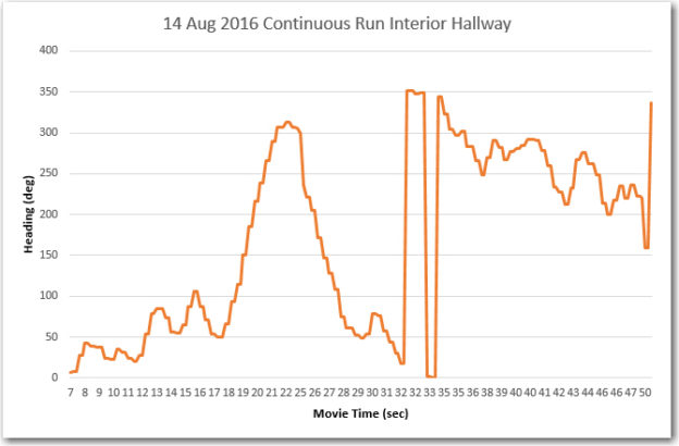
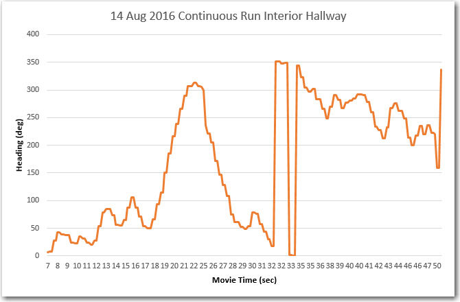
As shown in the movie and the associated Excel chart, the robot starts at the west end headed east, travels the length of the hallway, maneuvers around for a while, and finishes up headed west.  During the first and last 10-15 seconds of the run, Wall-E2 is physically heading in a more or less constant direction (about 110 deg in the first part, about 290 deg in the last part).

Wall-E2 heading results from interior hallway run

Wall-E2 heading results from interior hallway run

Unfortunately, the Excel chart shows a different story.  During the first 15 seconds of the run, there is a definite linear change in the average heading, from about 25 deg to about 75 deg, even though the robot is physically tracking along a wall that is oriented at about 110/290 deg.  During the last 15 seconds or so, the opposite happens; there is a linear downward trend from about 300 deg to about 225 deg.   These trends are physically impossible, so the only possible explanation is that either the magnetometer readings are in error, or there is something in or near the interior hallway that is distorting the earth’s magnetic field enough to produce these results.

I had hoped that the interference noted in the previous post was due to the common wall with the garage and its associated metal structures,  and that the interior hallway would be free of such problems, but apparently this is not the case.  So, I’m now forced to consider other ideas for interior geo-location.

Stay tuned!

Frank

Giving Wall-E2 A Sense of Direction, Part IX

Posted 12 August 2016

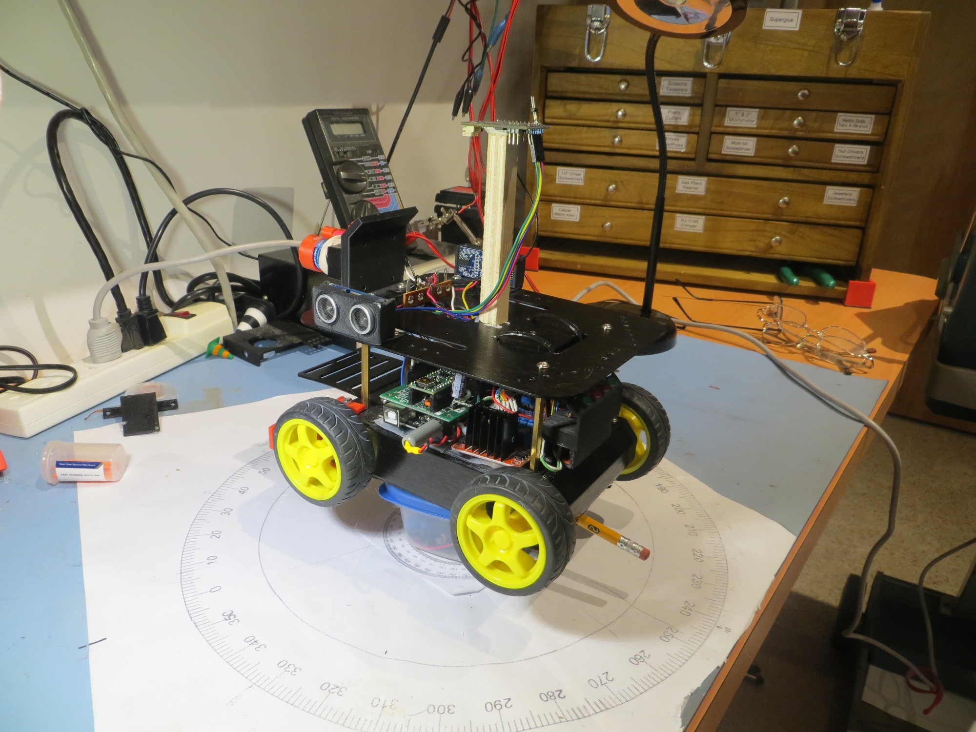
For the last several months (or was it years – hard to tell anymore) I have been trying to implement a magnetic heading sensor for Wall-E2, my wall-following robot.  What started out last March as “an easy mod” has now turned into a Sisyphean ordeal – every time I think I have one problem figured out, another (bigger) one pops up to ruin my day.  The first problem was to  re-familiarize myself with the CK Devices ‘Mongoose’ IMU, and get it installed on the robot.  The next one was to figure out why it didn’t work quite the way I thought it should, only to discover that sensitive magnetometers don’t really appreciate being installed millimeters away from dc motor magnets – oops!  So, that little problem led me into the world of in-situ magnetometer calibration, which resulted in my creation of a complete 3D magnetometer calibration utility  based on a MATLAB routine (the tool uses Windows WPF for 3D visualization, and Octave for the MATLAB calculations – see this post).  After getting the calibration tool squared away, I used it to calibrate the Mongoose unit (now relocated to Wall-E2’s top deck, well away from the motors), and once again I thought I was home free.  Unfortunately, reality intruded again when my ‘field testing’ (in the entry hallway of my home) revealed that there were places in the hallway where the  magnetometer-based magnetic heading reports were wildly different than the actual physical robot orientation, as reported in my July post on this subject.

After the July tests, I knew something was badly wrong, but I didn’t have a clue what it was, so I decided to put the problem down for a while and let my subconscious poke at it for a while.  In the interim I had a wonderful time with my two grandchildren (ages 13 & 15)  and a real 3D printing geek-fest with the younger of the two.  I also got involved in creating a small audio amplifier in support of the Engineering Outreach program here at ‘The’ Ohio State University.

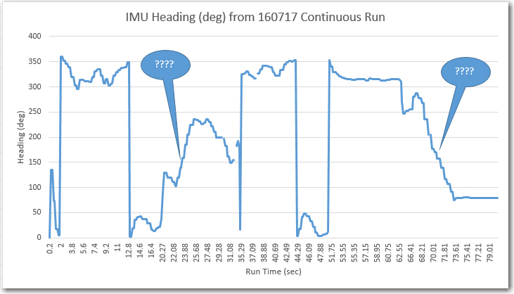
So now, after almost a month off, I’m back on the case again, trying to make sense of that clearly erroneous (or at least non-understandable) data, as shown below (repeated from my previous post)

July continuous run test, showing two areas where the reported headings don't match reality

July continuous run test, showing two areas where the reported headings don’t match reality

The two areas marked with ‘???’ correspond to the times where the robot was traversing along the west (garage side) wall of the entry hall, the first time going north, and the second time going south.  The robot was clearly going in a mostly constant direction, so the data obviously doesn’t reflect the robot’s actual heading.  However, on the other (east) side of the entry hallway, the data looks much better, so I began to think there was maybe something about the west wall that was screwing up the magnetometer data.

As usual with experimentation, it is important to design experiments where the number of variables is kept to the minimum, ideally just one.   By keeping all other parameters fixed, any variation in the data must be due solely to that one variable.  In this case, there were several variables that needed to be considered:

  • The anomalous data might be due to some changes in motor current.    When the robot is wall following, there are constant small changes  to the left & right motor currents.  When the robot encounters an obstacle, it backs up and spins around, and this entails radical changes in motor current direction and amplitude.
  • The anomaly might be due to some timing issue.  It could be, for instance, that the heading  data from the  magnetometer is coming in too fast for the comm link to handle, so it starts becoming decoupled from the actual robot position/orientation, and then catches up again at some other point.
  • The anomaly might be due to some physical characteristic of the entry hallway.  The west side is where the most obvious anomalies occurred, and that wall is common with the garage.  Maybe something in the garage (cars, tools, electrical wiring, …) is causing the problem.

Using my new magnetometer calibration utility, Wall-E2’s magnetometer has been  calibrated with the motors running and with them off, and there was very little difference between the two calibration matrices.  Moreover, my bench testing has shown very little heading change regardless of motor current/direction.  So although I couldn’t rule it out completely, I didn’t see the first item above as a  viable suspect.

Although I haven’t seen any timing issues during my bench testing, this one remained a viable suspect IMHO, as did the idea of a physical anomaly, so my experimental design was going to have to discriminate between these two variables.  To eliminate timing as the root cause, I ran a series of experiments in the entry hallway where the robot was placed on a pedestal (so its wheels were clear of the floor) at several fixed spots in the entry hallway, and heading data was collected for several seconds at each point.  The following images show the layout and the robot/pedestal arrangement

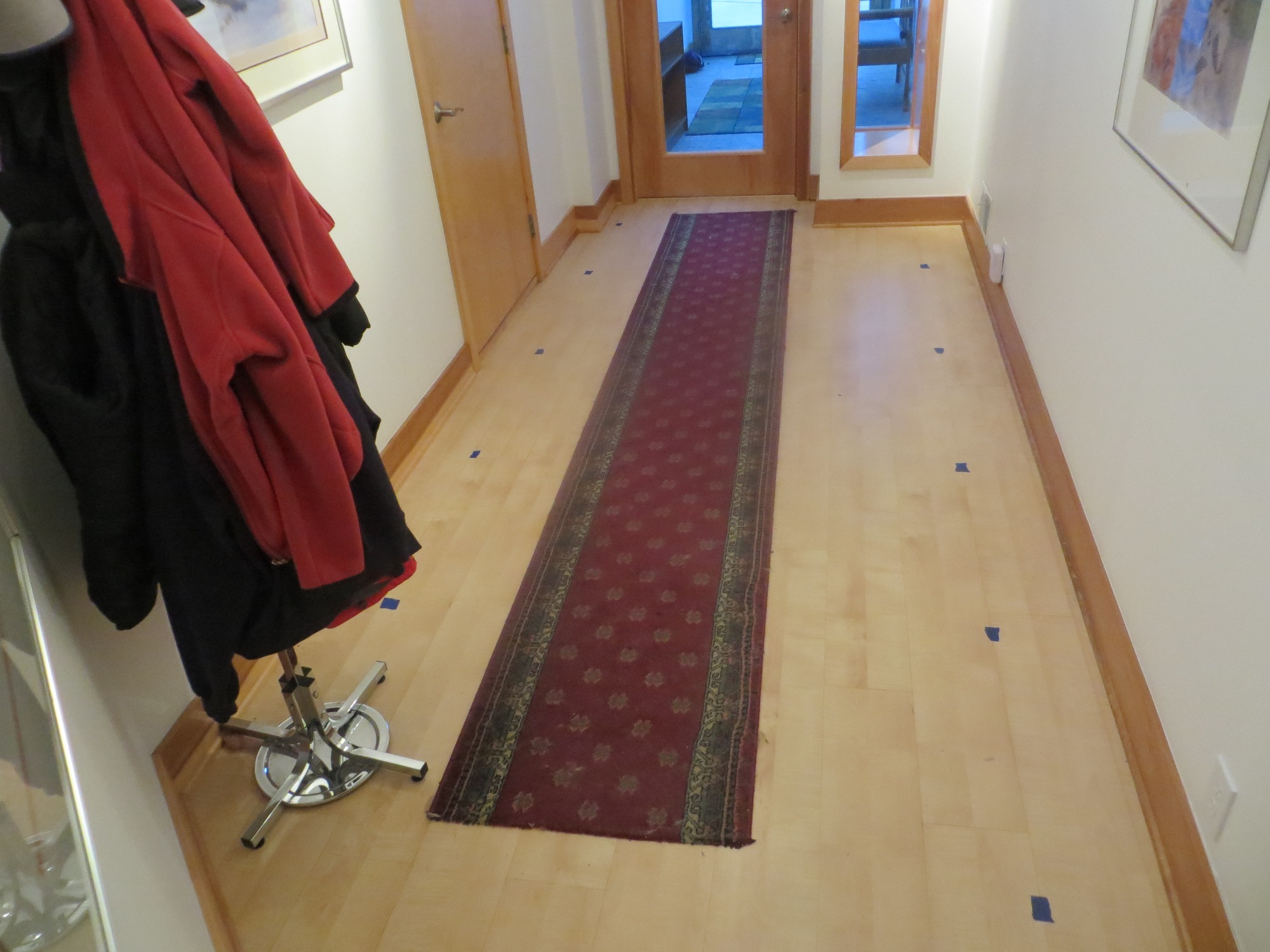
Experimental layout. Blue spots correspond to numbered/lettered position in layout diagram

Experimental layout. Blue spots correspond to numbered/lettered position in layout diagram

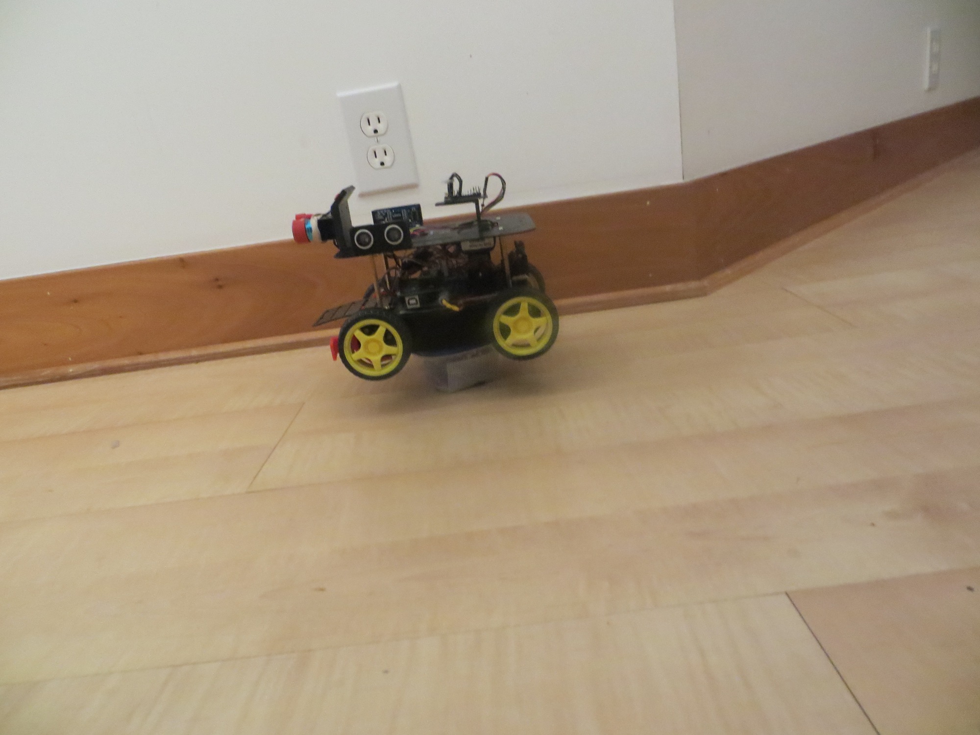
Wall-E2 on a pedestal so motors can run normally without moving the robot

Wall-E2 on a pedestal (at position ‘A’ in diagram) so motors can run normally without moving the robot

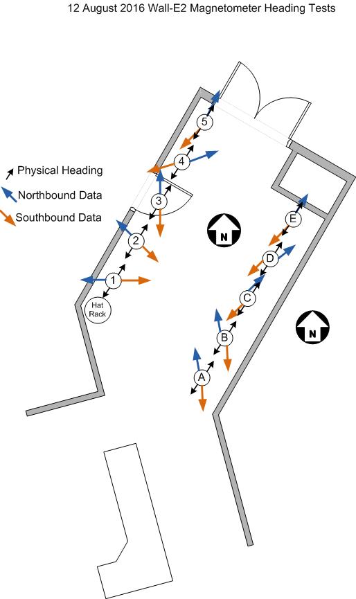
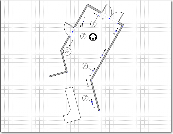
10-12 August Mag Heading Field Test Layout

10-12 August Mag Heading Field Test Layout

Data was collected at the positions shown by the  numbers from 1 to 5 along the west (garage) wall, and by the letters from A to F along the east wall.  At each position the robot was  placed on a pedestal and allowed to run for several seconds.  If the heading errors are caused by the physical characteristics of the hallway, then the collected data should be constant for each spot, and the data should correspond well to the heading data from my earlier continuous runs.

The above graphic shows the results of all 10 test positions.  For each position, data was collected with the robot oriented ‘north’ (actually about 020 deg) and ‘south’ (actually about 200 deg),  as denoted by the small black orientation arrows.  The ‘north’ heading  results are represented by the blue arrows, and the ‘south’ heading results are represented by the orange arrows.  There is no meaning associated with the length of the arrows.

Results:

  • Northbound and southbound data are almost exactly opposite each other at all points. To me, this indicates that the 3-axis magnetometer data and the heading values derived from that raw data are valid.
  • The data clearly shows that there is a significant  magnetic interferer in the vicinity of the west (garage) wall of the entry hallway.  The west wall data is skewed more significantly than the east wall results, indicating that the magnitude of the interference decreases from west to east. Since mag field intensity decreases as the cube of the distance, I infer that the interferer is very close to the west wall (if it were farther away, then the difference between the east and west wall results would be smaller, because the distance difference would be smaller).
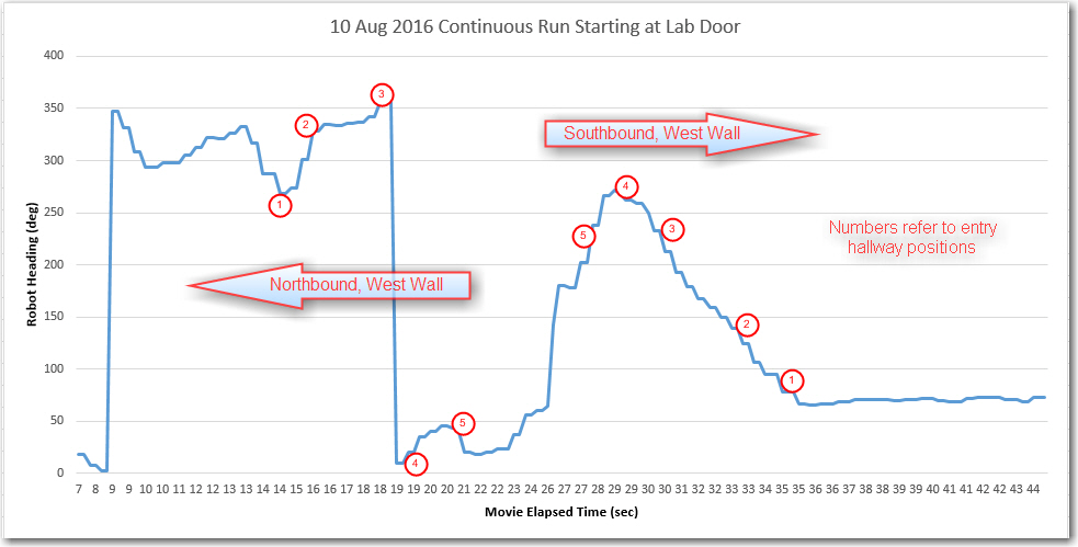
  • The data at each position corresponds well with data from the same position and orientation from the various continuous runs.  Given a continuous run and the knowledge of the interference pattern, it is possible to determine the robot’s location to a fair degree.  The following image shows the heading results from a 10 August continuous run, labelled with the position numbers from the entry hall layout diagram.  The positions were deduced from a movie of the run.
10 Aug continuous run, labelled with positions from the entry hall layout diagram

10 Aug continuous run, labelled with positions from the entry hall layout diagram

Conclusions:

  • The magnetometer and the heading calculation algorithm are probably working correctly
  • Magnetic interference is certainly a problem in the entry hallway next to the garage, and  may (or may not) be a problem elsewhere
  • Magnetic heading information may not be reliable/accurate enough to determine location with any precision, even coupled with left/right/front distances.

My next task is to run some continuous and step-by-step tests in other areas of the house, to determine if the entry hallway issue  is unique to the house or an ubiquitous problem.

Stay tuned!

Frank


Giving Wall-E2 A Sense of Direction, Part VIII

Posted 07/19/16

In my last post on this subject, I described moving my CK Devices ‘Mongoose’ IMU from a wooden stalk mounted on the 2nd deck to a more compact bracket mounted in the same location, and showed some data that indicated reasonable heading performance.  This post describes some ‘field’ (a hallway in my home) test results using the bracket-mounted configuration.

Field Test Site:

My ‘field test’ site consists of two hallway sections in my home. The two sections are oriented about 45 degrees to each other, as shown in the following diagram.

Field test area physical layout, oriented north-up

Field test area physical layout, oriented north-up

For my first ‘Field Test’, I simply set Wall-E2 loose at position 1, pointed in the direction shown in the diagram, and recorded via the  wixel-pair wireless connection implemented last December.  Wall-E2 successfully navigated (with a few ‘back-and-forth’ iterations) from point 1 to point 8 in the diagram, as shown in the following short video.

The captured telemetry data included the run time in seconds and the magnetic heading in degrees, and I sucked this information into Excel, where I graphed the mag heading versus time, as shown in the following screenshot.

Heading vs Time for Wall-E2 continuous run. Areas of puzzlement marked by '????'

Heading vs Time for Wall-E2 continuous run. Areas of puzzlement marked by ‘????’

As the caption notes, most of the graph makes sense, but there are at least two different areas where there is a more-or-less linear change of heading versus time, where there shouldn’t be any (or at least, where I don’t *think* there should be any).  Either Wall-E2 has some tricks up his sleeve that he wasn’t telling me about, or I don’t fully understand how the data and the physical record (the video) correspond.

Giving Wall-E2 a Sense of Direction, Part VII

Posted 07/11/16

My last post on this subject described my successful effort to mount my Mongoose IMU on Wall-E2, my wall-following robot.  I showed that the IMU, mounted on an 11cm wood stalk on Wall-E2’s top deck, when calibrated using my Magnetometer Calibration tool, provided reasonably accurate and consistent magnetic heading measurements.

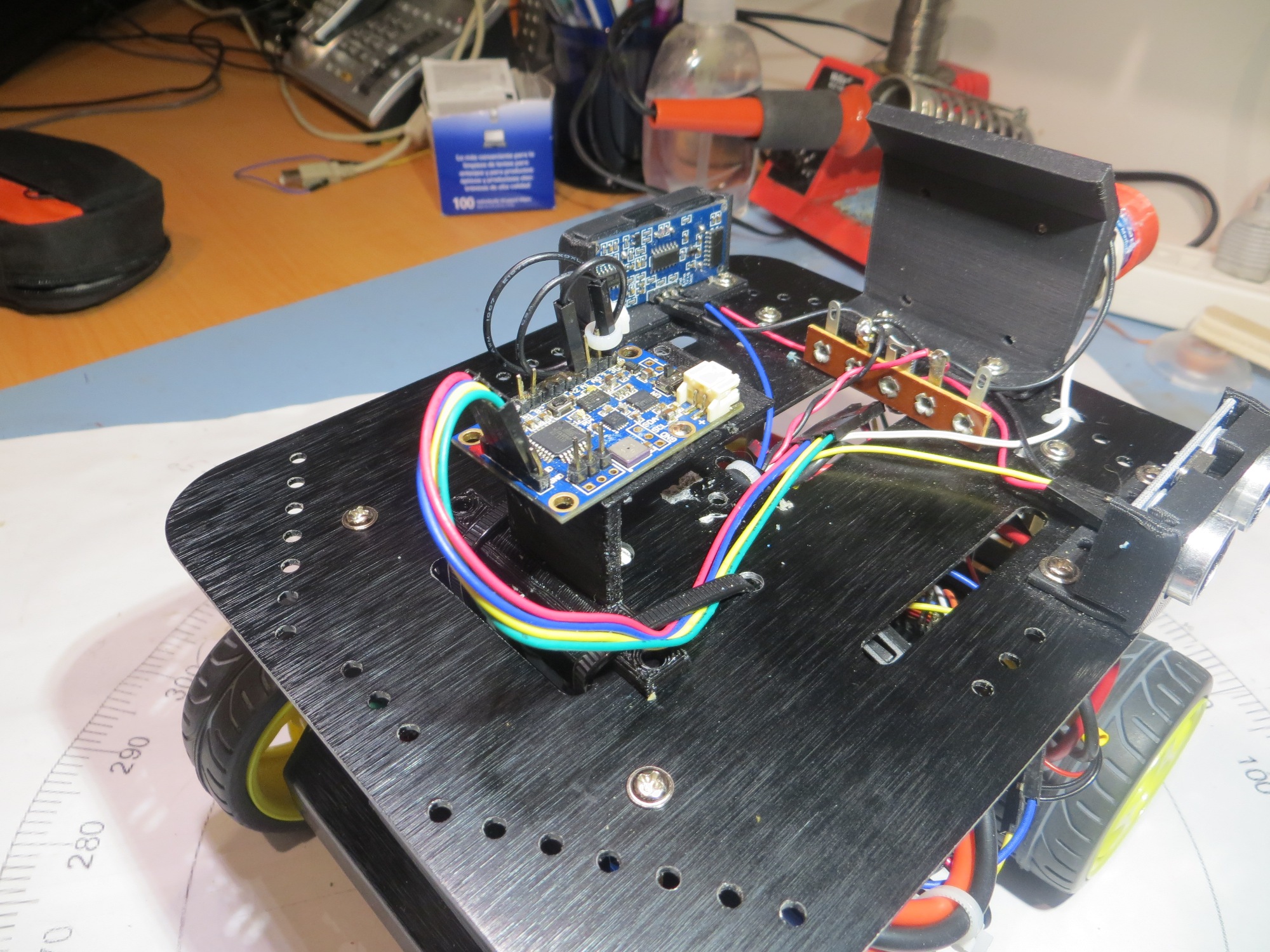
This post attempts to extend these results by replacing the long wooden stalk with a more compact plastic mounting bracket (actually my original IMU mounting bracket) as shown below

Mongoose IMU mounted on 2nd deck using original mounting bracket

Mongoose IMU mounted on 2nd deck using original mounting bracket

In an effort to determine what, if any, effect the stalk mounting had on IMU calibration, I decided to acquire and plot  calibrated (as opposed to raw) magnetometer data using my mag cal tool, and compare it to the results of the calibration performed on the stalk-mounted configuration.  Since I don’t currently save the ‘calibrated’ point-cloud (there’s no need, as all it does is show how well (or poorly) the raw mag data point cloud is transformed using the generated calibration matrix/center offset values), I first had to import the saved raw data from the stalk-mounted configuration and then regenerate the calibration values (and the resultant ‘calibrated’ point cloud).  Once this was done, then I can capture the new calibrated (i.e. calibrated using the previous stalk-mounted calibration values) but now in the lower mounting position.  If the stalk mounting had no additional isolation effect, the two point clouds should look identical.  If the stalk mounting  did have some effect, then the two clouds should look different.

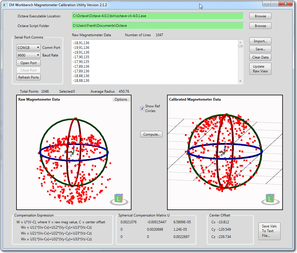
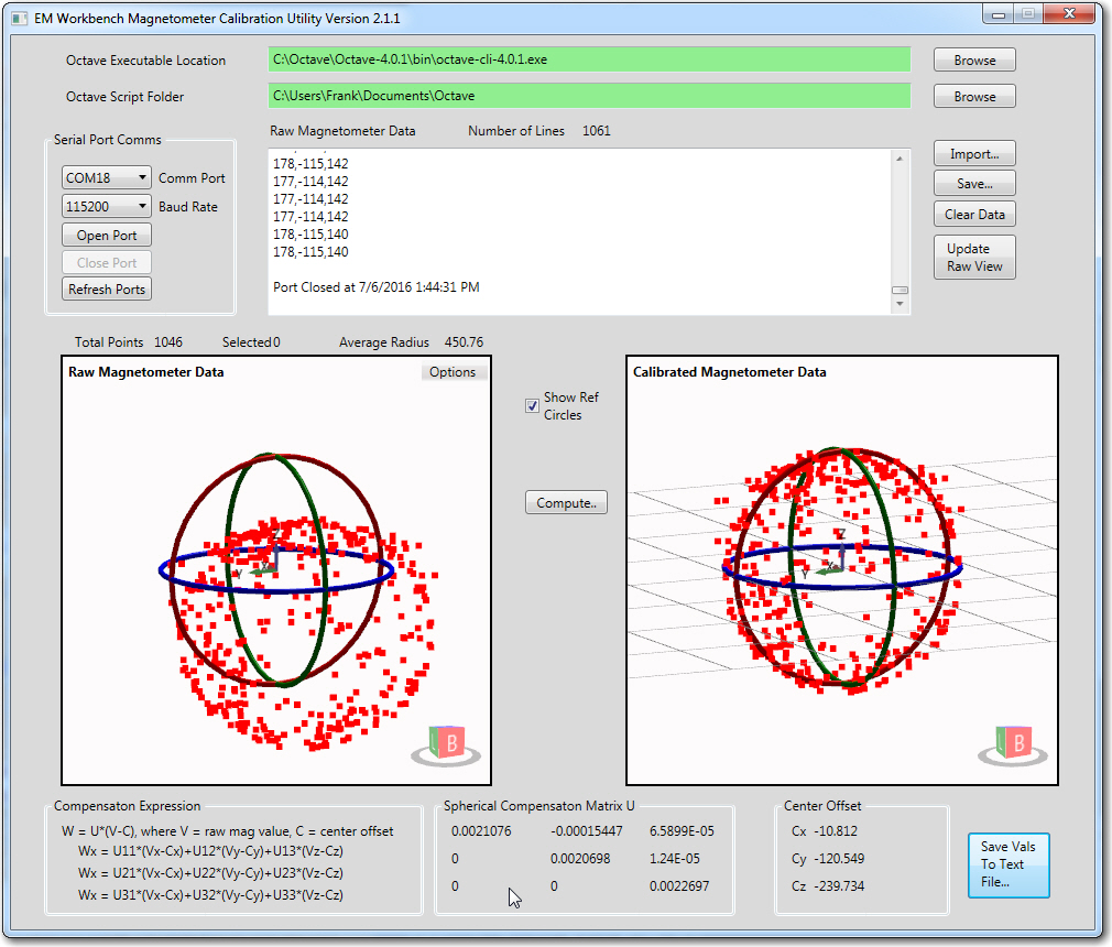
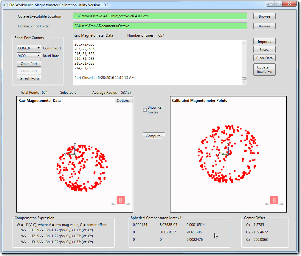
I started by launching the mag cal tool and importing  the raw mag data captured 07/06/16. Then I computed the calibration factors and the resulting ‘calibrated’ point cloud, as shown in the following screenshot.

Raw mag data from the stalk-mounted config, and the resulting calibrated point cloud

Raw mag data from the stalk-mounted config, and the resulting calibrated point cloud

As can be seen from the image, the data calibrated quite well, starting with a visibly offset point cloud with an average radius of about 450, and ending with a well-centered and symmetric point cloud with a radius close to 1.

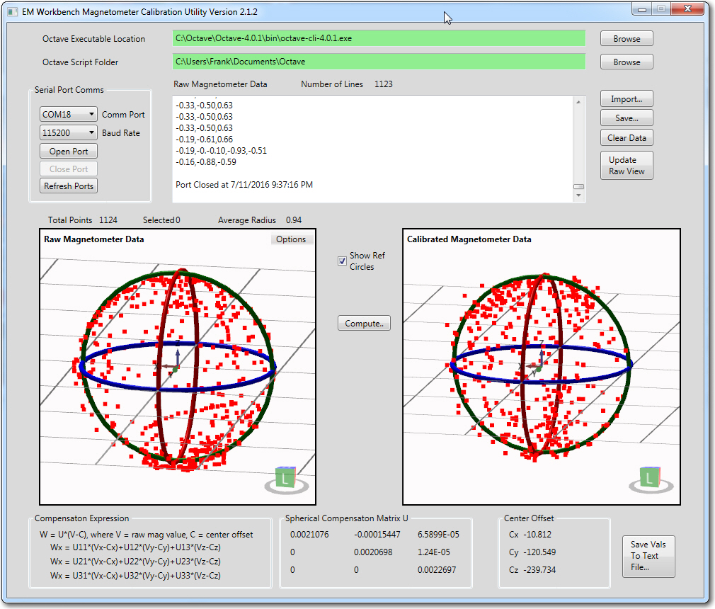
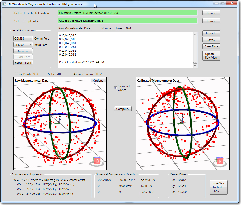
Next, I captured a set of data from the bracket-mounted IMU, using the calibration values from the 6 July stalk-mounted config (this required a bit of reprogramming to pare back the reporting from Wall-E2 to just the magnetometer 3-axis data).  The data was captured by manually rotating Wall-E2 about all 3 axes in a way that produced a well-populated ‘point cloud’ in the mag cal tool app.  During this run, Wall-E2 had power applied, and all motor drives enabled.

Bracket-mounted IMU calibrated magnetometer data vs 06 July stalk-mounted computed calibration data

Bracket-mounted IMU calibrated magnetometer data vs 06 July stalk-mounted computed calibration data, with Wall-E2 power on and motors running.

From the above screenshot it is quite clear that the stalk and bracket mounting configurations are essentially identical in terms of their calibrated performance.  This means I could, if I so chose, simply use the stalk-mounted calibration values and party on.  Moreover, if I do chose to re-calibrate, I wouldn’t expect to see much change in the calibration values.

Here’s a short movie showing the calibration process:


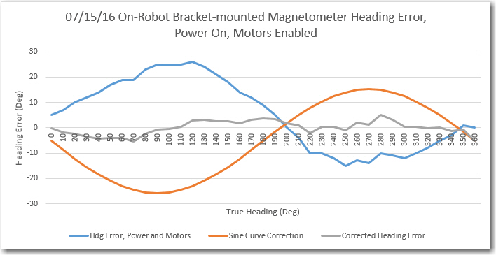
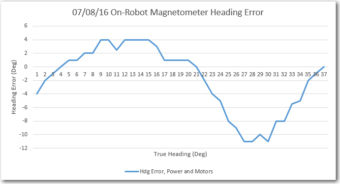
After noting  that the ‘stalk’ calibration values appeared to be reasonably valid for the bracket-mounted configuration, I re-ran the heading error tests on my bench-top heading range, with the following results:

Bracket-mounted IMU Heading Error, Power On, Motors Running

Bracket-mounted IMU Heading Error, Power On, Motors Running

For comparison, here is the ‘stalk’ heading error chart

Stalk-mounted Mongoose IMU, with power and motor drive enabled.

Stalk-mounted Mongoose IMU, with power and motor drive enabled.

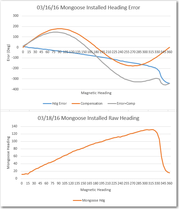
And the original problem measurement from back in March with the IMU mounted on the first deck at the front of the robot:

Heading performance for front-mounted IMU, power off.

Heading performance for front-mounted IMU, power off.

From the above, it is kind of hard for me to believe that this much error could possibly be corrected just via the calibration matrix and center offset adjustments, so I suspect the current performance depends as much on moving the IMU from directly over the front motors to the 2nd deck (a minimum of 10cm from the rear motors, and about 15 from the front ones) as it does on the calibration values.  I could verify this by re-mounting the IMU on the front and seeing if I could calibrate out the errors, but I’d rather let sleeping dogs lie at this point ;-).

Frank


Giving Wall-E2 A Sense of Direction, Part VI

Posted July 06, 2016

In my last post  on this subject, I had used my newly-completed Magnetometer Calibration Tool to generate calibration factors for my HMC5883L-based ‘Mongoose IMU board, and compare the ‘raw’ vs ‘calibrated’ performance in a ‘free-space’ (actually my wood lab workbench) environment.  The result of the comparison showed  that the  ‘calibrated’ performance was pretty much unchanged from the ‘raw’ setup, indicating that the test setup (on my wooden workbench) wasn’t significantly affected by ‘hard’ or ‘soft’ interference.

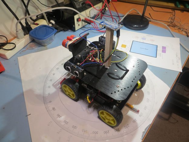
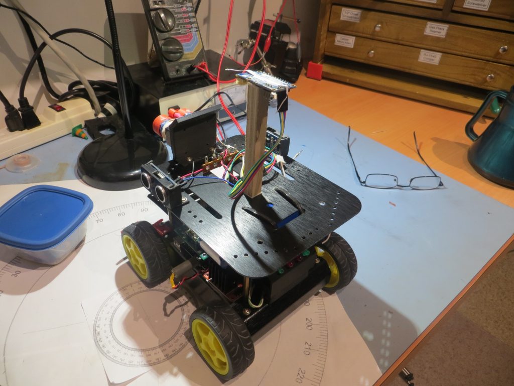
The next step is to mount the Mongoose IMU on Wall-E2, my 4WD wall-tracking robot to see if the magnetometer can be compensated for DC motor magnet fields, power cables, and the like.  I decided to start this process by mounting the IMU on a wooden ‘stalk’ on the second deck, to see if this placement would minimize the above interfering effects.

Mongoose IMU mounted on wooden stalk on 2nd deck

Mongoose IMU mounted on wooden stalk on 2nd deck

Raw and calibrated data. Reference circles on left have radii equal to average raw value radius. Circles on right all have a radius == 1

Raw and calibrated data. Reference circles on left have radii equal to average raw value radius. Circles on right all have a radius == 1

The calibration values can now be saved to a text file convenient for transcription into the user’s calibration routine.  After doing the save, the text file looks like the following;

After copy/pasting the above values into my calibration routine and re-running the data collection exercise but recording the calibrated magnetometer readings instead, I got the following ‘raw’ (calibrated magnetometer data, but displayed in the ‘raw’ view) results.

The displayed data in the 'raw' view is new magnetometer data after being calibrated with the results of the first run. The circle radius on the left is 0.92. The data on the left is the old magnetometer data, calibtrated using the results of the calibration value computation from the first set of raw magnetometer data

Comparison of new calibrated data from the magnetometer with the results of the Octave calibration algorithm as applied to the old set of raw magnetometer data.

The displayed data in the ‘raw’ view is new magnetometer data after being calibrated with the results of the first run. The circle radius on the left is 0.92. The data on the left is the old magnetometer data, calibtrated using the results of the calibration value computation from the first set of raw magnetometer data.  As is easily seen from the two views, the calibration values generated by the Octave program produce very good ‘on-the-fly’ calibration results.

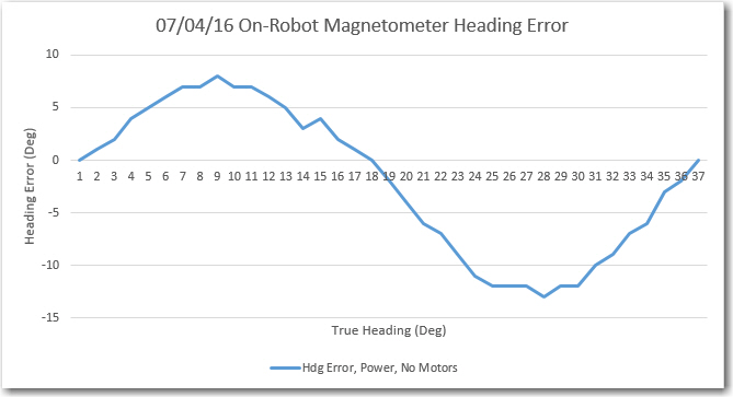
After calibration, I re-ran the heading performance tests (main power ON, but no drive to the motors), with the following results

Stalk-mounted magnetometer heading error, main power, no motor drive

Stalk-mounted magnetometer heading error, main power, no motor drive

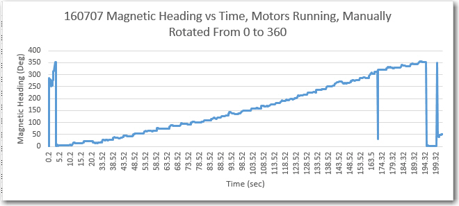
The next step is to repeat this experiment with the motor drives enabled.  Here’s the results of a quick run.  With the motors enabled, I held Wall-E2 so that it’s wheels didn’t quite touch the surface, and slowly rotated the robot 360 clockwise, starting at the same point (nominally 0 deg as reported by the Mongoose IMU) as in the above plot.

Manually rotated over 360 degrees with motors running. Mongoose stalk mounted on 2nd deck

Manually rotated over 360 degrees with motors running. Mongoose stalk mounted on 2nd deck

As shown in the plot above, the headings reported by the Mongoose IMU increased monotonically as the robot was rotated clockwise from nominal zero. Although just a preliminary result, it  is actually quite encouraging, as it indicates that running the motors doesn’t significantly affect the heading value reported by the Mongoose IMU.

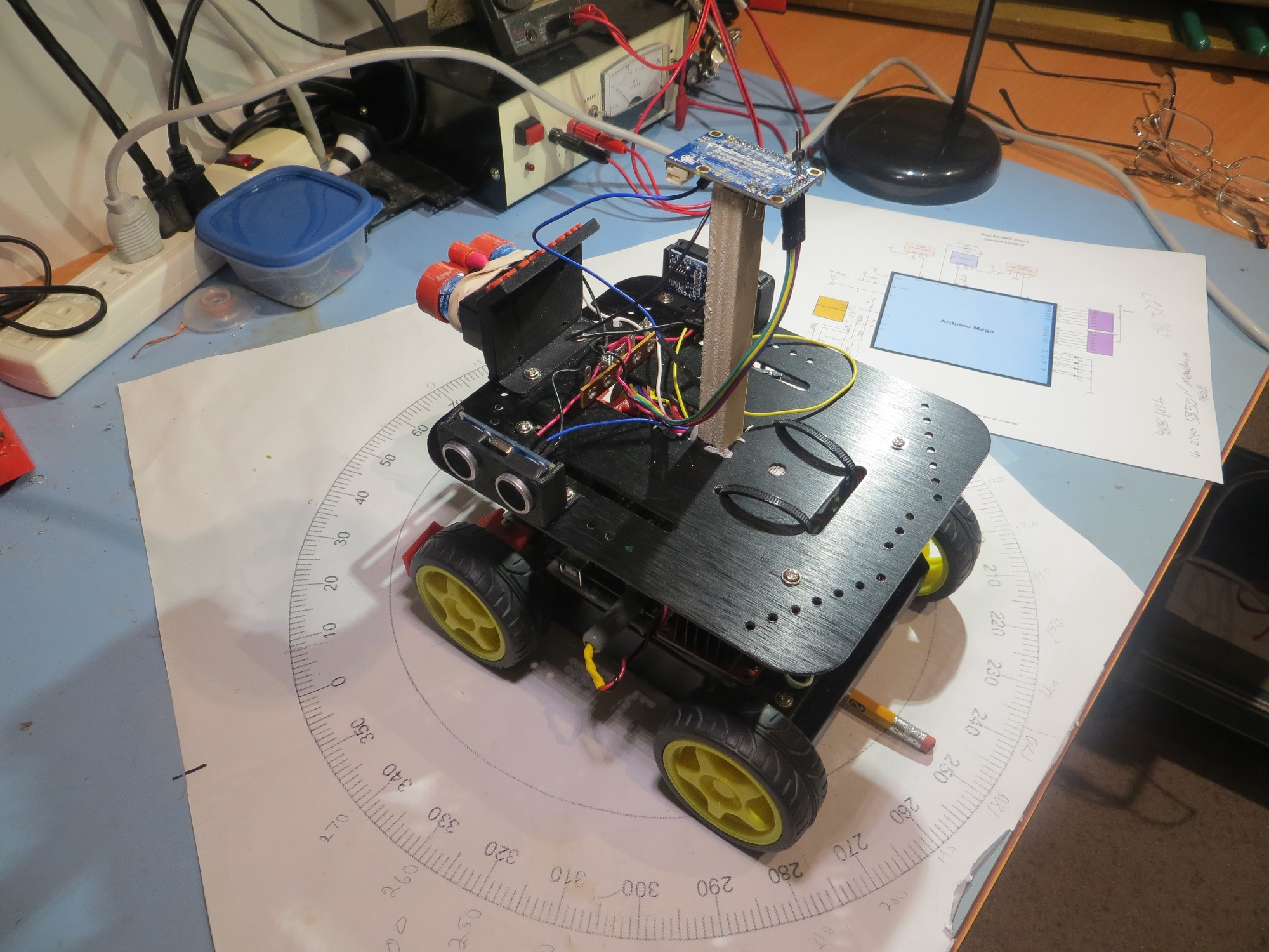
Today I had the chance to perform a ‘motors running’ heading error experiment with the stalk-mounted Mongoose IMU.  The robot body was placed on a small plastic box such that the wheels were free to turn without touching the workbench.  Then it was manually rotated in 10 deg increments as before.  The experimental setup and the results are shown below.

Test setup for the "Power and Motors" IMU heading error experiment.

Test setup for the “Power and Motors” IMU heading error experiment.

Stalk-mounted Mongoose IMU, with power and motor drive enabled.

Stalk-mounted Mongoose IMU, with power and motor drive enabled.

Comparing the heading error plots, it is pretty clear that enabling the motors does not significantly affect the stalk-mounted IMU.  If I wanted to leave the IMU mounted on the stalk, it appears that I could expect to get reasonable, if not spectacularly accurate, magnetic heading readings ‘in real life’.

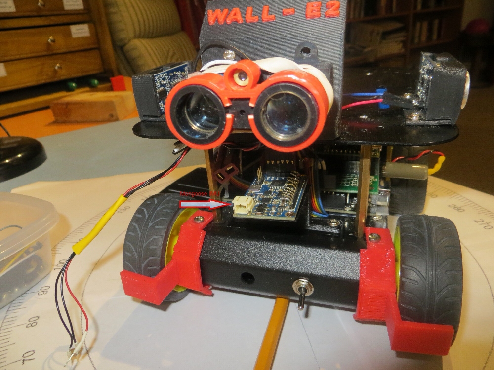
However, I really  don’t want to leave the IMU mounted on a stalk, so the next step in the process will be to replace the stalk mounting arrangement with a more ‘streamlined’ mounting setup.  For this I plan to use the mounting bracket I printed up for the original front-mounted setup (see image below), but attached to the 2nd deck vs the 1st.

160318MongooseInstalled1_Annotated2

Original mounting location for the Moongoose IMU (arrow points to the IMU)


Magnetometer Calibration Tool, Part IV

In my  last episode of the Magnetometer Calibration Tool soap opera, I had a ‘working’ WPF application that could be used to generate a 3×3 calibration matrix and 3D center offset value for any magnetometer capable of producing  3D magnetometer values  via a serial port.  Although the tool worked, it had a couple of ‘minor’ deficiencies:

  • My original Eyeshot-based tool sported a very nice set of 3D reference circles in both the ‘raw’ and ‘calibrated viewports.  In the ‘raw’ view, the circle radii were equal to the average 3D distance of all  point cloud points from the center, and in the ‘calibrated’ view the circle radii were exactly 1.  This allowed the user to readily visualize any deviations from ideal in the ‘raw’ view, and the (hopefully positive) effect of the calibration algorithm.  This feature was missing from the WPF-based tool, mainly because I couldn’t figure out how to do it :-(.
  • The XAML and ‘code-behind’ associated with the project was a god-awful mess!  I had tried lots and lots of different things while blindly stumbling toward a ‘mostly working’ solution, and there was a  LOT of dead code and inappropriate structure still hanging around.  In addition to being ugly, this state of affairs also reflected my (lack of) understanding of basic WPF/Helix Toolkit concepts, principles, and methods.

So, this post describes my attempts to rectify both of these problems.  Happily, I can report that the first one (lack of switchable reference circles) has been completely solved, and the second one (god-awful mess and lack of understanding) has been at least partially rectified; I have a much better (although not complete by any means!) grasp of how XAML and ‘code-behind’ works together to produce the required visual effects.

To achieve better understanding of the connection between the 3D viewport implemented in Helix Toolkit by the HelixViewport3D object, the XAML that describes the window’s layout, and the ‘code-behind’ C# code, I spent a lot of quality time working with and modifying the Helix Toolkit’s ‘Simple Demo’ app.  The ‘Simple Demo’ program displays 3 box-like objects (with some spheres I added) on a grid, as shown below
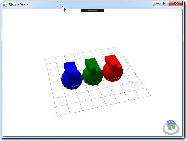
Simple Demo WPF/Helix Toolkit Application

Simple Demo WPF/Helix Toolkit Application (spheres added by me)
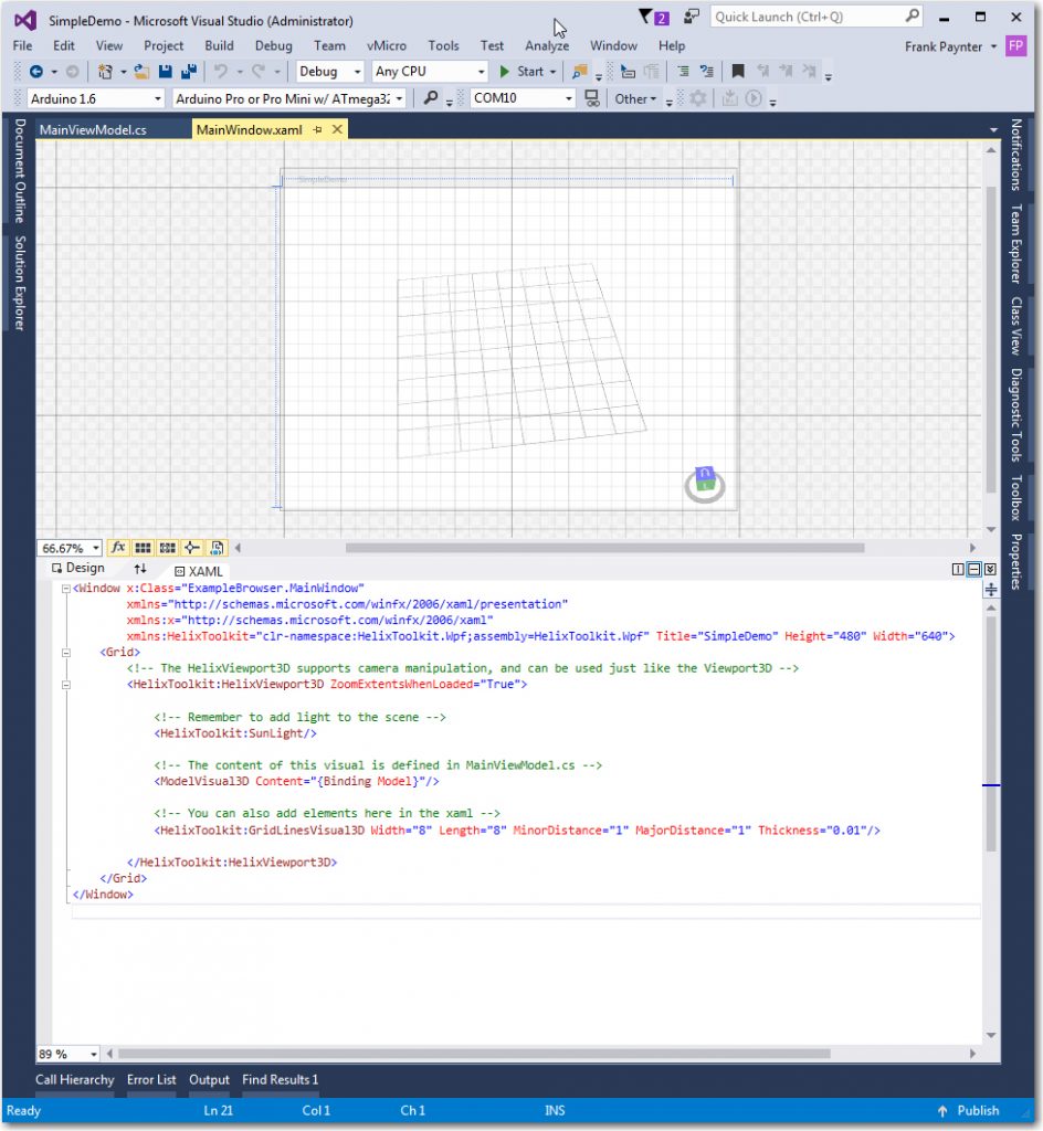
Simple Demo XAML View

Simple Demo XAML View – no changes from original
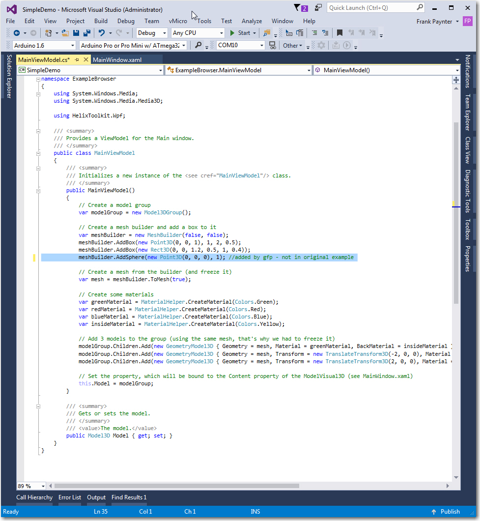
Simple Demo 'Code-behind', with my addition highlighted

Simple Demo ‘Code-behind’, with my addition highlighted

My aim in going back to the ‘Simple Demo’ was to avoid  the distraction of my more complex window layout (2 separate HelixViewport3D windows and  lots of other controls) and the associated C#/.NET code so I could concentrate on one simple task – how to  implement a set of 3D reference circles that can be switched on/off via a windows control (a checkbox in my case).  After trying a lot of different things, and with some clues garnered from the Helix Toolkit forum, I settled on the TubeVisual3D object to construct the circles, as shown in the following screenshots.  I used an empirically determined ‘thickness factor’ of 0.05*Radius for the ‘Diameter’ property to get the ‘thick circular line’ effect I wanted.
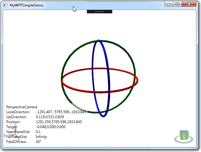
Simple Demo modified to implement TubeVisual3D objects

Simple Demo modified to implement TubeVisual3D objects.  The original box/sphere stuff is still there, just too small to see
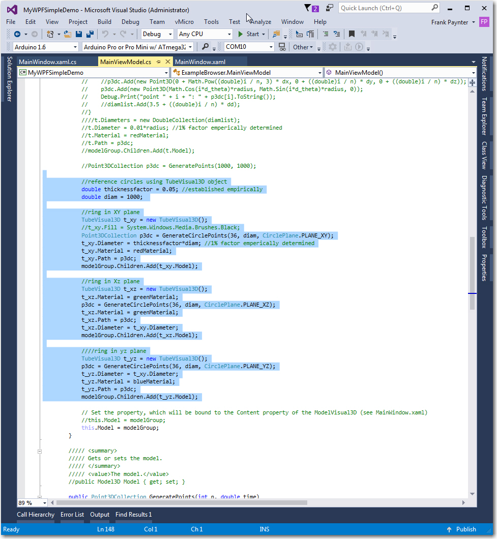
MyWPFSimpleDemo 'code-behind', with TubeVisual3D implementation code highlighted

MyWPFSimpleDemo ‘code-behind’, with TubeVisual3D implementation code highlighted.  Note all the ‘dead’ code where I tried to use the EllipsoidVisual3D model for this task.

Next, I had to figure out a way of switching the reference circle display on and off using a windows control of some sort, and this turned out to be frustratingly difficult.  It was easy to get the circles to show up on program startup – i.e. with model construction and the connection to the viewport established in the constructor(s), but I could not figure out a way of doing the same thing after the program was already running.  I knew this had to be easy – but damned if I could figure it out!  Moreover, after hours of searching the blogosphere, I couldn’t find anything more than a few hints about how to do it. What I  did find was a lot of WPF beginners like me with the same problem but no solutions – RATS!!

Finally I twigged to the fundamental concept of WPF 3D visualization – the connection between a WPF viewport (the 2D representation of the desired  3D model) and the ‘code-behind’ code that actually represents the 3D entities to be displayed must be defined at program startup, via the following constructs:

  • In the XAML, a line like  ‘<ModelVisual3D Content=”{Binding Model}”/>, where Model is the name of a  Model3D property declared in the  ‘code-behind’ file (MainViewModel.cs in my case)
  • In MainWindow.xaml.cs, a  line like ‘this.DataContext = mainviewmodel’, where mainviewmodel is declared with ‘public MainViewModel mainviewmodel = new MainViewModel();’
  • In MainViewModel.cs, a line like ‘ public Model3D Model { get; set; }’, and in the class constructor, ‘Model = new Model3DGroup();’
  •  in MainViewModel.cs, the line ‘var modelGroup = new Model3DGroup();’ at the top of the model creation section to create a temporary Model3DGroup object, and the line ‘ this.Model = modelGroup;’ at the bottom of the model construction code. This line sets the Model property contents to the contents of the temporary modelGroup‘ object

So, the ‘MainViewModel’ class is connected to the Windows window  class in MainWindow.xaml.cs, and the 3D model described in the MainViewModel class is connected to the 3D viewport via the Model Model3DGroup object.  This is all done at initial object construction, in the various class constructors.  There are still some parts of this that I do not understand, but I think I have it mostly correct.

The important concept that I was missing  is the above connections have been made at program startup and cannot (AFAICT) be changed once the program starts, but the contents of the temporary  Model3DGroup object (i.e. the ‘Children’ objects in the model group) can be changed, and the new contents will be reflected in the viewport when it is next updated.  Once I understood this concept, the rest, as they say, “was history”.  I implemented a simple control handler that cleared the contents of the temporary Model3DGroup object modelGroup and regenerated it (or not, depending on the state of the ‘Show Ref Circles’ checkbox).  Simple and straightforward, once I knew the secret!

So this ‘aha’ moment allowed me to implement the switchable reference circles in my Magnetometer calibration tool and check off the first of the deficiencies noted at the start of this post.  The new reference circle magic is shown in the following screenshots.
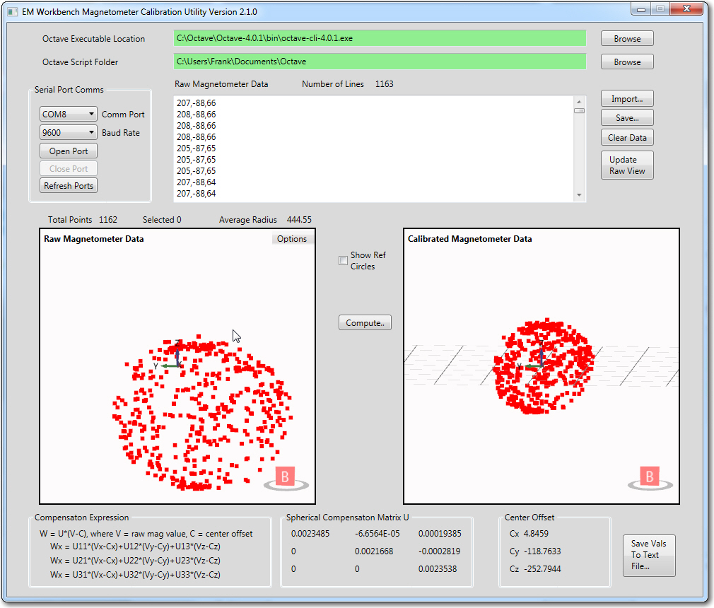
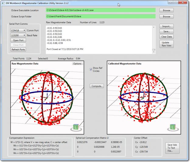
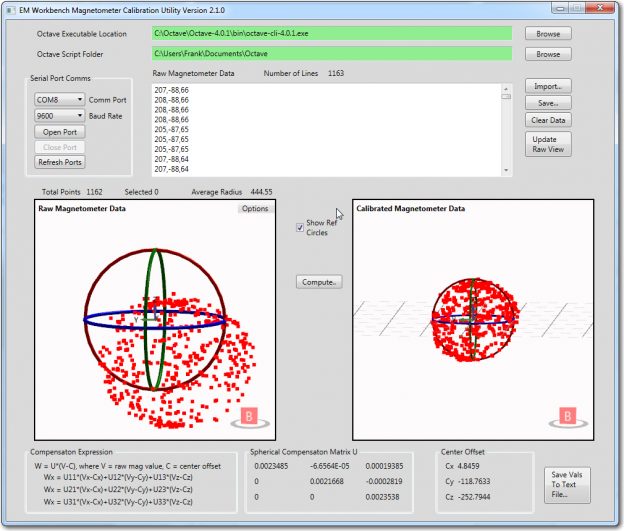
Raw and calibrated magnetometer data. Calculated average radius of the raw data is about 444 units, and the assumed average radius of the calibrated data is close to 1 unit
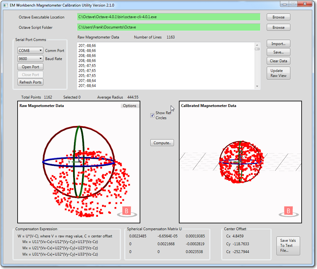
Raw and calibrated magnetometer data. Calculated average radius of the raw data is about 444 units, and the assumed average radius of the calibrated data is close to 1 unit

Raw and calibrated magnetometer data, with reference circles shown. The radius of the 'raw' circles is equal to the calculated average radius of about 444 units, and the assumed average radius of the calibrated circles is exactly 1 unit

Raw and calibrated magnetometer data, with reference circles shown. The radius of the ‘raw’ circles is equal to the calculated average radius of about 444 units, and the assumed average radius of the calibrated circles is exactly 1 unit

The reference circles make it easy to see how the calibration process affects the data.  In the ‘raw’ view, it is apparent that the data is significantly offset from center, but still reasonably spherical.  In the calibrated view, it is easy to see that the calibration process centers the data, removes most of the non-sphericity, and scales everything to very nearly 1 unit – nice!

Now for addressing the second of the two major deficiencies noted at the start of this post, namely “The XAML and ‘code-behind’ associated with the project was a god-awful mess! “.

With my current understanding of a typical WPF-based application, I believe the application architecture consist of three parts – the XAML code (in MainWindow.xaml)    that describes the window layout,  the ‘MainWindow’ class (in MainWindow.cs) that contains the interaction logic with the main window, and a class or classes that generate the 3D models to be rendered in the main window.  For  my magnetometer calibration tool  I created  two 3D model generation classes – ViewportGeometryModel and RawViewModel.  The ViewportGeometry class is the base class for RawViewModel, and handles generation of the three orthogonal TubeVisual3D ‘circles.  The  ViewportGeometryModel class is instantiated directly (as ‘calmodel’ in the code) and connected to the main window’s ‘vp_cal’ HelixViewport3D window via it’s ‘GeometryModel’ Model3D property, and the derived class RawViewModel (instantiated in the code as ‘rawmodel’) is similarly connected to the main window’s ‘vp_raw’ HelixViewport3D window via the same  ‘GeometryModel’ Model3D property (different object instantiation, same property name).

The ViewportGeometryModel class has one main function, and some helper stuff.  The main function  is  ‘DrawRefCircles(HelixViewport3D viewport, double radius = 1, bool bEnable = false)’.  This function is called from MainWindow.xaml.cs as follows:

The ‘DrawRefCircles()’ function creates a new ModelGroup3D object if necessary, and optionally fills it with three TubeVisual3D objects of the desired radius and thickness, as shown below

The last line in the above function is ‘GeometryModel = modelGroup;’, where ‘GeometryModel’ is declared in the ViewGeometryModel class as

and bound to the appropriate HelixViewport3D window via

Line in MainWindow.xaml that binds the HelixViewport3D to the 'GeometryModel' Model 3D property of the ViewportGeometryModel class

Line in MainWindow.xaml that binds the HelixViewport3D to the ‘GeometryModel’ Model 3D property of the ViewportGeometryModel class (and/or its derived class RawViewModel). The line shown here is for the raw viewport, and there is an identical one in the calibrated viewport section.

Now, instead of a mishmash spaghetti factory, the program is a lot more organized, modular, and cohesive (or at least I think so!).  As the following screenshot shows, there are only a few classes, and each class does a single thing.  Mission accomplished!
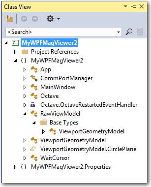
Magnetometer calibration tool class diagram. Note that the RawViewModel is a derived class from VieportGeometryModel

Magnetometer calibration tool class diagram. Note that the RawViewModel is a derived class from VieportGeometryModel.  The ViewportGeometryModel.CirclePlane ‘class is an Enum

Other Stuff:

This entire post has been a description of how I figured out the connections between a WPF-based windowed application with two HelixViewport3D 3D viewports (and lots of other controls) and the XAML/code-behind elements that generate the 3D models to be rendered. In particular it has been a description of the ‘reference circle’ feature for both the ‘raw’ and ‘calibrated’ views.  However, these circles are really only a small part of the overall magnetometer calibration tool; a much bigger part of the 3D view are  the point-clouds in both the raw and calibrated views that depict the actual 3D magnetometer values acquired from the magnetometer being calibrated, before and after calibration.  I didn’t say anything about these point-cloud collections, because I had them working long before I started the ‘how can I display these damned reference circles’ odyssey.  However, I thought it might be useful to point out (no pun intended) some interesting tidbits about the point-cloud implementation.

  • I implemented the point-cloud using the Helix Toolkit’s PointsVisual3D and Point3DCollection objects.  Note that the PointsVisual3D object is derived from ScreenSpaceVisual3D which is derived from RenderingModelVisual3D  instead of a geometry object like TubeVisual3D which is derived from  ExtrudedVisual3D, which in turn is derived from  MeshElement3D.   These are very different inheritance chains.  A  PointsVisual3D object can be added directly to a HelixViewport3D object’s Children collection,  and doesn’t need a light for rendering!  I can’t tell you how much agony this caused me, as I just couldn’t understand why other objects added via the ModelGroup chain either didn’t render at all, or rendered as flat black objects.  Fortunately for me, the ‘SimpleDemo’ app  did have light already defined, so things displayed normally (it still took me a while to figure out that I had to add a light to my MagCal app, even though the point-cloud displayed fine).
  • Points in a point-cloud collection don’t support a ‘selected’ property, so I had to roll my own selection facility.  I did this by handling the mouse-down event, and manually checking the distance of each point in the collection from the mouse-down point.  If I found a point(s) close enough, I manually moved the point from the ‘normal’ point-cloud to a ‘selected’ point-cloud, which I rendered slightly larger and with a different color.  If a  point became ‘unselected’, I manually moved it back into the ‘normal’ point-cloud object.  A bit clunky, but it worked.

All of the source code, and a ZIP file containing everything (except Octave) needed to run the Magnetometer Calibration app is available at my GitHub site –  https://github.com/paynterf/MagCalTool

Frank


Giving Wall-E2 A Sense of Direction, Part VI

Posted 06/28/16

In my last post on this subject, I  used  my new Magnetometer to generate calibration matrix/center offset values for my Mongoose IMU (which uses a HMC5883 3-axis magnetometer), in a ‘free space’ (no nearby magnetic interferers) environment, and showed that I could incorporate these values into the Mongoose’s firmware.  In this post, I describe my efforts to  calibrate the same Mongoose IMU, but now mounted on Wall-E2, my 4WD wall-following robot.

160318MongooseInstalled1_Annotated2

Mongoose IMU (see arrow) mounted on front of Wall-E2

A long  time ago, in a galaxy far, far away (actually 3 months  ago,  in the exact same galaxy), I had the Mongoose IMU mounted on the front of my robot, as shown in the above  image.  Unfortunately, when I tried to use the heading data from the Mongoose (see Giving  Wall-E2 a Sense of Direction, Part IV), it was readily apparent that something was badly wrong.  Eventually I figured out that the problem was the magnetic fields associated with the drive motors that were causing the problem, and I wouldn’t be able to do much about that without some sort of calibration exercise.  After this realization I tried, unsuccessfully, to find a magnetometer calibration tool that I liked.  Failing that, I wrote my own (twice!), winding up with the WPF-based application described in ‘Magnetometer Calibration, Part III‘.

So, now the idea is  to re-mount the Mongoose IMU on Wall-E2, and use my newly-created calibration tool to compensate for the magnetic interference generated by the DC motors and operating currents.  As a first step in that direction, I decided to mount the IMU on a wooden stalk on the top of the robot, thereby gaining as much separation from the motors and other interferers as possible.  If this works, then I will try to reduce the height of the stalk as much as possible.

The image below shows the initial mounting setup.

Mongoose IMU mounted on wood stalk

Mongoose IMU mounted on wood stalk

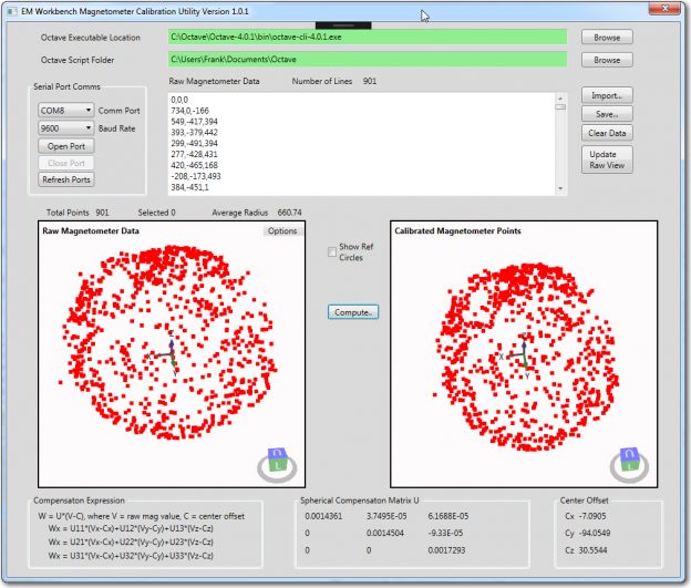
With the Mongoose mounted as shown, I used my magnetometer calibration tool to generate a calibration matrix and center offset, as shown in the following image.

Calibration run for Mongoose IMU mounted on wood stalk on top of Wall-E2

Calibration run for Mongoose IMU mounted on wood stalk on top of Wall-E2


Giving Wall-E2 A Sense of Direction, Part V

Posted 06/18/16

My last few posts have described my efforts to create an easy-to-use magnetometer calibration utility to allow for as-installed  magnetometer calibration.  In situ calibration is necessary for magnetometers because they can be significantly affected by nearby ‘hard’ and ‘soft’ iron interferers.  In my research on this topic, I discovered there were two main magnetometer calibration methods; in one, 3-axis magnetometer data is acquired with the entire assembly containing the magnetometer placed in a small but complete number of well-known positions.  The data is then manipulated to generate calibration values that are then used to convert magnetometer data at an arbitrary position.  The other method involves  acquiring a large amount (hundreds or thousands of points) of data while the assembly is rotated arbitrarily around all three axes.  The compensation method assumes the acquired data is sufficiently varied to cover the entire 3D sphere, and then finds the best fit of the data to a perfect sphere centered at the origin.  This produces an upper triangular 3×3 matrix of multiplicative values and an offset vector that can be used to convert any magnetometer position raw value to a compensated one.  I decided to create a tool using the second method, mainly because I had available a MATLAB script that would do most of the work for me, and Octave, the free open-source application that can execute most MATLAB scripts.  Moreover, Octave for windows can be called from C#/.NET programs, making it a natural fit for my needs.  In any case, I was able to implement the utility (twice!!) over the course of a couple of months, getting it to the point where I am now ready to try calibrating my CK Devices ‘Mongoose’ IMU, as installed on my ‘Wall-E2’ four-wheel drive robot.

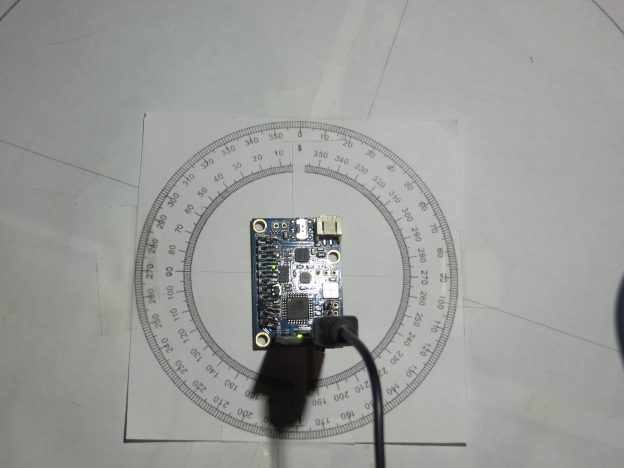
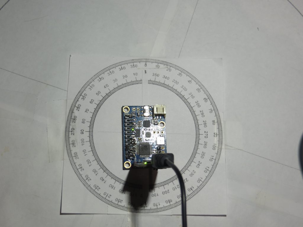
However, before mounting the IMU on the robot and going for ‘the big Kahuna’ result, I decided to essentially re-create my original experiment with the IMU rotated in the X-Y plane on my bench-top, as described in the post ‘Giving Wall-E2 A Sense of Direction – Part III‘.  My 4-inch compass rose had long since bitten the dust, but I had saved the print file (did I tell you that I  never throw anything away)

Mongoose IMU on 4-Inch Compass Rose

Mongoose IMU on 4-Inch Compass Rose

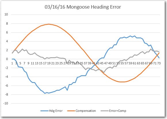
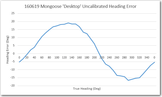
So, I basically re-created the original heading error test from back in March, and got similar (but not identical) results, as shown below:

Heading Error, Compensation, and Comp+Error

Heading Error, Compensation, and Comp+Error

06/19/16 Mongoose 'Desktop' Heading Error

06/19/16 Mongoose ‘Desktop’ Heading Error

Then I used my newly minted magnetometer calibration utility to generate a calibration matrix and center offset, so I can apply them  to the above data.  However, before I can do that I have to go back into CK Devices original code to find out where the calibration should be applied – more digging :-(.

In the original Mongoose IMU code, the function ‘ReadCompass()’ in HMC5883L.ino gets the raw values from the magnetometer  and  generates compensated values using whatever values the user places in two ‘struct’ objects (all zeros by default).  However, I was clever enough to only send the ‘raw’ uncalibrated magnetometer data to the serial port, so that is what I’ve been using as ‘raw’ data for my mag calibration tool – so far, so good.  However, what I need for my robot is compensated values, so (hopefully) I can (accurately?) determine Wall-E2’s heading.

So, it appears I have two options here; I can continue to emit ‘raw’ data from the Mongoose and perform any needed compensation externally, or I can do the compensation internally to the Mongoose and emit only corrected mag data.  The problem with the latter option (internal to the Mongoose) is that I would have to defeat it each time the robot configuration changed, with it’s inevitable change to the magnetometer’s surroundings.  If I write an external routine to do the compensation based on the results from the calibration tool, then it is only that one routine that will require an update.  OTOH, If the compensation is internal to the Mongoose, then modularity is maximized – a very good feature.  The deciding factor is that if the routine is internal to the Moongoose, then I can remove it from the robot and I still have a complete setup for magnetometer work.  So, I decided to write it into the Mongoose code,  but have the ability to switch it in/out with a compile time switch (something like NO_MAGCOMP?)

The compensation expression being implemented is:

W = U*(V-C), where U = spherical compensation matrix, V = raw mag values, C = center offset value

Since U is always upper triangular (don’t ask – I don’t know why), the above matrix expression simplifies to:

Wx = U11*(Vx-Cx) + U12*(Vy-Cy) + U13*(Vz-Cz)
Wy = U22*(Vy-Cy) + U23*(Vz-Cz)
Wz = U33*(Vz-Cz)

I implemented the above expression in the Mongoose firmware by adding a new function ‘CalibrateMagData()’ as follows:

Using the already existing s_sensor_data struct which is defined as follows:

Then I created another ‘print’ routine, ‘PrintMagCalData()’ to print out the calibrated (vs raw) magnetometer data. Also, after an overnight dream-state ‘aha’ moment, I realized I don’t have to incorporate a compile-time #ifdef statement to switch between ‘raw’ and ‘calibrated’ data readout from the Mongoose – I simply attach a jumper from either GND or +3.3V to one of the I/O pins, and implement code that calls either ‘PrintMagCalData()’ or ‘PrintMagRawData()’ depending on the HIGH/LOW state of the monitor pin. Now  that’s elegant! 😉

After making these changes, I fired up just the Mongoose using VS2015 in debug mode, which includes a port monitor function.  As soon as the Moongoose came up, it started spitting out 3D magnetometer data – YAY!!

It’s been a few days since I got this going – my wife and I went off to a weekend bridge tournament in Kentucky and we got back late last night – so I didn’t get  a chance to compare the ‘after-calibration’ heading performance with the ‘before’ version until today.

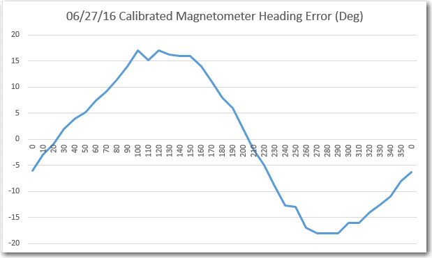
After Calibration Magnetic Heading Error

After Calibration Magnetic Heading Error

Comparing the above chart to the one from 6/19, it is clear that they are virtually identical.  I guess what this means is that, at least for the ‘free space’ case with no nearby interferers, calibration doesn’t do much.  Also, this implies that the heading errors observed above have nothing to do with external influences – they are ‘baked in’ to the magnetometer itself. The good news is, a sine function correction table should take most of this error out, assuming more accurate heading measurements are required (I don’t ).

In summary, at this point I have a working magnetometer calibration tool, and I have used it successfully to generate calibration matrix/center offset values for my Mongoose IMU’s HMC5883 magnetometer component.  After calibration, the ‘free space’ heading performance is essentially unchanged, as there were no significant ‘hard’ or ‘soft’ iron interferers to calibrate out.

Next up – remount the Mongoose on my 4WD robot, where there are  plenty of hard/soft iron interference sources, and see whether or not calibration is useful.


Magnetometer Calibration, Part III

posted 06/14/16

In my last post on the subject of Magnetometer Calibration, I described an entirely complete and wonderful calibration utility I wrote in C#/.NET using Windows Forms, an old version of devDept’s EyeShot 3D viewport library, and calls into the Octave libraries to execute a MATLAB calibration script.  Unfortunately, at the end of the project I discovered to my horror that my redistribution rights for the EyeShot libraries had expired some time ago, and re-upping them was prohibitively expensive – so I could use my masterpiece, but no one else could! :-(.

So, it was ‘back to the drawing board‘ for me.  I needed a (ideally free) 3D visualization capability with reasonably easy-to-implement  view manipulation (pan, zoom, rotate, coordinate axis, etc) tools that was compatible with C#/.NET.    After a fair bit of research, I found that Microsoft’s WPF (Windows Presentation Framework) platform advertised ‘full’ 3D visualization capability, so that was encouraging. Unfortunately, I had never used WPF at all, doing all my C#/.NET programming in the Windows.Forms namespace.  There were some posts that suggested the ability to place  a WPF 3D viewport window into a Forms-based app via a ‘WindowsFormsHostingWpfControl’ but after trying this a bit I decided it was going to be too hard to build up the required 3D viewport and associated view manipulation tools ‘from scratch’.  Eventually I ran across the 3D Helix Toolkit at  http://www.helix-toolkit.org/, and this looked very promising, but with the downside of having to re-create the entire application in WPF-land.  Actually, this appealed to me in a masochistic sort of way, as I would have the opportunity to learn two completely new packages/skills – WPF programming in general (which I had been ignoring for years in the hopes it would go away) and the feature-rich (but somewhat rough around the edges) Helix Toolkit.

So, off I went, reading as much as I could get my hands on about WPF and .NET visual programming.  It was initially very difficult to wrap my head around the way that WPF combines XAML with C# ‘code-behind’ to achieve the desired results.  At first I started out trying desperately to stick to my WinForms technique of drag/dropping tools onto a work surface, and then modifying properties as desired.  This worked up to a point, but I rapidly got lost due to the marked difference between WinForm’s ‘everything is a child of the main window’ and WPF’s hierarchical layout as described in XAML philosophy.  So, my first effort to build a WPF app isn’t very pretty, and  definitely violates any number of rules for WPF elegance!  However, the use of WPF and the Helix Toolkit made it reasonably easy to implement the ‘raw’ and ‘calibrated 3D views, and I had no real trouble porting the comm port and Octave implementation logic from my previous app to this one.  And of course, the entire object of the exercise was to create an app that could be shared, and the WPF version (hopefully) does that.

My plan for the future – at least with respect to the Magnetometer Calibration Utility, is to share the app within the robotics/drone community, and to continue to support  it as necessary to fix bugs and/or implement requested enhancements.  I also plan to set up a public GitHub repository as soon as I can figure out how to do it ;-).


Magnetometer Calibration, Part II

Posted 06/13/16

In my last post on this subject back in April, I had managed to figure out that my feeble attempts to compensate my on-robot magnetometer for hard/soft iron errors wasn’t going to work, and I was going to have to actually do a ‘whole sphere’ calibration to get any meaningful azimuth values from my magnetometer as installed on my robot.

As noted back in April, I had discovered two different tools for full-sphere magnetometer calibration (Yuri Matselenak’s program from the DIY Drones site, and Alain Barraud’s MATLAB script from 2008), but neither of them really filled the bill for an easy-to-use GUI for dummies like me.  At the end of April’s post, I had actually built up a partial GUI based on devDept’s EyeShot 3D viewport technology that I had lying around from a previous lifetime as a scientific software developer.  All I had to do to complete the project was to figure out how to integrate Alain’s MATLAB code into the EyeShot-based GUI and I’d be all set – or so I thought! ;-).

Between that last post in April and now, I have been busy with various insanities – competitive bridge, trying to develop a 3-point basketball shot, and generally screwing off, but I did manage to spend some time researching the issue of MATLAB-to-C# code porting.  At first I thought I would be able to simply port the MATLAB code to C# line-by-line.  I had done this in the past with some computational electromagnetics codes, so how hard could it be, anyway?  Well, I found out that it was pretty fricking hard, as in effectively impossible – at least for me; I just couldn’t figure out how to relate  the advanced matrix manipulations in Alain’s code to the available math tools in C#.  I even downloaded the Math.NET Numerics toolkit from  http://numerics.mathdotnet.com/ and tried it for a while, but I just could not make the connection between MATLAB matrix manipulation concepts and the corresponding ones in the Numerics toolkit – argghhh!!!.

After failing miserably, I decided to try and skin the MATLAB cat a different way.  I researched the Gnu Octave community, and discovered that not only was there a nice Octave GUI available for windows, but that some developers had been successful at making calls into the Octave dll’s from C# .NET code – exactly what I needed!

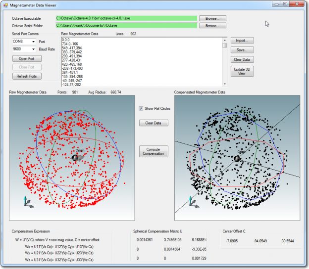
So, it was full steam ahead (well, that’s not saying much for me, but…) with the idea of a C#.NET GUI that used my EyeShot 3D viewport for visualization, and Octave calls for the compensation math, and  within a few weeks I had the whole thing up and running – a real thing of beauty that I wouldn’t mind sharing with the world, as shown in the following video clip.


Unfortunately, after doing all this work I discovered that my EyeShot redistribution license for the 3D viewport library had long since expired, and although I can run the program happily on my laptop, I can’t distribute the libraries anywhere :-(((((.

Ah, well, back to the drawing board!

Frank

(author’s note: Although I did this work back in the April/May timeframe, I didn’t post about it until now.  I decided to go ahead and post it  now as a ‘prequel’ to the next post about my ‘final solution’ to the magnetometer calibration utility challenge)