Tag Archives: battery pack

Wall-E2 Battery Charger PCB Part II

Posted 1 November 2017

In my last post on this subject, I described my efforts to create a PCB for the charging module in my wall-following robot(s).   I showed the hand-wired original, and the first (of three, so far) PCB versions. My circuit-checking skills are a bit deficient, so I keep finding ‘issues’ with the PCBs I received from Bay Area Circuits.   It’s not their fault as they produced PCB’s  exactly like I told them – apparently they don’t know about the RDM (Read Designer’s Mind) checkbox on their order form! 😉

In any case, the major problems I discovered on the first two revs are, kind-of, understandable for a PCB newbie like myself; I had the JST battery connectors switched, so Batt+ showed up on the PCB as Batt-, and the IRF-510 transistor holes were reversed as well.   A bit of cut-and-jumper work solved the first problem, and simply turning the transistor around solved the second one.   However, I really didn’t like leaving that as the ‘final solution’ so I splurged another $30 on a third rev with these problems fixed.   These boards have not yet arrived, so in the meantime I continued testing on the current setup.

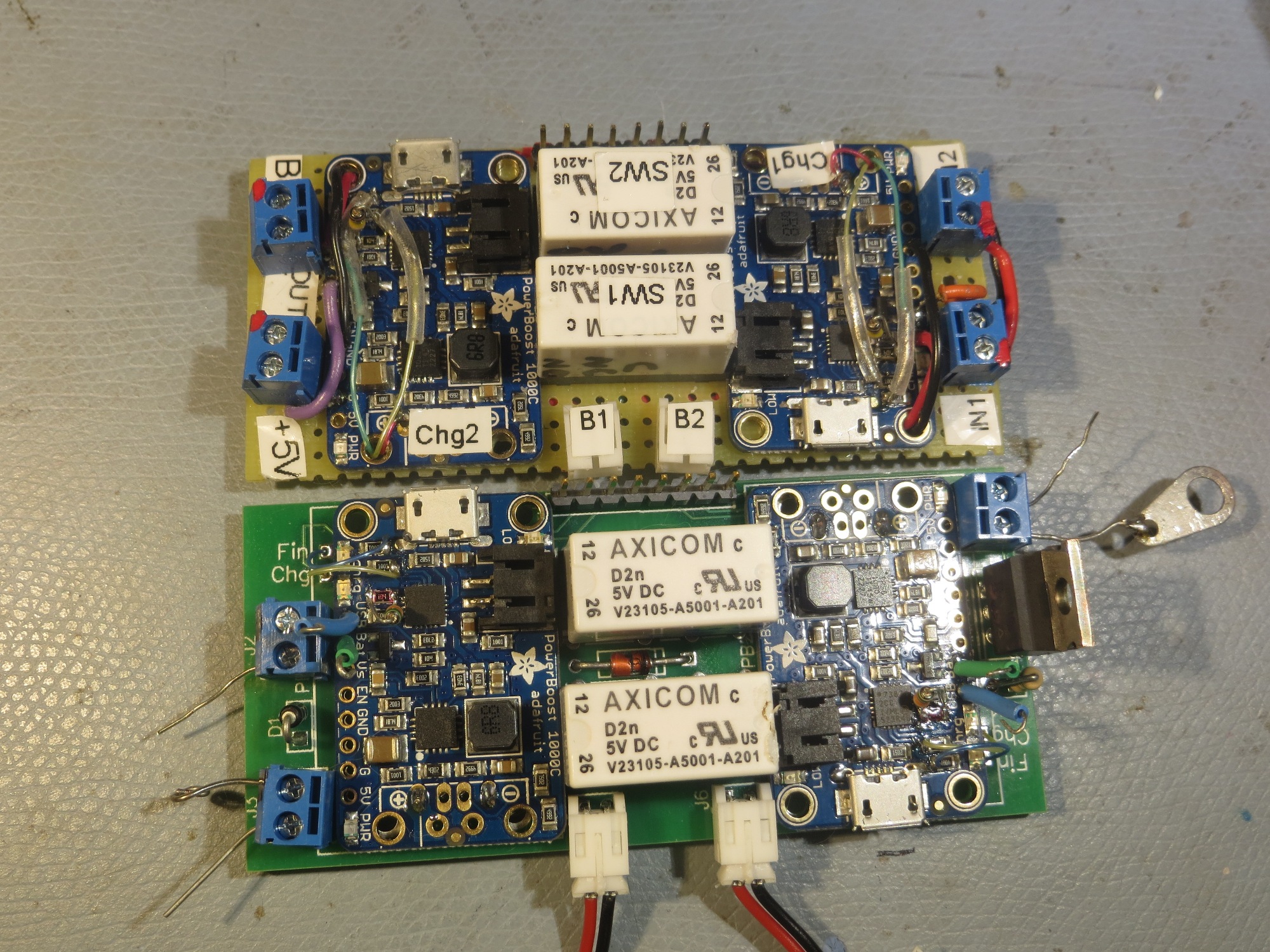
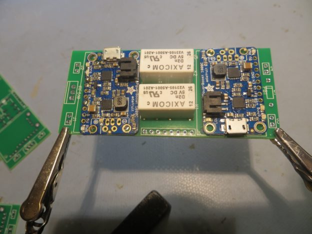
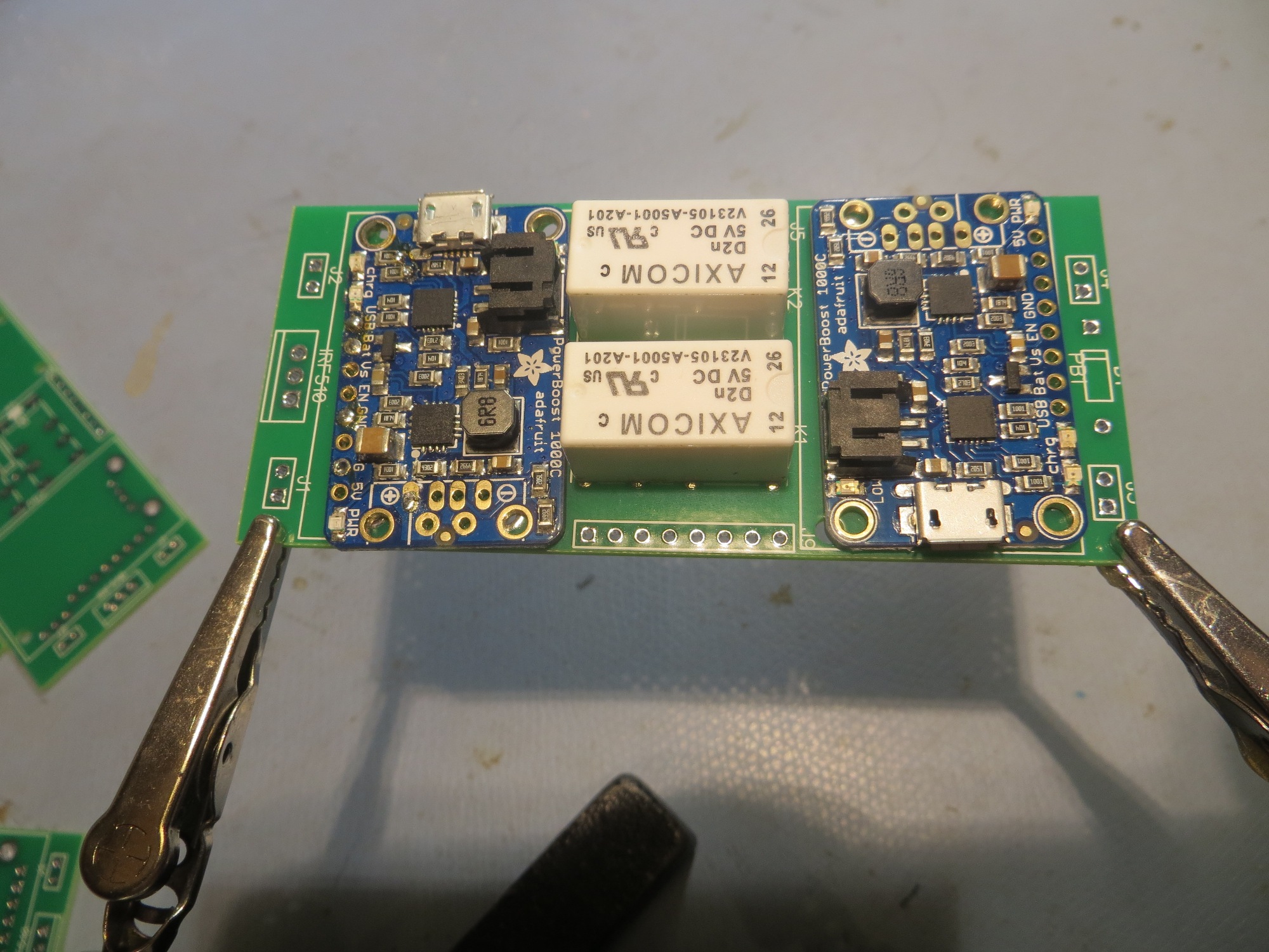
As the photo below shows, the finished and populated PCB has almost exactly the same dimensions as the hand-wired perfboard model.   Since the perfboard version had several components mounted on the wiring side, arriving at the same dimensions with everything on  one side is a definite plus!

comparison between the hand-wired perfboard version and the PCB

After getting the PCB populated, I did some electrical testing, and somewhere along the way I think I managed to damage the boost regulator chip on one of the PowerBoost 1000C modules.   And this is where I discovered my  next  major booboo – I had hard-wired the PB1000C’s to the PCB, and so now I couldn’t replace the damaged part without destroying the part, and probably the PCB too – oops!

07 December 2017 (Pearl Harbor Day) Update:

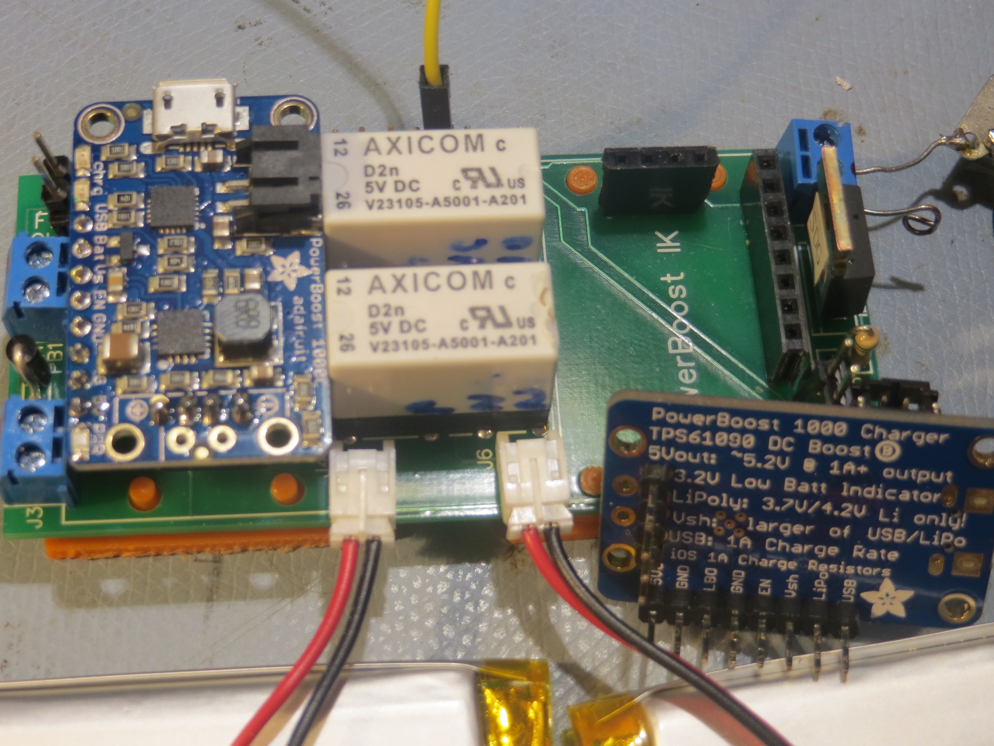
I received the latest (and hopefully, last!) batch of battery charger module PCB’s from Bay Area Circuits a week ago, but have been too busy with other things (mostly dealing with the new V3 robot chassis) to do much with it. So, today I started populating and testing the new charger module.   As I mentioned before, one of the bigger mistakes I made on the previous version was to hard-wire the PowerBoost 1000C’s onto the PCB, making it almost impossible to replace if it failed (and, as I learned from the Adafruit forums they can be easily damaged if they are powered up without a battery attached).   So, this time I soldered female headers onto the PCB and male headers onto the charger modules, making them easy to replace if needed.

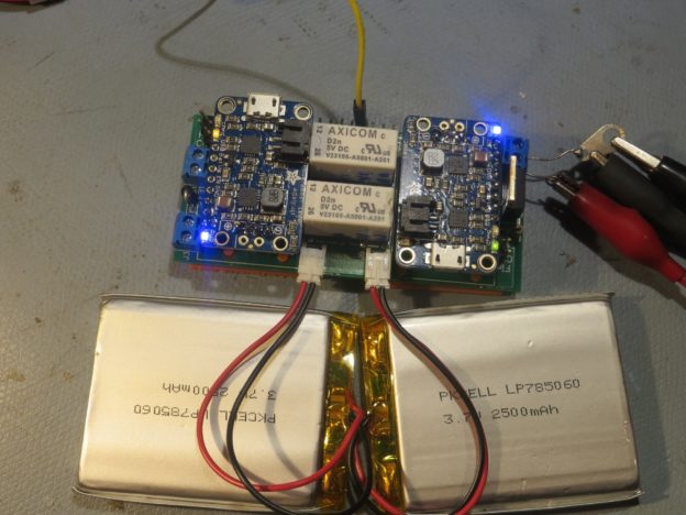
New charger module with some test batteries attached

Charger module showing PowerBoost 1000C header arrangement

The next step will be to test the module’s ability to manage the robot’s battery stack.   I plan to simulate the robot load with a 500 mA resistive load, and simulate the actual battery stack with the two smaller 2500 mAH batteries shown in the above photos.   I’ll simulate the robot with an Arduino, programmed to print out time-stamped readings of the robot power voltage (actually 1/3 of the robot power voltage, but what’s a scaling factor between friends?).

Stay tuned!


A New Chassis For Wall-E2, Part I

Posted 06 November 2017

Back in May of this year I came to the conclusion that I was never going to get my new four-cell battery pack (4ea 18650 3600mAH 3.7V LiPo cells connected as 2ea 7400mAH 3.7V stacks) and its companion charger module to comfortably fit into Wall-E2’s current chassis.   It all fits, but only with a considerable amount of pushing and shoving which has invariably resulted in damage to something – a connector, a wire, or something else vital.

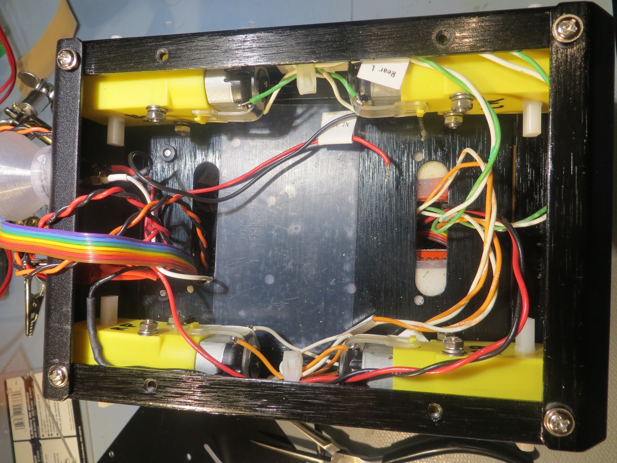
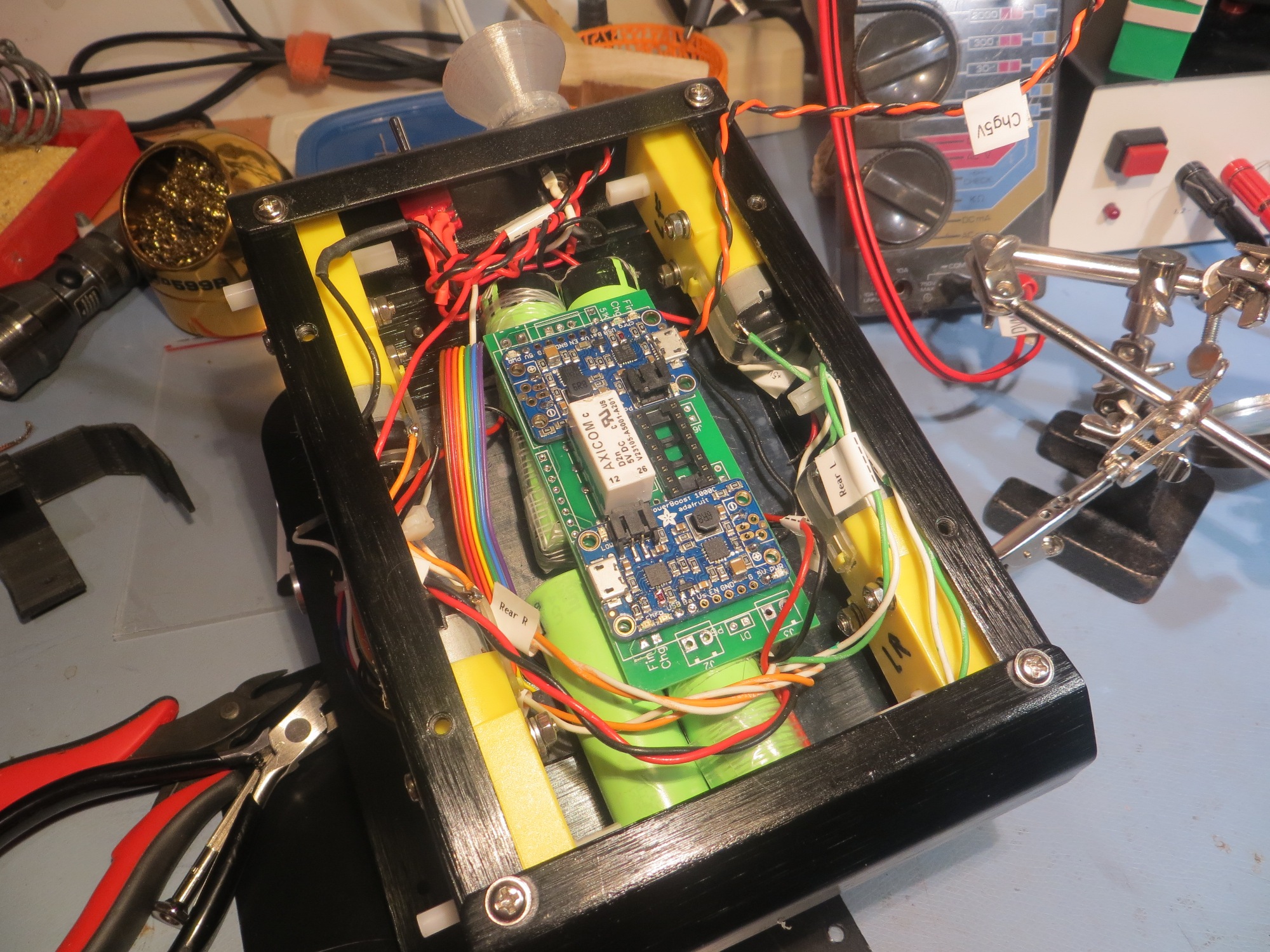
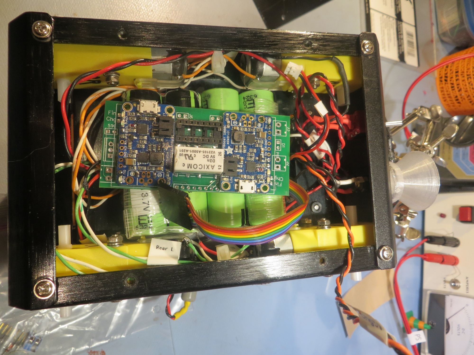
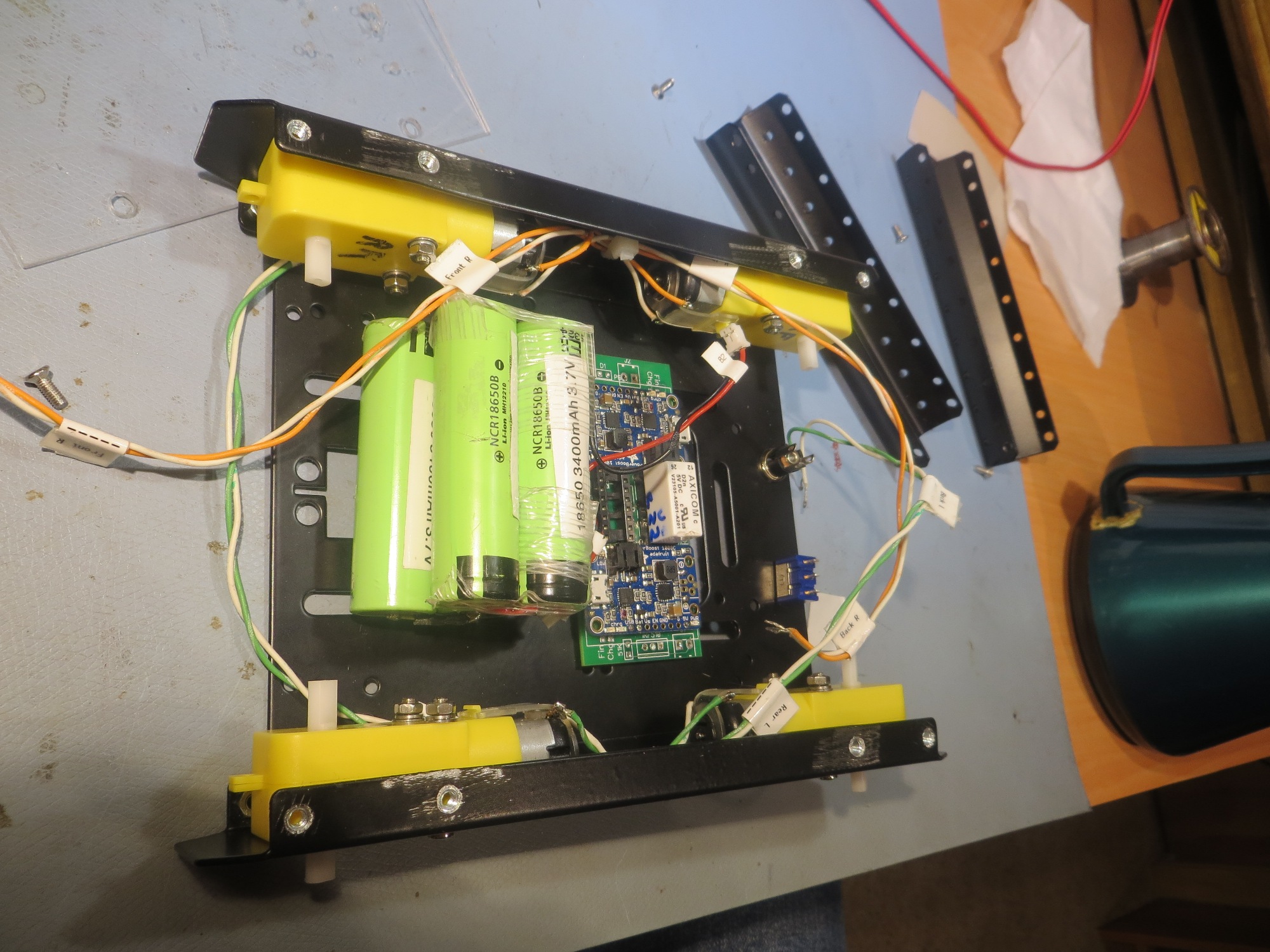
Bottom side view of 4WD robot showing battery packs and charging module

Bottom rear view of 4WD robot showing battery packs and charging module

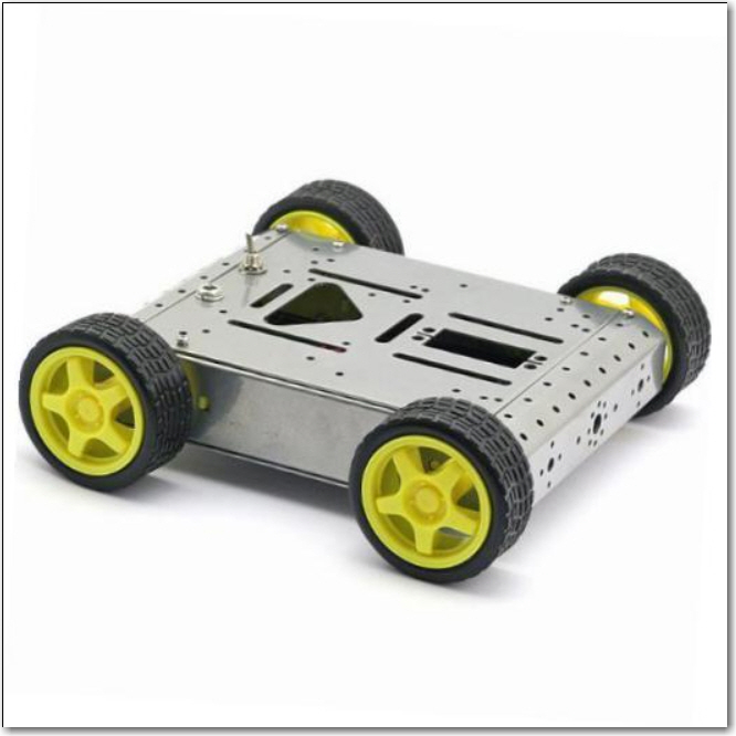
So, I spent some quality time online looking for a new, larger home for Wall-E2, and found this chassis

Lightweight 4WD Drive Aluminum Mobile Dolly Car Robot Platform for Arduino

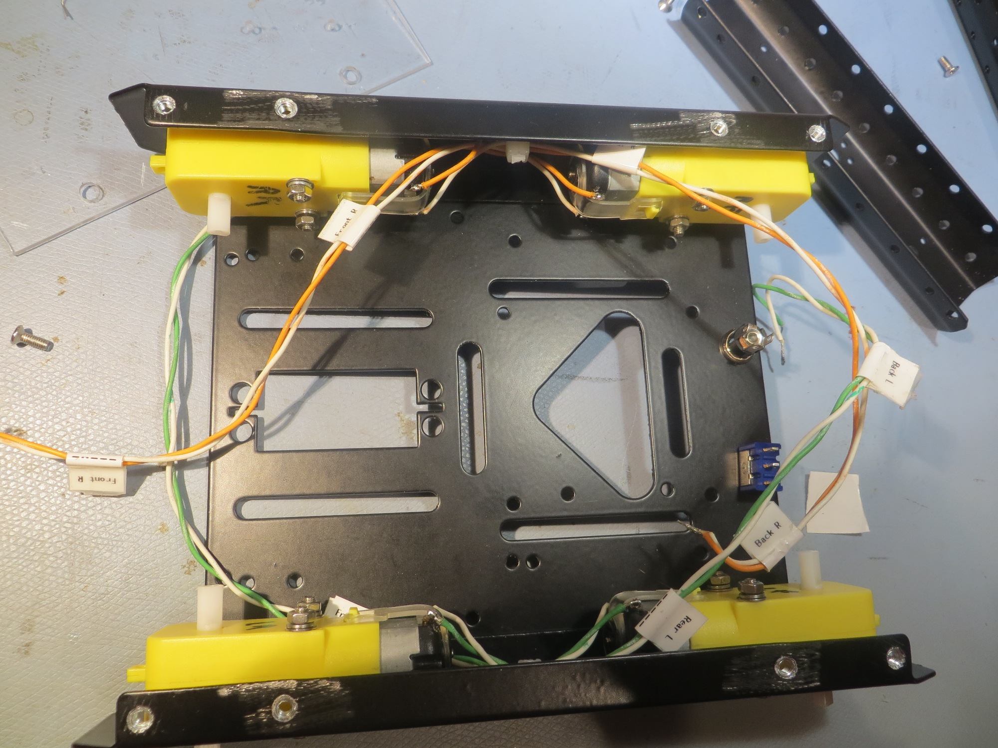
This chassis has an internal cavity width of about 14cm compared to 10.5cm for Wall-E2’s current ride.   This extra inch or so make all the difference in the world for comfortable installation of the battery pack and charger.

After getting this chassis on order, I basically forgot about it while I was working on the square-wave modulated IR homing project.   Then when my grandson Danny and his family visited in August, we dug out the kit and assembled it.   Danny wasn’t all that impressed with the quality (well, neither was I, but I didn’t expect all that much for $30 either).   After looking at both chassis (Wall-E2’s current ride and the new one), Danny suggested that maybe we could transplant the motors from the new chassis into the old one and get enough additional space from the different form factors to solve the battery problem.   At the time I pooh-poohed the idea, and put the new chassis back on the shelf to be forgotten again.

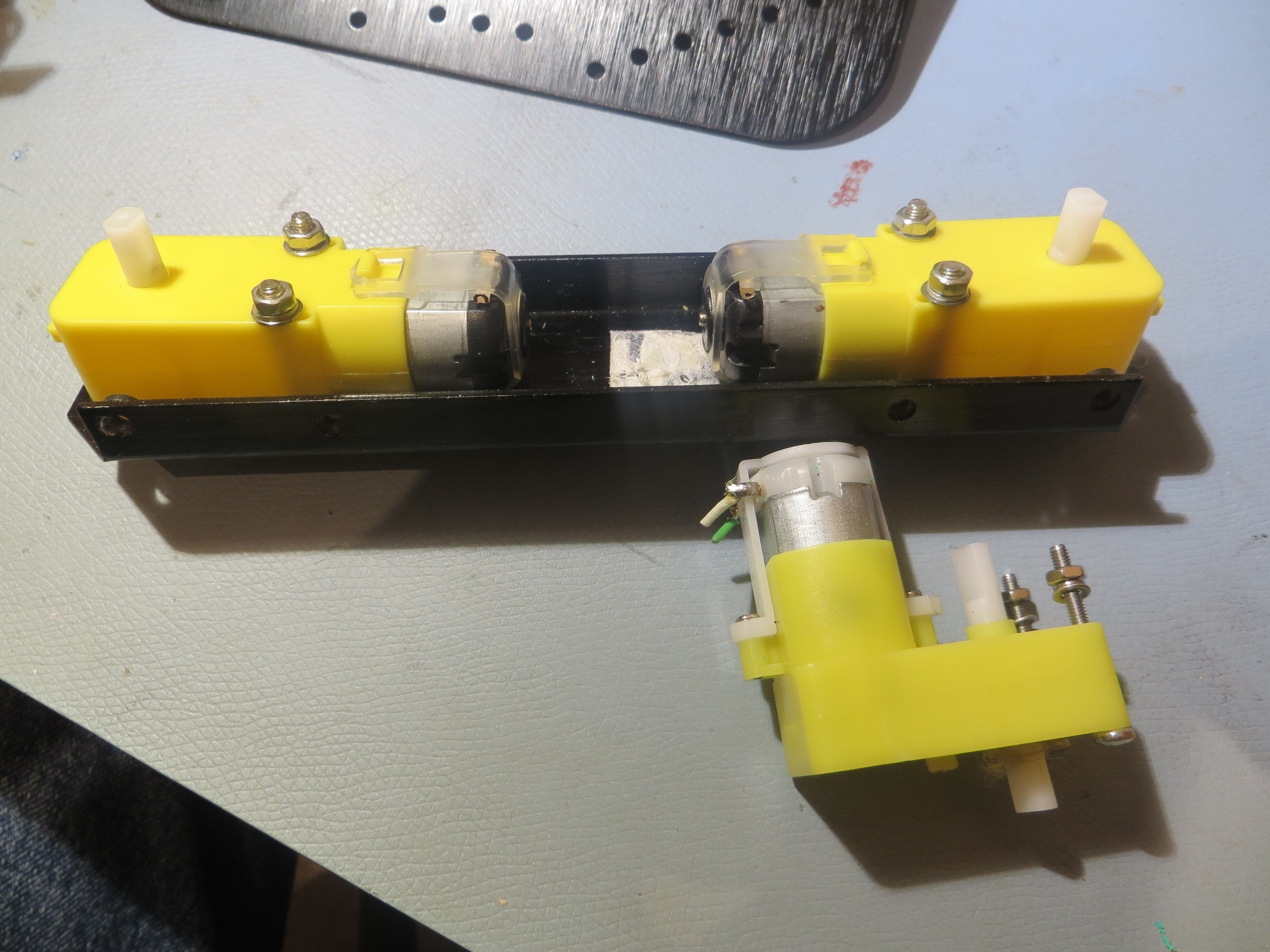
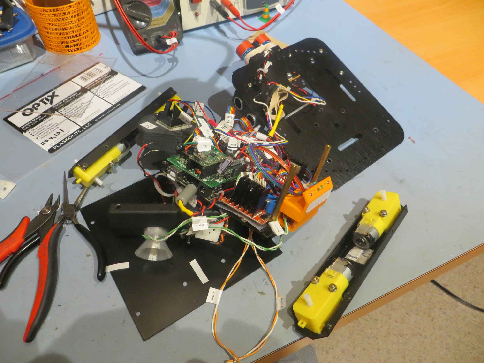
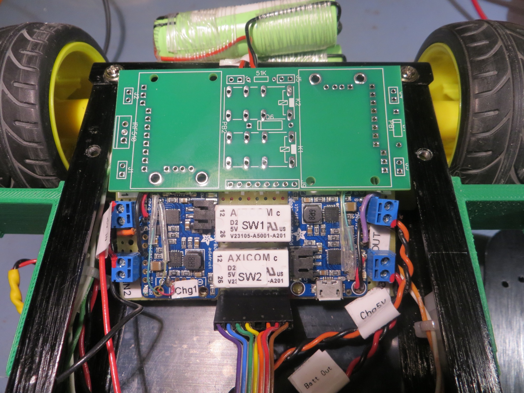
However, after finishing up the IR homing project last month, I decided I would actually try this trick and see what happened.   So, I laboriously swapped all four right-angle motors from the new chassis to the old one, and … RATS!!   As the photos below show, no real change in the available room for the charger/battery pack combination.   Well, at least I tried ;-).

So, now I’m back to swapping chassis (wow – plural form of ‘chassis’ is ‘chassis’ – go figure) instead of motors.

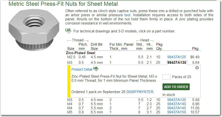
One of the major shortcomings in the new model was the cheapness of the threaded holes in the frame components.   The frame metal is so thin that instead of drilling and tapping the material, the holes were punched in a way that left the punched-out metal in the hole, and this material was tapped with the machine thread.   Needless to say, this lasted for about one (or fewer) screw/unscrew cycle before stripping out – bad design!.   Fortunately I knew how to fix this problem, with the help of McMaster-Carr.   I went to their site and ordered a bunch of press-fit nuts (also called PEM-nuts for historical reasons)

Press-fit nuts for my new robot chassis

In case you have never dealt with McMaster-Carr, they are incredibly quick.   I normally tell people that once I click on the ‘order’ button, I get up, walk to my front door, open it, and get hit in the chest by the shipped order! ;-).

Once I got the nuts, I replaced all the threaded holes on the new chassis with these wonderful little gadgets.   I used a #16 number drill to drill out the holes, and pressed the nuts in the new holes with a pair of cheap gas pliers – done!

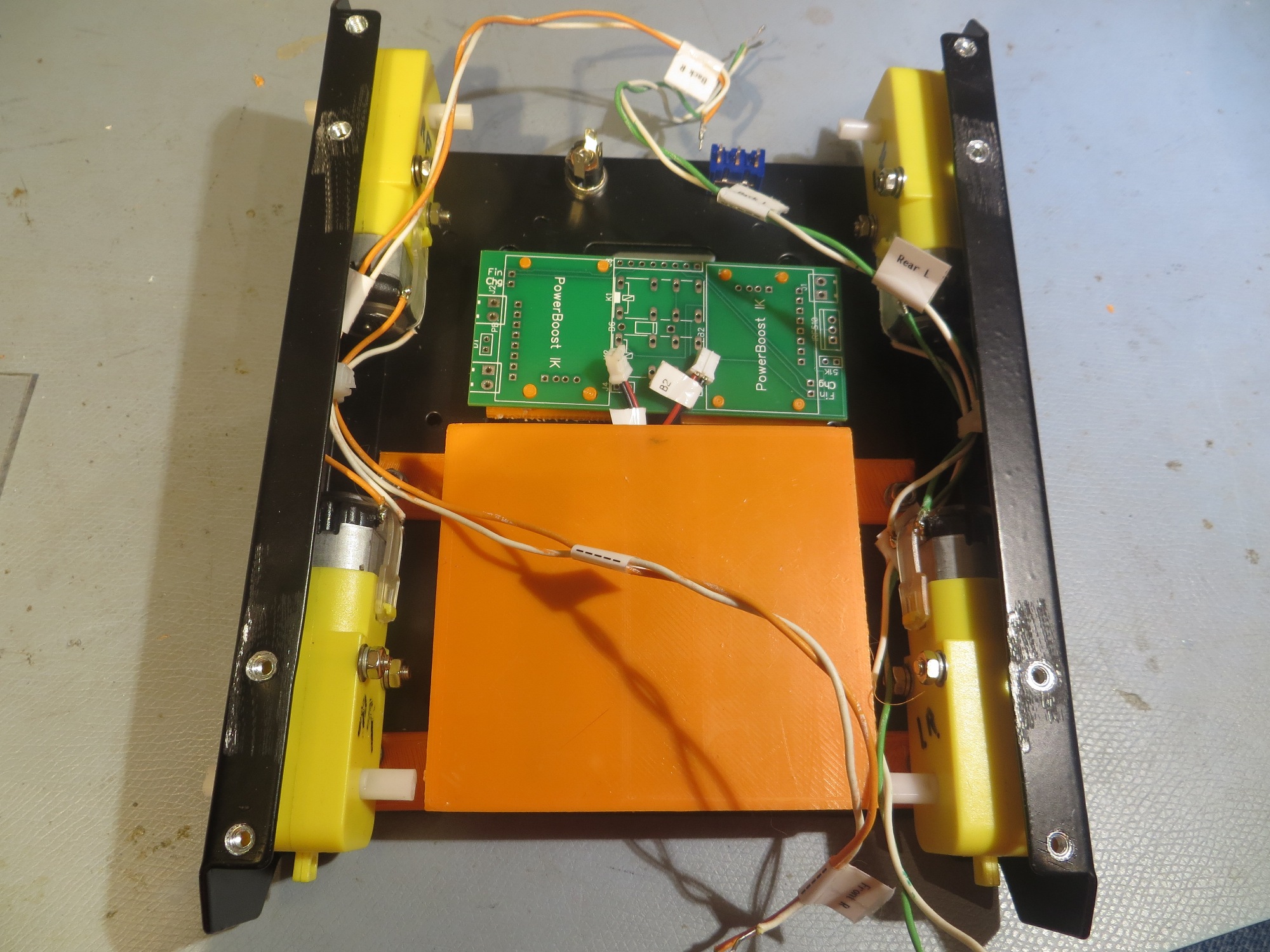
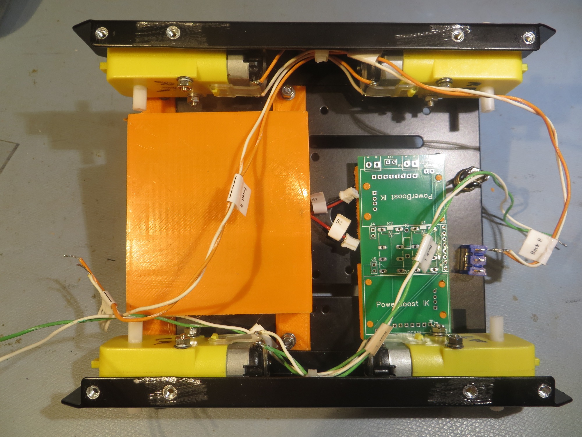
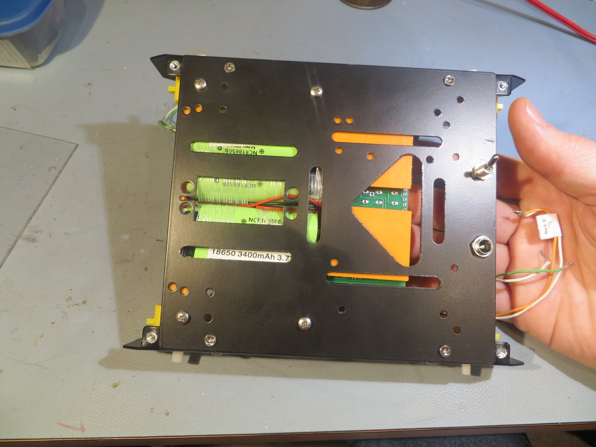
As seen below, there is a  lot more room in the new model

In fact, there is so much room that now I have to figure out how to keep the batteries and charging module from sloshing around in there.   Fortunately I have a fertile imagination, TinkerCad, and a 3D printer – so I designed and printed up a battery box, and a prototype stand-off design for the PCB, as shown below.

The next part of the puzzle will be to figure out how all that stuff (IR Homing Module, laser and ultra-sonic distance sensors, motor controllers and the main controller) is going to fit on the new chassis.

Stay tuned!

Frank


Wall-E2 Battery Charger PCB Part I

Posted 18 October 2017

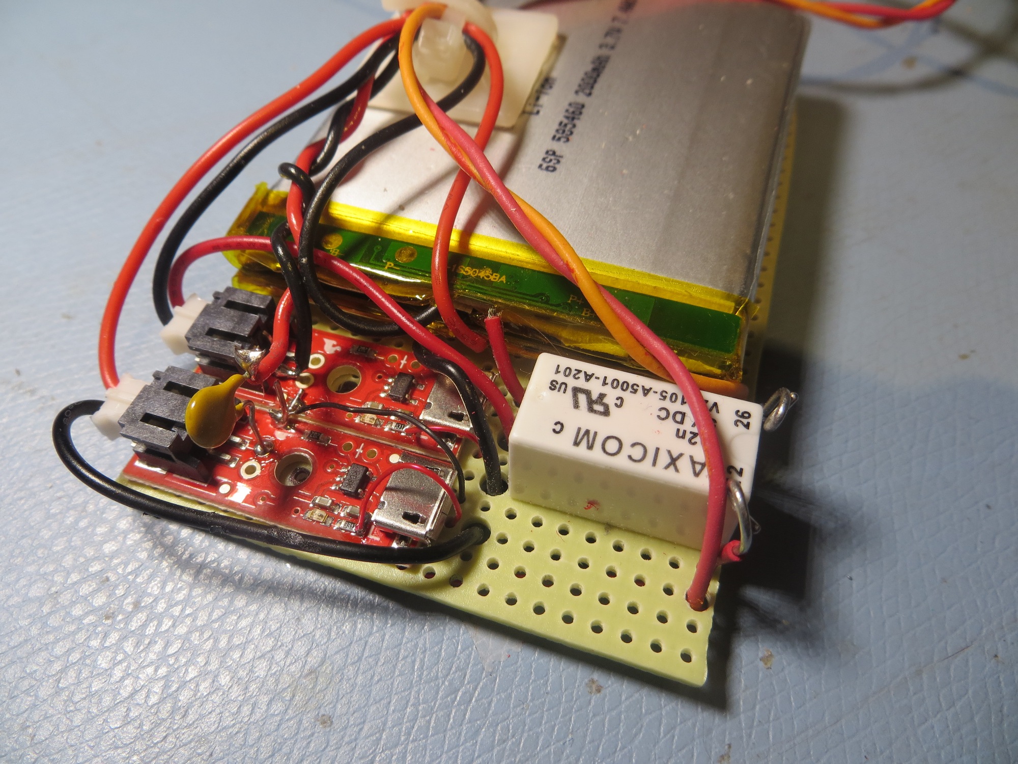
Wall-E2’s on-board battery system has gone through some major changes over the last three years or so. Back in October 2015 I implemented an on-board battery pack & charger using two Sparkfun boost chargers and two 2000 mAh LiPo batteries as shown in the following image.


Battery pack showing charging modules and switching relay. The tan capacitor-looking component is actually a re-settable fuse

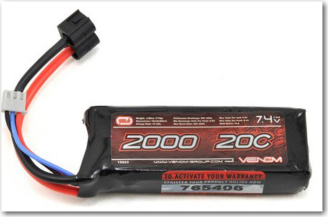
This was a technical success, but a practical failure; the LiPo cells just didn’t have the oomph to handle the high motor currents, and the single relay design had some problems as well.    So, in December 2015 I replaced the entire on-board battery system with a much higher discharge capacity RC battery, the GForce 2200 battery pack, as shown below

Current Wall-E2 battery pack

However, using this battery required that I physically disconnect the battery and connect it to an off-board charger for recharges, which meant I could never implement my idea of an autonomous robot.

So, about a year ago,  I re-implemented the on-board charging system, but with two significant changes; I used two 2-cell stacks of 3700 mAh 18650-style 3.7V li-ion batteries (specifically the NCR18650B cell) instead of the 2000 mA LiPo flatpacks, and two Adafruit PowerBoost 1000C chargers instead of the Sparkfun units.   I also added a second Axicom DPDT relay to solve the previous overvoltage issue.   The result is shown in the photograph below

Finished charging module connected to two 2-cell 3.7V battery packs

This system worked very well, and with the modifications  discussed in this post from last January (January 2017), I had a complete system for autonomous on-board charging.

This system has worked extremely well, but now I wanted to duplicate it for a planned upgrade to a larger robot platform, and I really wasn’t looking forward to hand-wiring another board. What I needed was a PCB, so I (or anyone else) could fabricate any number of charging modules without the PITA factor of a hand-wired perf-board implementation, so I decided to see If I could make a PCB using the free version of DipTrace.

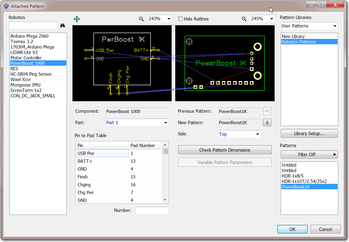
After fumbling around for a while in DipTrace, I soon realized that in order to do a good job with a PCB design, I needed a component and associated PCB pattern for the Adafruit PowerBoost 1000C, and AFACT, none existed – at least not in a form compatible with DipTrace.   So, after some more fumbling around, I came up with the following model for the PB1K

DipTrace component model for the Adafruit PowerBoost 1000C

Creation of this component was complicated by the fact that I needed ‘flying lead’ connections to the ‘charging’ and ‘finished’ LED drivers on the PB1K module – signals that aren’t exposed to the outside world.   Eventually I hit upon the idea of adding a couple of ‘off-board’ pads (shown above at the lower left corner of the pattern), and assigning them to the ‘Finish’ and ‘Charging’ functions of the component layout. The ‘Chg Pwr’ signal already existed on the breakout header as the ‘Power’ signal, so I didn’t need anything for that.   These modifications allowed me to integrate the PB1K module into the charger schematic and the PCB layout using the normal DipTrace project work flow.

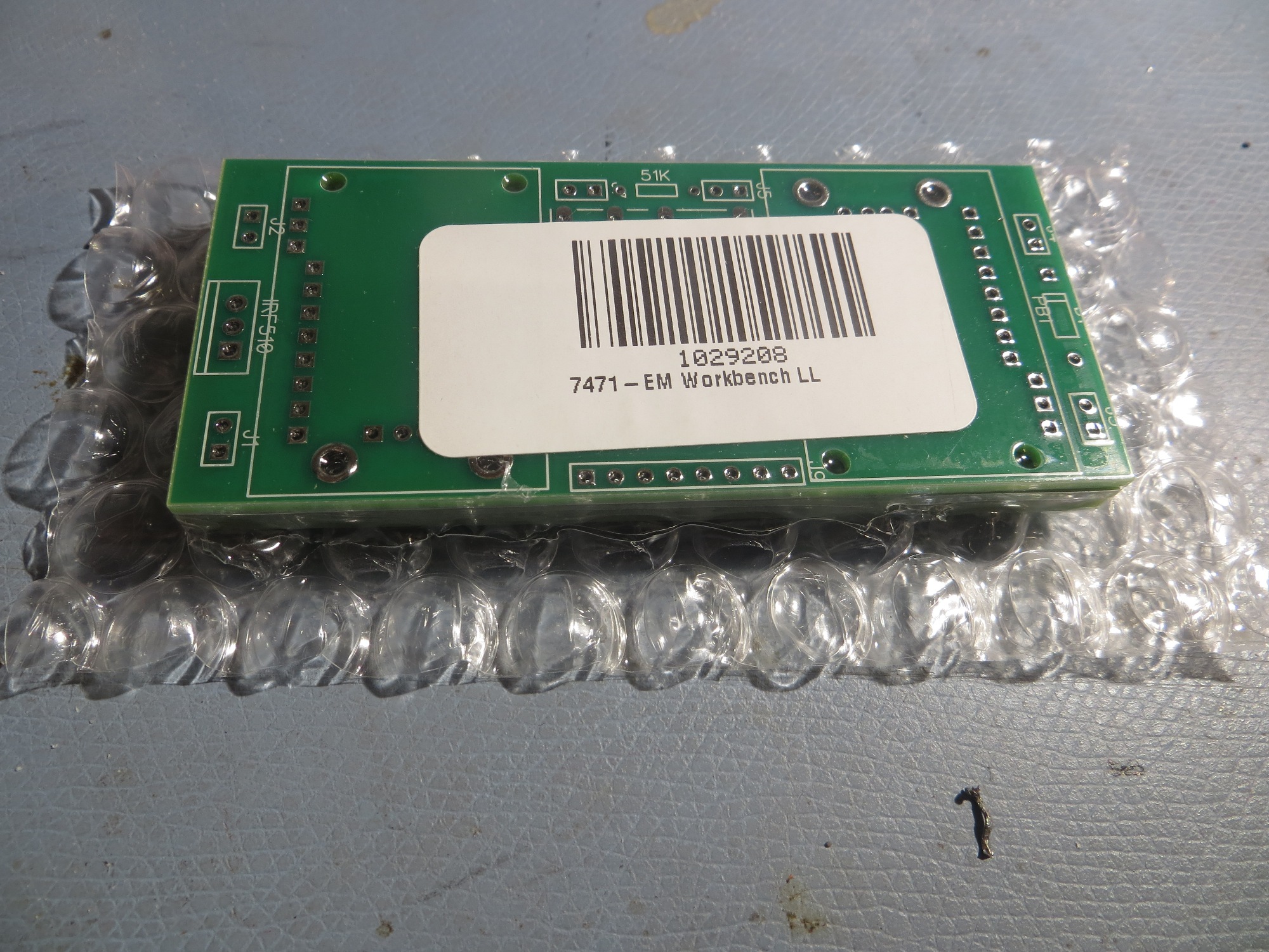
After getting what I thought was a successful layout, I clicked the ‘Order PCB’ button in the PCB editor, and ordered their minimum of two PCBs for $30 + shipping (I actually received 4ea PCBs so it was an even greater deal than normal!).

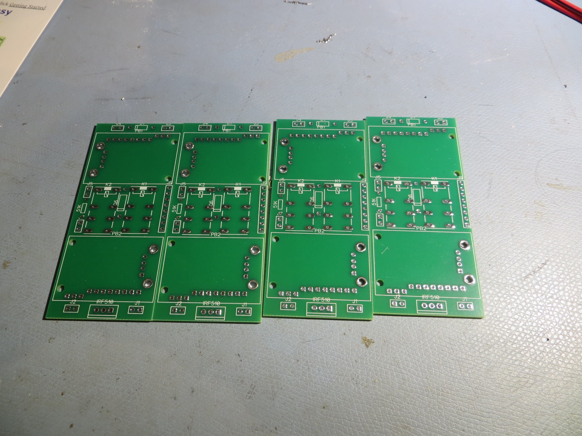
PCBs as received from Bay Area Circuits – nice packaging!

Four PCBs for the price of two – cool!

Test run to populate PCB with actual components

Size comparison between PCB and hand-wired versions. First iteration of PCB is slightly larger

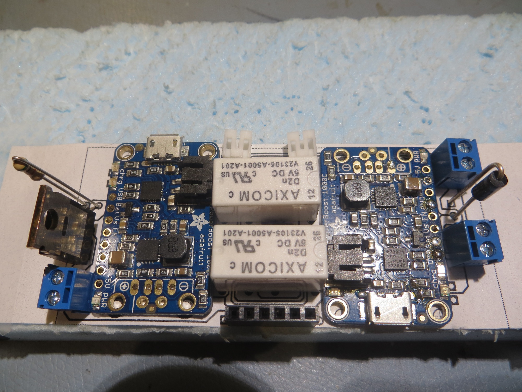
After inspecting the PCBs, I realized I had screwed up on a couple of items.   The pad pattern for the two-wire terminal blocks wasn’t correct (too small), and at least one of them was reversed – oops!   In addition, a couple of PCB traces weren’t correct. So, it was back to the drawing board (literally) for a ‘version 2’ PCB.   On this iteration I learned a good bit more about DipTrace’s schematic/component/pattern relationship, so I felt like I was getting at least some value out of my screwups.   After removing a superfluous 2-wire terminal block and moving a couple of parts around, I was able to make the V2 PCB smaller than the original hand-wired model.   This time I remembered to use DipTrace’s verification routines, and this allowed me to catch some additional problems that had made it through into V2.   In addition, I used DipTrace’s print facility to print out a 1:1 PCB layout on paper, so I could double-check parts placement with real components, as shown in the following photo

Second iteration PCB printed at 1:1 scale on paper for component fit testing

So, many hours and a couple of iterations later, I have what I believe is a successful PCB implementation, and I sent off a new order to BAC.    As usual, I wound up spending  far more time designing the PCB than I ever would have in making a second hand-wired unit for the new robot, but where’s the fun in  that?

Stay tuned

Frank


Wall-E2 Charging Station Design, Part V

Posted 18 Dec 2016

The new charging system for Wall-E2 consists of three major parts:

  • The two 3.7V Li-Ion battery packs and battery chargers (one charger for each battery pack)
  • The contact array that connects the charging platform  to the chargers.
  • The charging platform and charging power supply

I have spent the few days  or so working on the first two items above, building up the battery pack and charging circuit for Wall-E2, and working out the details of the contact array for connecting Wall-E2 to the charging platform.

Charging Module:

This is actually the third time I have attempted a charging system for a  7.4V Li-Ion battery pack consisting of two 3.7V cells.  The first one was for my original Wall-E, and it is still cooking along.  The second one was for Wall-E2, and it didn’t go as well.  After all the work of building up the module and tucking it into the robot, I discovered that the system just wasn’t robust enough for Wall-E2’s higher power requirements, so I wound up going with a high-current RC battery and an external charger.  This wasn’t really satisfactory either, as the battery pack was just too big and awkward, and having to physically disconnect the pack from the robot to charge it was a real PITA.  Plus, I still harbored the  desire to make Wall-E2 more human-independent by giving it the capability of recharging itself.  So I made another run at the dual-pack charging universe, and this time I found an article by the Adafruit guys  about a ‘simple balance charger’ using two of their Li-Po chargers and a manual 3PDT switch.  This article very closely matched the charger setup I had used previously,  except for one extra pole on the switch.  In the Adafruit circuit, this third pole was used to switch the positive side of the upper 3.7V pack from the load  to the upper charger. My previous designs didn’t have this switch, and on closer examination, I realized that without this third pole, the upper charger might see the entire 7.4V on its output port – oops!  The reason for this is that the chargers aren’t truly isolated from each other – they share a common ground, and when the circuit is in  series (RUN) mode, the upper charger’s plus output is still tied to the upper battery’s positive terminal, while its negative output is still at ground.  This puts the entire  7.4V across the upper charger – a  BAD thing!

So, I needed a third pole, but although small 3PDT manual switches are easy to find, small/compact 3PDT relays are not.  In my previous designs I had used the very nice Axicom V23105 2PDT telecom  relay, but 3PDT relays in the same form factor were nowhere to be found – grrr!  So eventually I decided to use  two of the Axicom relays and gang the coils to get a 4PDT relay, one pole of which would go unused.  Also, learning from previous mistakes, I made sure I could easily remove/replace the battery packs and the chargers if necessary.  The final charger schematic is shown below, along with some images of the finished charger module.
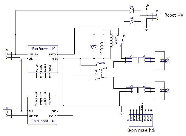
Dual cell balance charger. Note the two Axicom relays ganged to form the required 3PDT switch
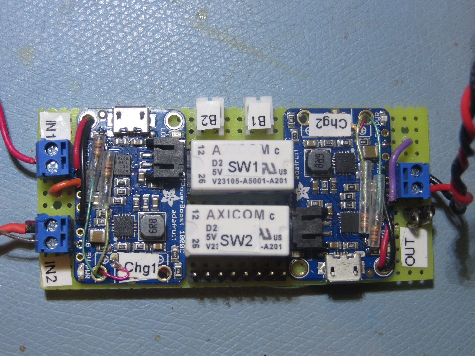
Closeup of the completed charging module. Note the two Axicom relays used to implement a 3PDT switch
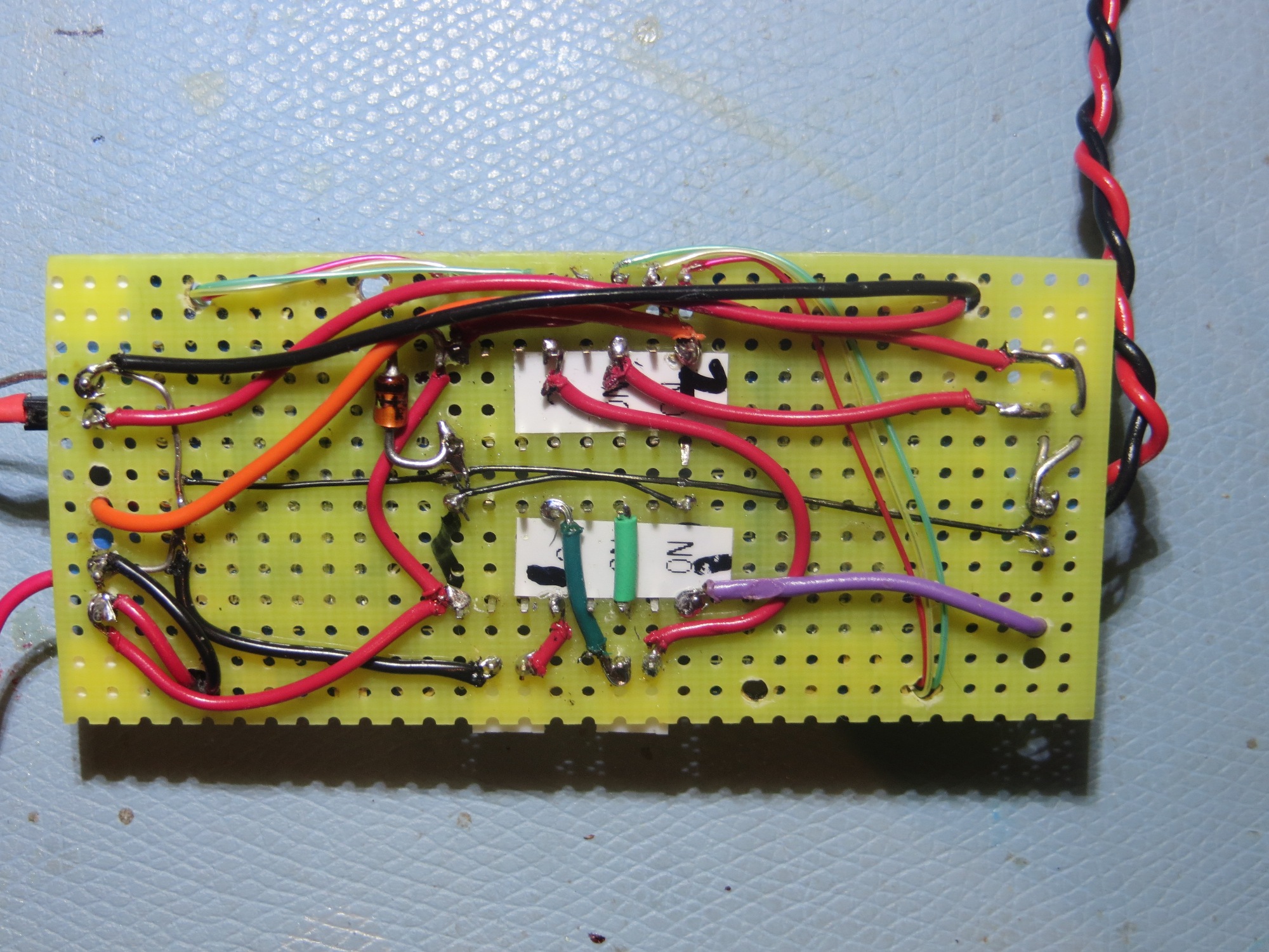
bottom wiring layer of charging module
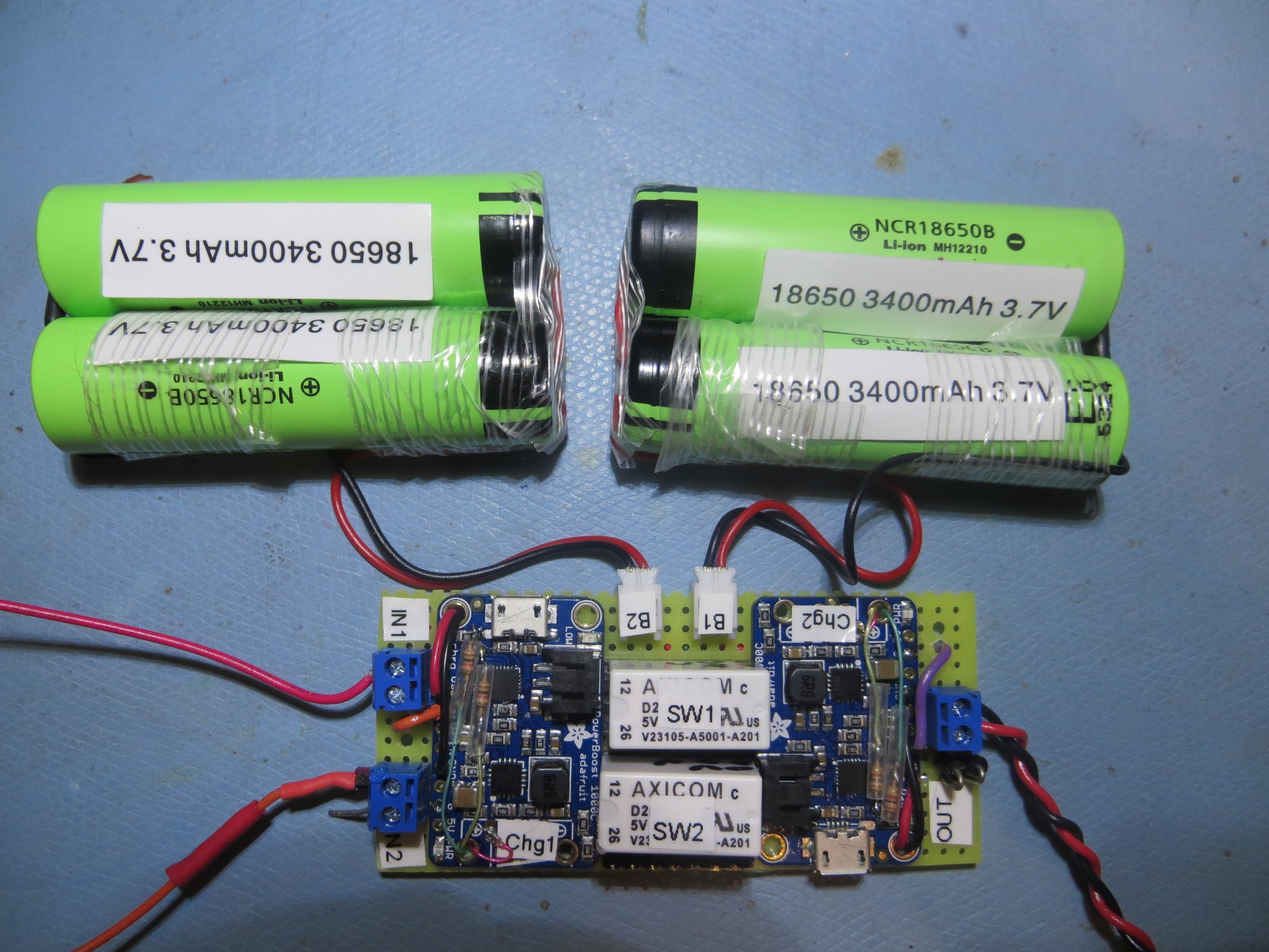
Finished charging module connected to two 2-cell 3.7V battery packs
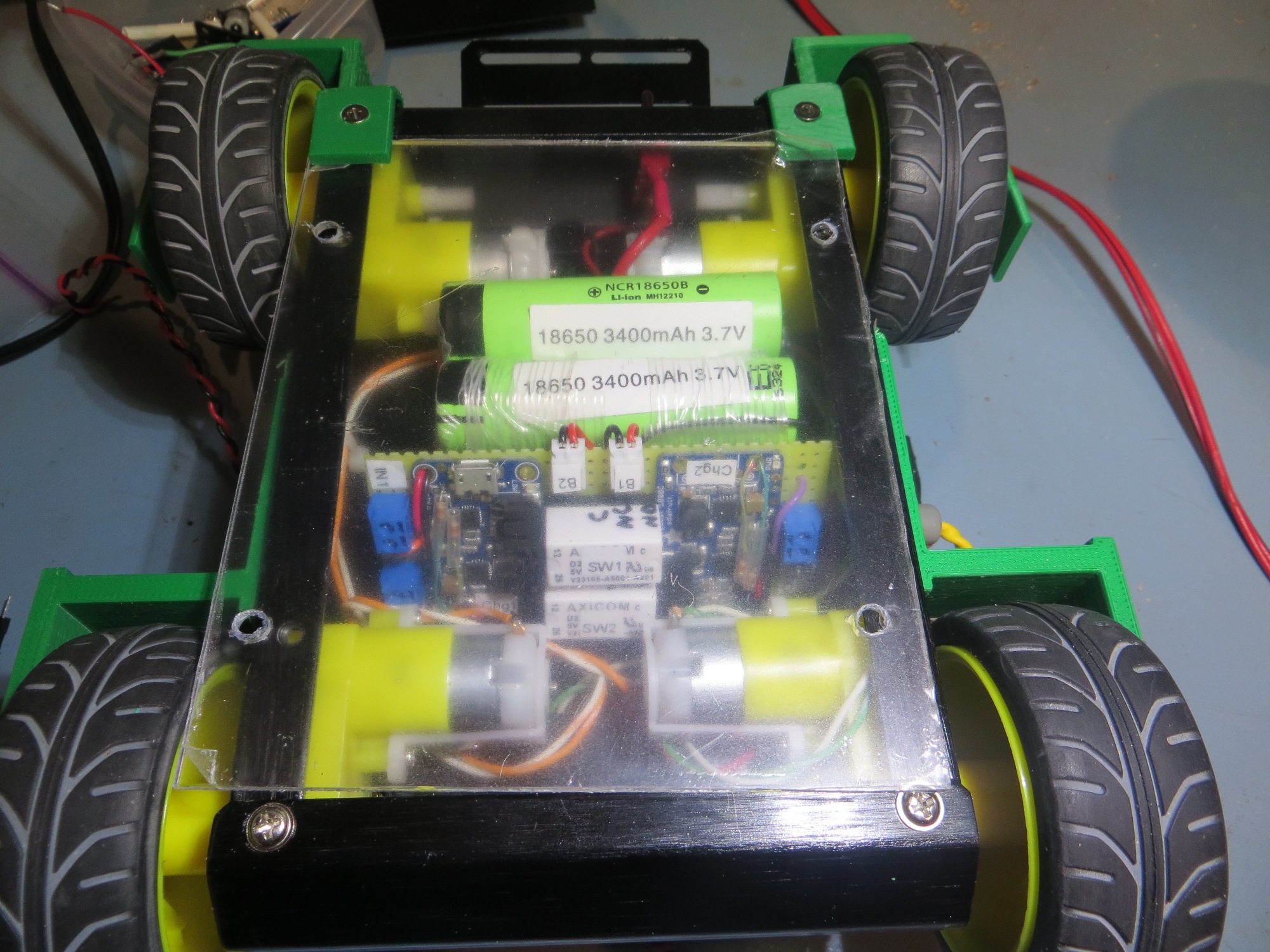
Bottom rear view of 4WD robot showing battery packs and charging module

Signal/Power Contact Array

The next challenge was to figure out how to connect the robot to the charging station.  In addition to supplying +5V to the two chargers, I wanted to bring out the power, charging and charge-completed  status signals from both.  This requires a total of 8  contacts ( 6 status signal lines, +5V in, and GND).  I also decided to bring out the power line to the robot, for a total of 9 contacts.  The idea here is to place contact strips on the bottom of the robot, which will make contact with spring-copper sliding contacts on the charging platform.  I played with a number of contact layouts, but ultimately decided on a straight-line array of contacts due to space restrictions in the robot.  In the image below, the contact array layout is shown, with the ‘Pwr LED2’ position partially implemented.
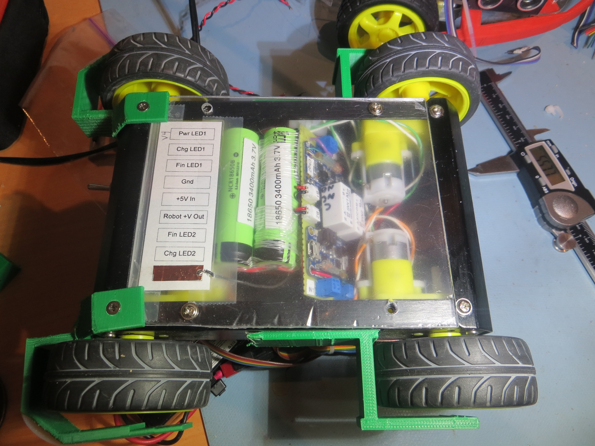
 

Bottom side view of 4WD robot showing  contact array layout  with the ‘Pwr LED2’ position partially implemented

Some time ago I purchased a length of beryllium-copper finger stock used for fabricating EMI gaskets, with the intention of using the individual fingers as contacts for the charging station.  In order to do this, I needed a way of capturing each finger in the top surface of the charging station.  I went through several iterations as shown below
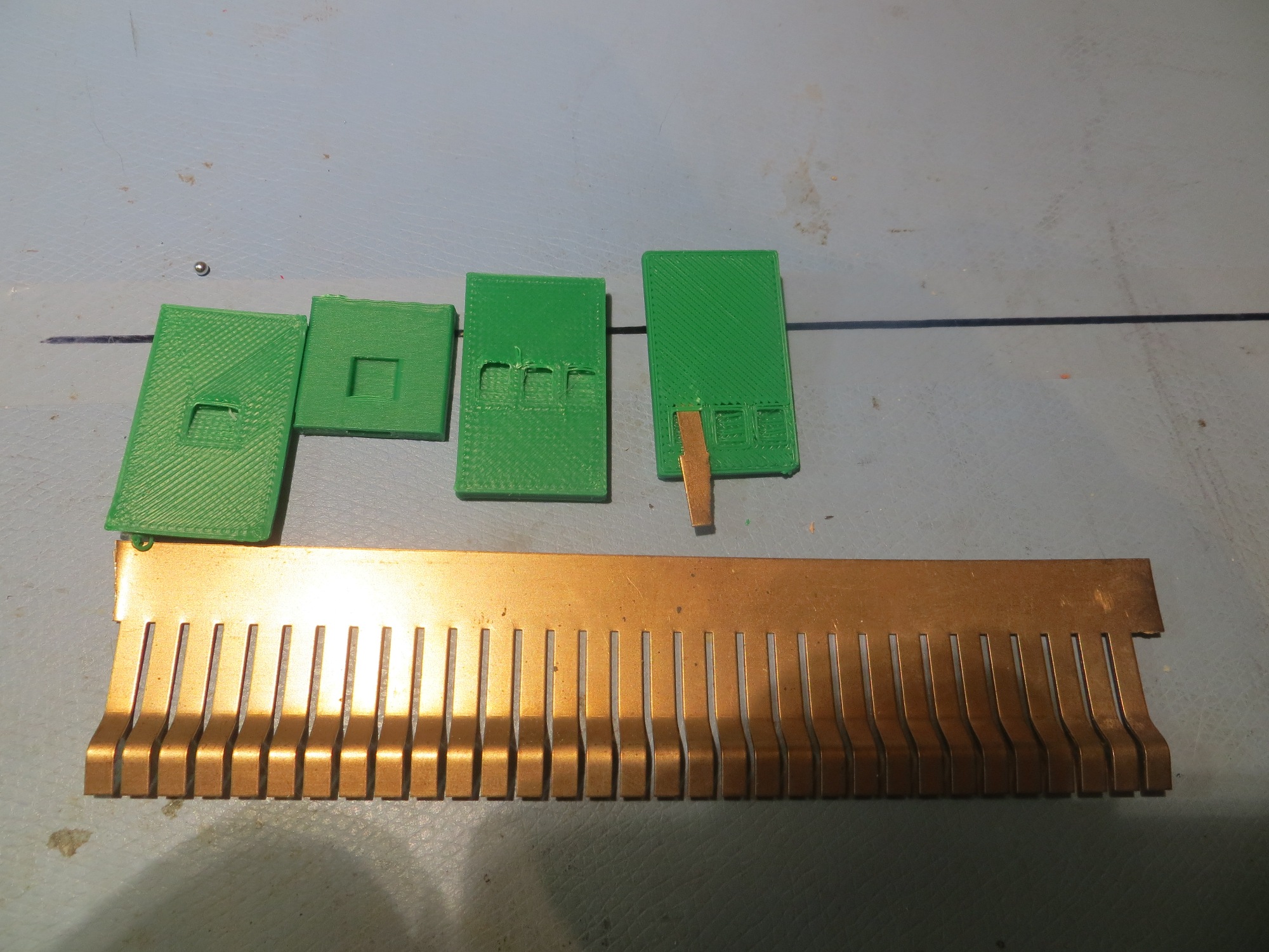
After playing around a bit with  a single contact finger and the contact arrangement shown above, I realized that a small misalignment between the robot and the charging platform could cause a finger to bridge two contacts or even connect with the adjacent circuit.  So, I went back to Visio and redesigned the contact layout, as shown below
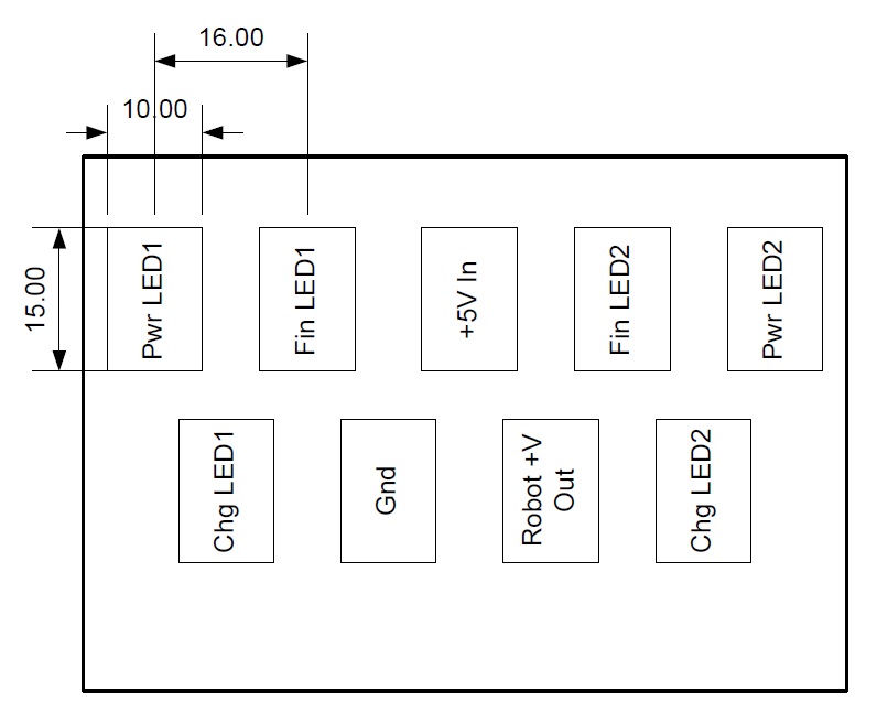
 

two-row contact layout.  Contacts are 15x10mm with 16mm center-center spacing

As shown in the following photos, this is a much more robust arrangement in terms of contact mis-alignment protection, at the cost of taking up more space on the bottom of the robot

Contacts just prior to engaging
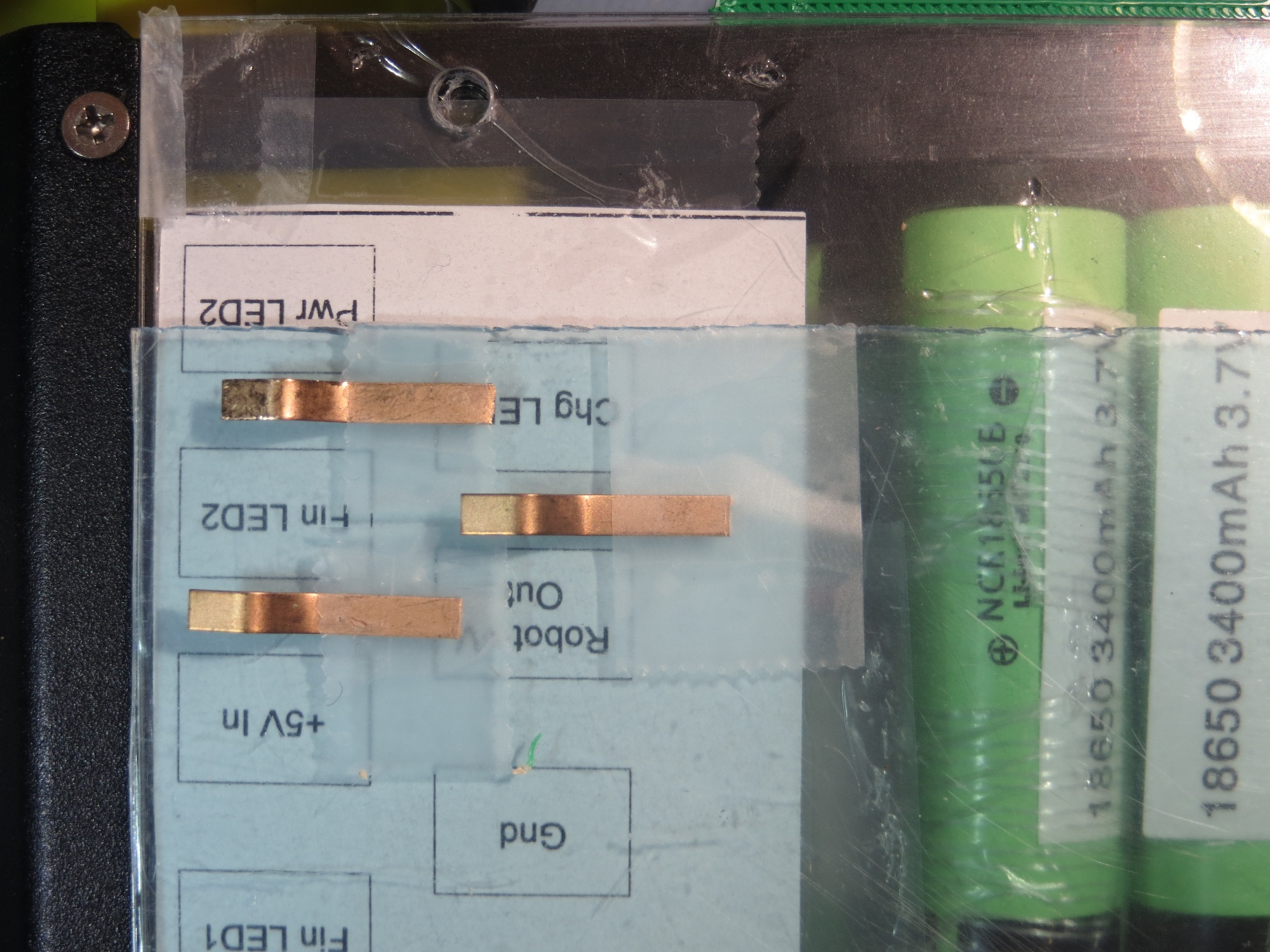
Contacts mis-aligned low
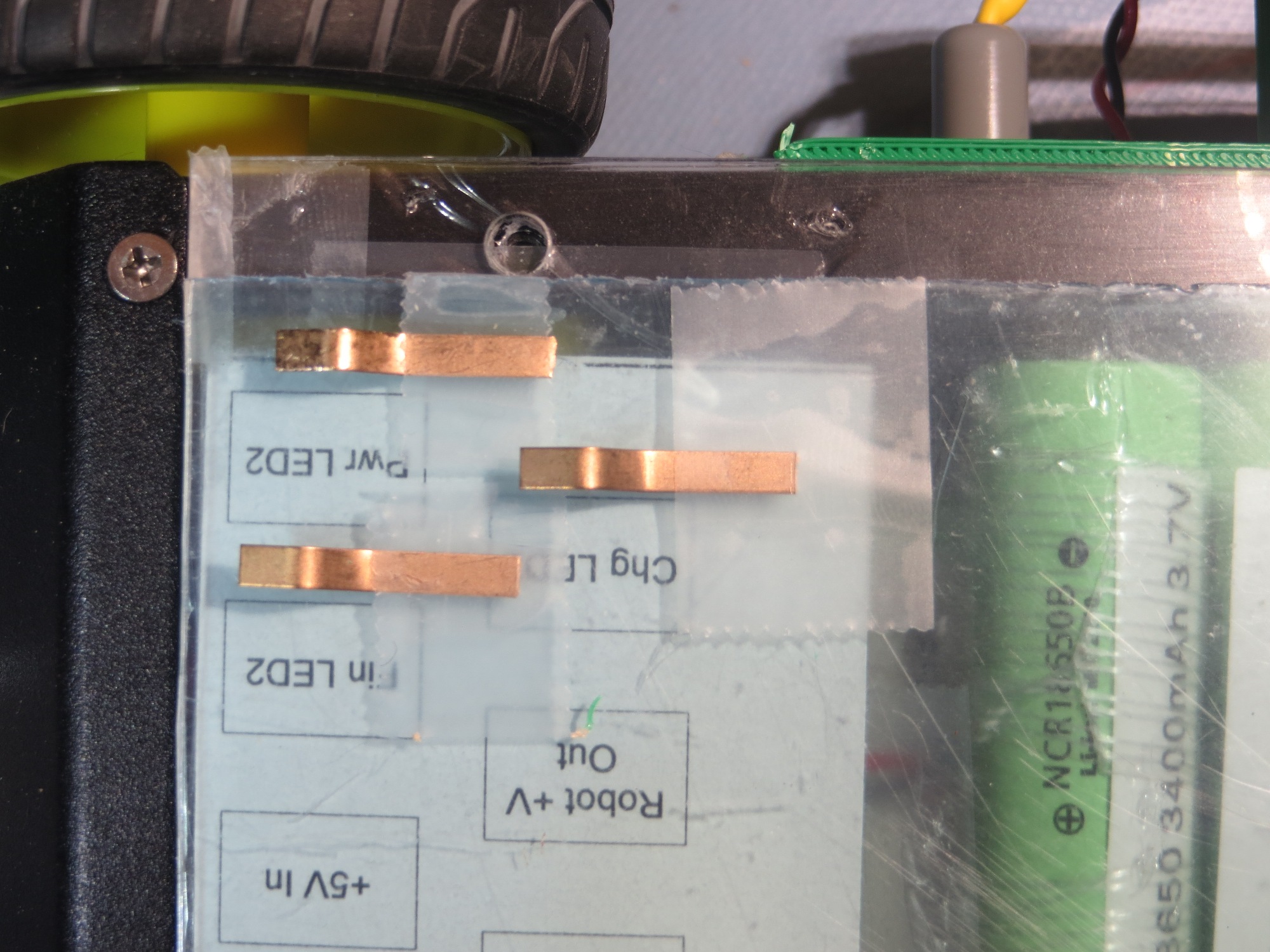
Contacts mis-aligned high
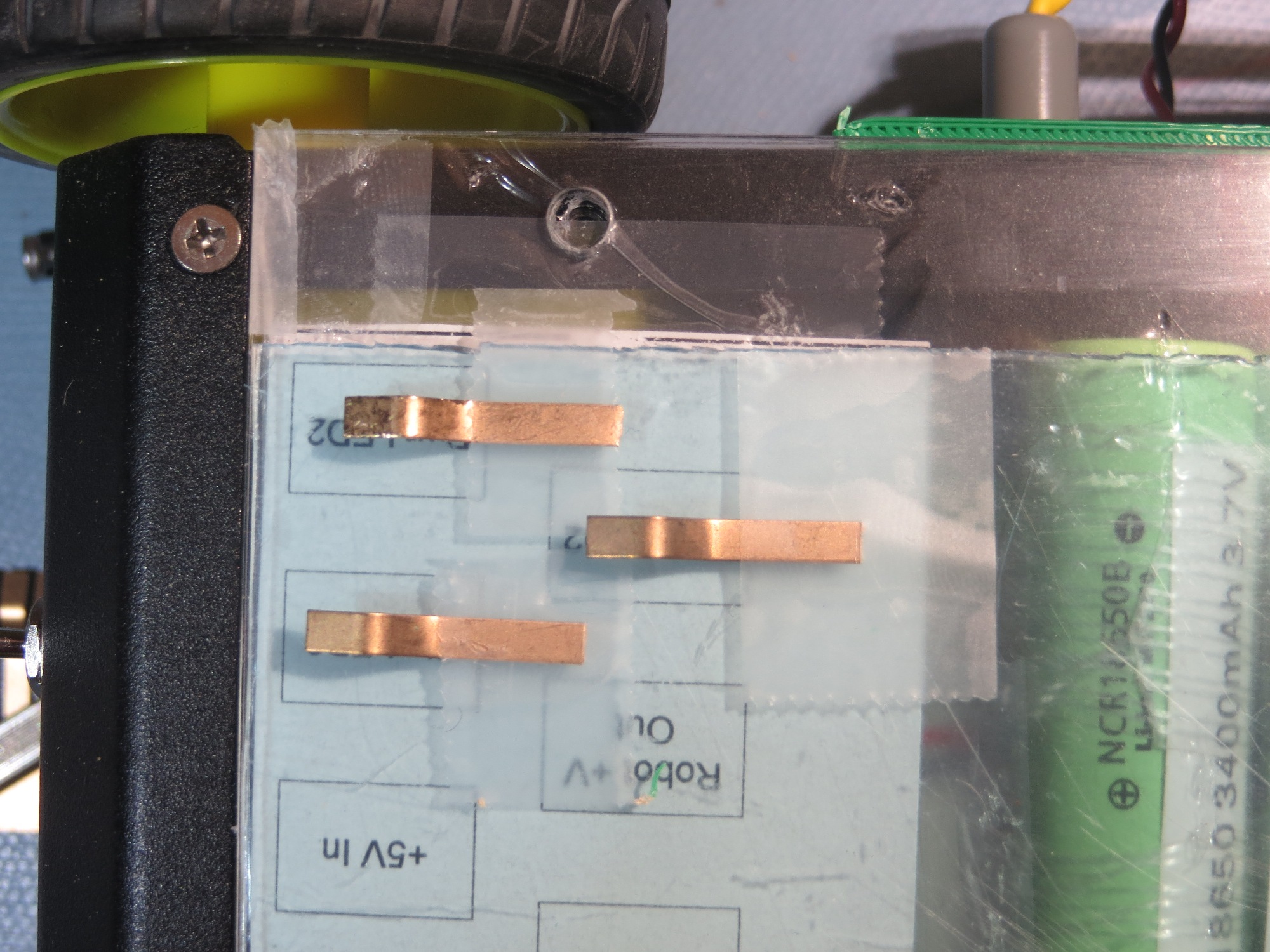
Contacts in the fully engaged position
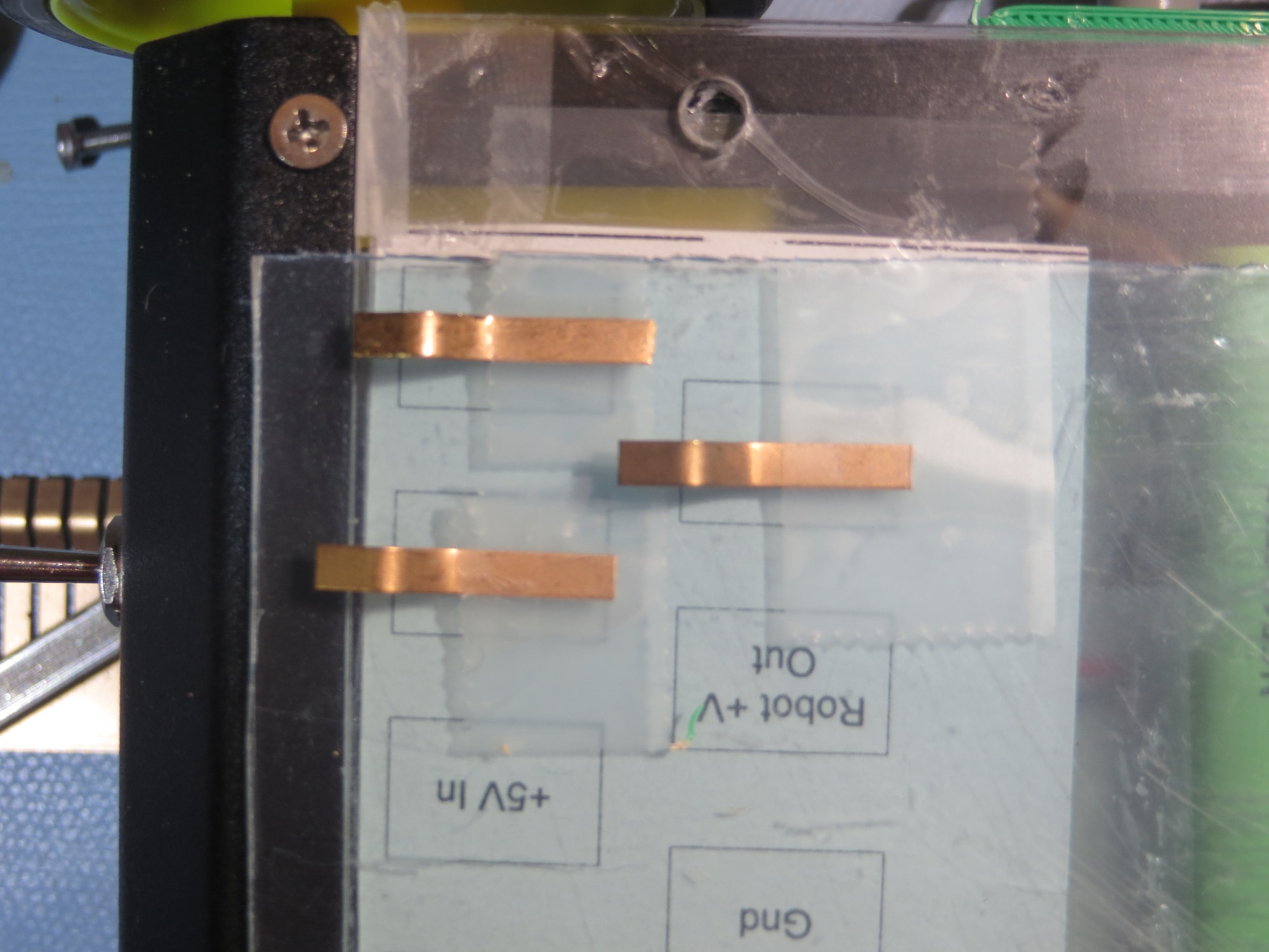
Contacts just before engaging
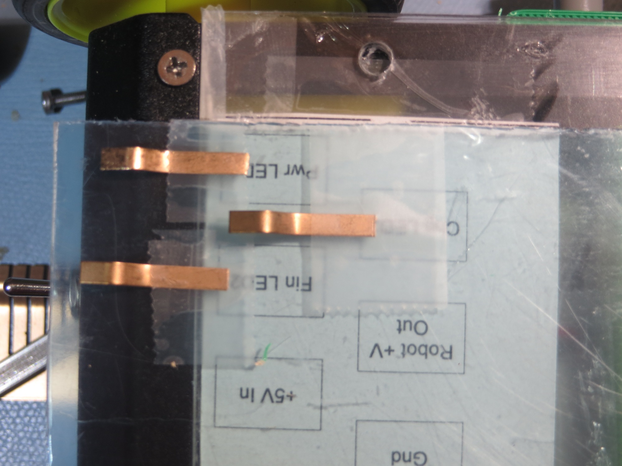
Contacts well before engaging

With the above arrangement, there is basically no possibility of a contact finger bridging the gap between two contacts, and even drastic mis-registration of the robot onto the platform will result in correct contact engagement.  That’s my story, and I’m sticking to it! ;-).

Here’s a short video clip of a few simulated engagement/disengagement cycles


The next step was to fabricate the robot-bottom contacts from copper tape and wire them to the charging module.  Here are some photos of the finished product.
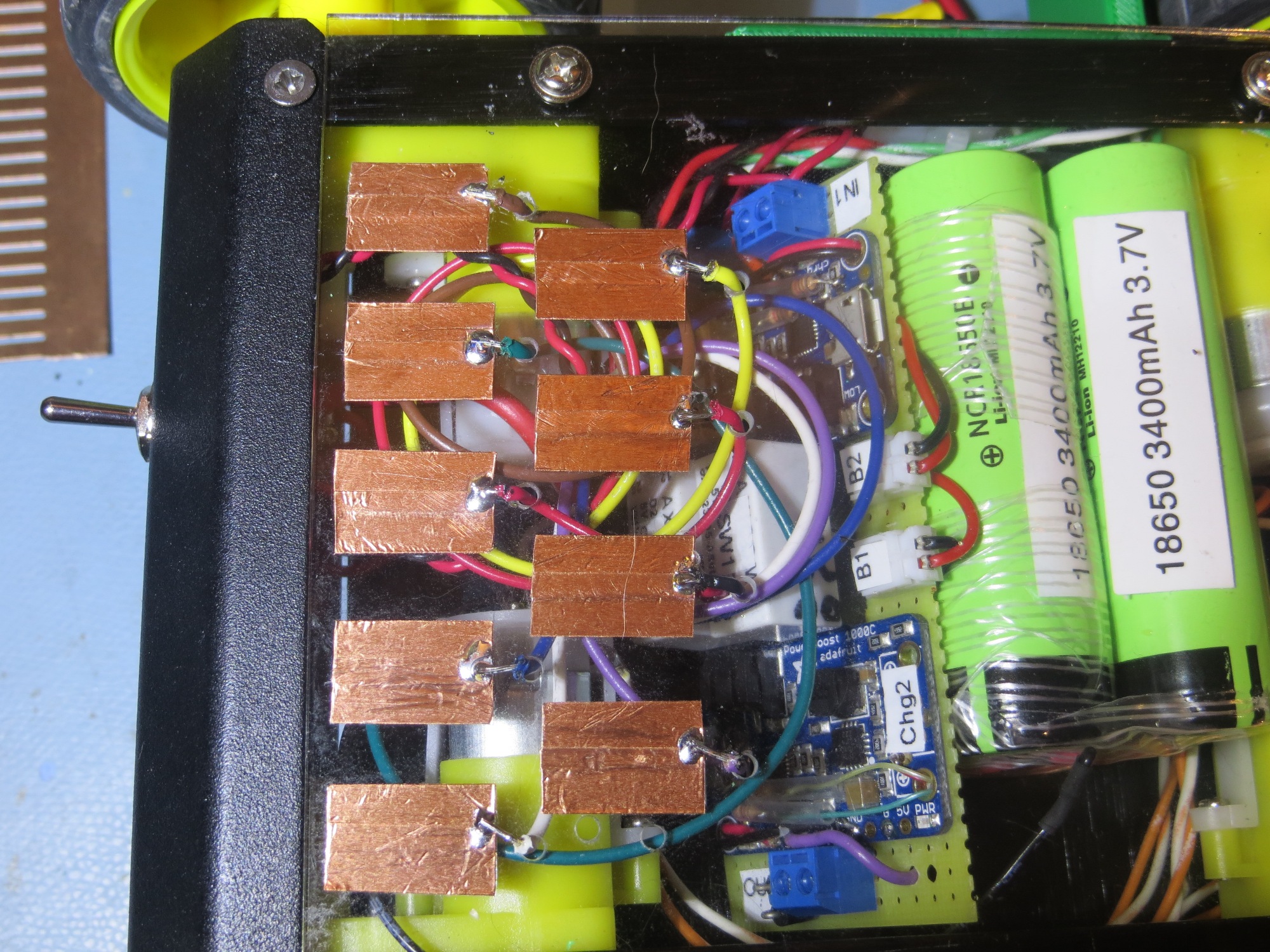
Interface contacts fabricated and wired to charging module

When I looked at the completed module, I recognized that I still had two issues remaining.  The first and more important one is that I needed a strip of insulation to having the sliding contacts short to ground  or each other as they moved across it on their way to their final destination. The second one was that it would be nice to label the contacts so that I wouldn’t have to trust my very untrustworthy memory.  As I thought about this, it occurred to me that I could kill two birds with one stone by placing a label strip on the chassis, as shown below – cool huh!
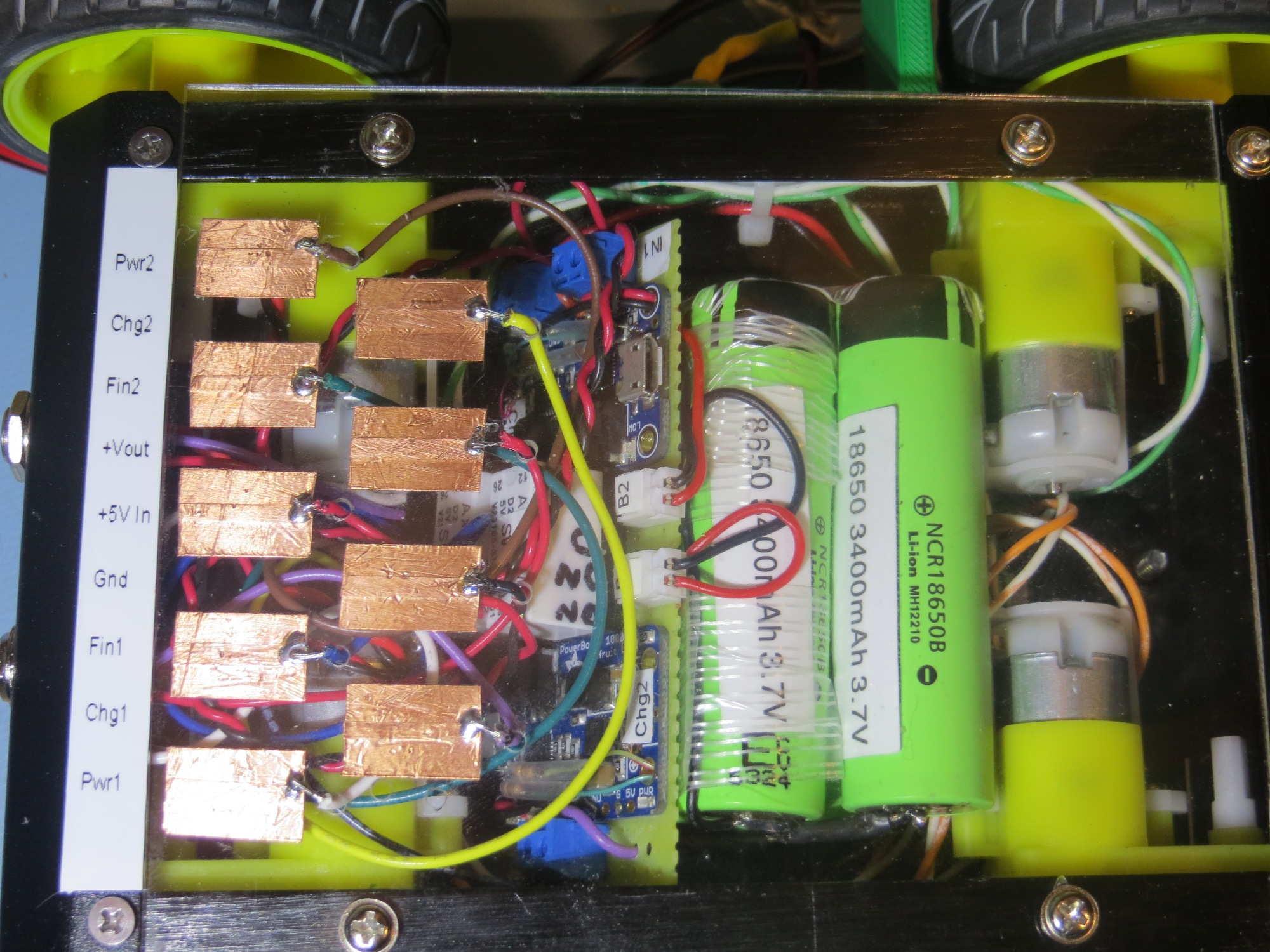
Added labelling to contact array. This was a ‘two-fer’ as it also prevents contact shorting to chassis

Frank