Posted 10 November 2024
Last month I tried ‘Klipperizing’ my Flashforge Creator Pro 2 (FFCP2) IDEX 3D printer, and it was an unmitigated disaster. After uploading the Klipper firmware, the printer refused to boot up, and I eventually I had to buy and install a new motherboard to regain functionality. Since then I have discovered that my original motherboard seems to be undamaged, but I can’t get it to boot into the FFCP2 firmware.
So, I have embarked on a quest to figure out how to restore FFCP2 functionality to my original STM32-based FFCP2 motherboard.
I started on this journey with one of the ‘blue pill’ devices I happened to have in my parts drawer. They are generally based on the STM32F1 series, so hopefully not different enough from the STM32F407 to matter.
To start with, I connected up my laptop to the ‘blue pill’ board using a ST-LINK clone and was able to program it via VS2022/VsMicro with the ST-LINK upload option selected, as shown in the following screenshot (note – this was done with the ‘blue pill’ jumpers set as shown in this photo):
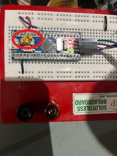
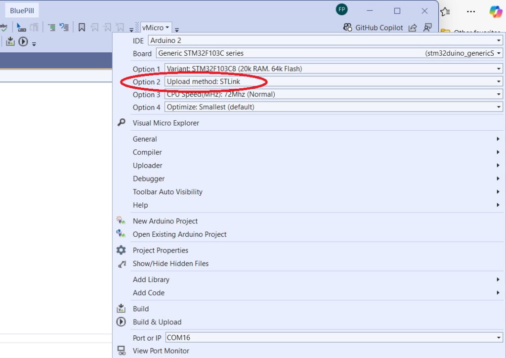
And here is part of the ‘verbose’ build output:
|
1 2 3 4 5 6 7 8 9 10 11 12 13 14 15 16 17 18 19 20 21 22 23 24 25 26 27 28 29 30 31 32 33 34 35 36 37 38 |
Program BluePill size: 12924 bytes (used 20% of a 65536 byte maximum) (2.27 secs) Minimum Memory Usage: 2064 bytes (10% of a 20480 byte maximum) # Copy build result to 'Project>Property Pages>Intermediate Directory' # Destination: "file:///C:/Users/Frank/Documents/Arduino/BluePill/BluePill/obj/ARM64/Release/" Uploading 'BluePill' to 'Generic STM32F103C series(stm32duino_genericSTM32F103C)' using 'COM16' Uploader started for board Generic STM32F103C series(stm32duino_genericSTM32F103C) Upload method will be: bootloader Uploading via Bootloader Resetting to bootloader via Serial Serial reset Reset via USB Serial completed c:\Users\Frank\AppData\Local\Arduino15\packages\stm32duino\tools\stm32tools\2022.9.26\win\stlink_upload.bat "C:\Users\Frank\AppData\Local\Temp\VMBuilds\BluePill\stm32duino_genericSTM32F103C\Release/BluePill.ino.bin" STM32 ST-LINK CLI v3.3.0.0 The upload process has finished. STM32 ST-LINK Command Line Interface ST-LINK SN: 0F0017000C2D363637365744 ST-LINK Firmware version: V2J37S7 (Need Update) Connected via SWD. SWD Frequency = 4000K. Target voltage = 3.2 V Connection mode: Normal Reset mode: Software reset Device ID: 0x410 Device flash Size: 128 Kbytes Device family: STM32F10xx Medium-density Loading file... Flash Programming: File : C:\Users\Frank\AppData\Local\Temp\VMBuilds\BluePill\stm32duino_genericSTM32F103C\Release\BluePill.ino.bin Address : 0x08000000 Memory programming... ±±±±±±±±±±±±±±±±±±±±±±±±±±±±±±±±±±±±±±±±±±±±±±±±±± 0% 0%ÛÛÛÛÛÛÛÛÛÛÛÛÛÛÛÛÛÛÛÛÛÛÛÛÛÛÛÛÛ 59%ÛÛÛÛÛÛÛÛÛÛÛÛÛÛÛÛÛÛÛÛÛ 100% Memory programmed in 0s and 610ms. Programming Complete. MCU Reset. Application started. |
I also tried some of the different upload modes advertised in the vMicro menu, as shown in the following conversation from the vMicro forum:
|
1 2 3 4 5 6 7 8 9 10 11 12 13 14 |
Thanks for the report, and that sounds like an interesting though difficult project. STLink + OpenOCD (vMicro) CPUTap Error seems to be due to the F1x expecting the IDCode "0x1ba01477" from the MCU, wheras the board is reporting "0x2ba01477" which is in the F2x configuration. We will look at why this configuration isn't working, however as the STLiNK option works, it is best to continue with that currently. STM32DuinoBootloader The error suggests you don't have the Java Runtime Environment (JRE) installed, or it as not been added to the PATH Environment Variable in Windows. Once installed correctly you should be able to open a command line and type "java --version", and it will display the version information for the JRE Installed. I believe this uses a modified Maple DFU Bootloader, which can be found in the STM32Duino documentation below: https://github.com/stm32duino/Arduino_Core_STM32/wiki/Upload-methods#maple-dfu-b... Serial This requires the bootloader to be flashed to the Bluepill which supports Serial Upload. Instructions are linked on the "Bootloader" tab on the below page: https://www.visualmicro.com/page/STMicroelectronics-STM32-Overview.aspx |
After receiving this input, I installed the JRE, confirmed it was actually there, and then tried the ‘STM32DuinoBootloader’ option again using the USB connector. It still failed, with the output shown below:
|
1 2 3 4 5 6 7 8 9 10 11 12 13 14 15 16 17 18 19 20 21 22 23 24 25 26 27 28 29 30 31 32 33 34 35 36 37 38 39 40 41 42 43 44 45 46 47 48 49 50 51 52 53 54 55 56 57 58 59 60 61 62 63 64 65 66 67 68 69 70 71 72 73 74 75 76 77 78 79 80 81 82 83 84 85 86 87 88 89 90 91 92 93 94 95 96 97 98 99 100 101 102 103 104 105 106 107 108 109 110 111 112 113 114 115 116 117 118 119 120 121 122 123 124 125 126 127 128 129 130 131 132 133 134 135 136 137 138 139 140 141 142 143 144 145 146 147 148 149 150 151 152 153 154 155 156 157 158 159 160 161 162 163 164 165 166 167 168 169 170 171 172 173 174 175 176 177 178 179 180 181 182 183 184 185 186 187 188 189 190 191 192 193 194 195 196 197 198 199 200 201 202 203 204 205 206 207 208 209 210 211 212 213 214 215 216 217 218 219 220 221 222 223 224 225 226 227 228 229 230 231 232 233 234 235 236 237 238 239 240 241 242 243 244 245 246 247 248 249 250 251 252 253 254 255 256 257 258 259 260 261 262 263 264 265 266 267 268 269 270 271 272 273 274 275 276 277 278 279 280 281 282 283 284 285 286 287 288 289 290 291 292 293 294 295 296 297 298 299 300 301 302 303 304 305 306 307 308 309 310 311 312 313 314 315 316 317 318 319 320 321 322 323 324 325 326 327 328 329 330 331 332 333 334 335 336 337 338 339 340 341 342 343 344 345 346 347 348 349 350 351 352 353 354 355 356 357 358 359 360 361 362 363 364 365 366 367 368 369 370 371 372 373 374 375 376 377 378 379 380 381 382 383 384 385 386 387 388 389 390 391 392 393 394 395 396 397 398 399 400 401 402 403 404 405 406 407 408 409 410 411 412 413 414 415 416 417 418 419 420 421 422 423 424 425 426 427 428 429 430 431 432 433 434 435 436 437 438 439 440 441 442 443 444 445 446 447 448 449 450 451 452 453 454 455 456 457 458 459 460 461 462 463 464 465 466 467 468 469 470 471 472 473 474 475 476 477 478 479 480 481 482 483 484 485 486 487 488 489 490 491 492 493 494 495 496 497 498 499 500 501 502 503 504 505 506 507 508 509 510 511 512 513 514 515 516 517 518 519 520 521 522 523 524 525 526 527 528 529 530 531 532 533 534 535 536 537 538 539 540 541 542 543 544 545 546 547 548 549 550 551 552 553 554 555 556 557 558 559 560 561 562 563 564 565 566 567 568 569 570 571 572 573 574 575 576 577 578 579 580 581 582 583 584 585 586 587 588 589 590 591 592 593 594 595 596 597 598 599 600 601 602 603 604 605 606 607 608 609 610 611 612 613 614 615 616 617 618 619 620 621 622 623 624 625 626 627 628 629 630 631 632 633 634 635 636 637 638 639 640 641 642 643 644 645 646 647 648 649 650 651 652 653 654 655 656 657 658 659 660 661 662 663 664 665 666 667 668 669 670 671 672 673 674 675 676 677 678 679 680 681 682 683 684 685 686 687 688 689 690 691 692 693 694 695 696 697 698 699 700 701 702 703 704 705 706 707 708 709 710 711 712 713 714 715 716 717 718 719 720 721 722 723 724 725 726 727 728 729 730 731 732 733 734 735 736 737 738 739 740 741 742 743 744 745 746 747 748 749 750 751 752 753 754 755 756 757 758 759 760 761 762 763 764 765 766 767 768 769 770 771 772 773 774 775 776 777 778 779 780 781 782 783 784 785 786 787 788 789 790 791 792 793 794 795 796 797 798 799 800 801 802 803 804 805 806 807 808 809 810 811 812 813 814 815 816 817 818 819 820 821 822 823 824 825 826 827 828 829 830 831 832 833 834 835 836 837 838 839 840 841 842 843 844 845 846 847 848 849 850 |
Board Properties name=Generic STM32F103C series vid.0=0x1EAF pid.0=0x0004 build.variant=generic_stm32f103c build.vect=VECT_TAB_ADDR=0x8002000 build.core=maple build.board=GENERIC_STM32F103C build.error_led_port=GPIOC build.error_led_pin=13 upload.use_1200bps_touch=false upload.file_type=bin upload.auto_reset=true upload.tool=maple_upload upload.protocol=maple_dfu menu.device_variant.STM32F103C8=STM32F103C8 (20k RAM. 64k Flash) menu.device_variant.STM32F103C8.build.cpu_flags=-DMCU_STM32F103C8 menu.device_variant.STM32F103C8.build.ldscript=ld/jtag_c8.ld menu.device_variant.STM32F103C8.upload.maximum_size=65536 menu.device_variant.STM32F103C8.upload.maximum_data_size=20480 menu.device_variant.STM32F103CB=STM32F103CB (20k RAM. 128k Flash) menu.device_variant.STM32F103CB.build.cpu_flags=-DMCU_STM32F103CB menu.device_variant.STM32F103CB.build.ldscript=ld/jtag.ld menu.device_variant.STM32F103CB.upload.maximum_size=131072 menu.device_variant.STM32F103CB.upload.maximum_data_size=20480 menu.upload_method.DFUUploadMethod=STM32duino bootloader menu.upload_method.DFUUploadMethod.upload.protocol=maple_dfu menu.upload_method.DFUUploadMethod.upload.tool=maple_upload menu.upload_method.DFUUploadMethod.build.upload_flags=-DSERIAL_USB -DGENERIC_BOOTLOADER menu.upload_method.DFUUploadMethod.build.vect=VECT_TAB_ADDR=0x8002000 menu.upload_method.DFUUploadMethod.build.ldscript=ld/bootloader_20.ld menu.upload_method.DFUUploadMethod.upload.usbID=1EAF:0003 menu.upload_method.DFUUploadMethod.upload.altID=2 menu.upload_method.serialMethod=Serial menu.upload_method.serialMethod.upload.protocol=maple_serial menu.upload_method.serialMethod.upload.tool=serial_upload menu.upload_method.serialMethod.build.upload_flags=-DCONFIG_MAPLE_MINI_NO_DISABLE_DEBUG menu.upload_method.STLinkMethod=STLink menu.upload_method.STLinkMethod.upload.protocol=STLink menu.upload_method.STLinkMethod.upload.tool=stlink_upload menu.upload_method.STLinkMethod.build.upload_flags=-DCONFIG_MAPLE_MINI_NO_DISABLE_DEBUG=1 -DSERIAL_USB -DGENERIC_BOOTLOADER menu.upload_method.BMPMethod=BMP (Black Magic Probe) menu.upload_method.BMPMethod.upload.protocol=gdb_bmp menu.upload_method.BMPMethod.upload.tool=bmp_upload menu.upload_method.BMPMethod.build.upload_flags=-DCONFIG_MAPLE_MINI_NO_DISABLE_DEBUG menu.upload_method.jlinkMethod=JLink menu.upload_method.jlinkMethod.upload.protocol=jlink menu.upload_method.jlinkMethod.upload.tool=jlink_upload menu.upload_method.jlinkMethod.build.upload_flags=-DCONFIG_MAPLE_MINI_NO_DISABLE_DEBUG=1 -DSERIAL_USB -DGENERIC_BOOTLOADER menu.upload_method.HIDUploadMethod=HID bootloader 2.0 menu.upload_method.HIDUploadMethod.upload.tool=hid_upload menu.upload_method.HIDUploadMethod.build.upload_flags=-DSERIAL_USB -DGENERIC_BOOTLOADER menu.upload_method.HIDUploadMethod.build.vect=VECT_TAB_ADDR=0x8001000 menu.upload_method.HIDUploadMethod.build.ldscript=ld/hid_bootloader.ld menu.cpu_speed.speed_72mhz=72Mhz (Normal) menu.cpu_speed.speed_72mhz.build.f_cpu=72000000L menu.cpu_speed.speed_48mhz=48Mhz (Slow - with USB) menu.cpu_speed.speed_48mhz.build.f_cpu=48000000L menu.cpu_speed.speed_128mhz=Overclocked 128Mhz NO USB SERIAL. MANUAL RESET NEEDED TO UPLOAD menu.cpu_speed.speed_128mhz.build.f_cpu=128000000L menu.opt.osstd=Smallest (default) menu.opt.o1std=Fast (-O1) menu.opt.o1std.build.flags.optimize=-O1 menu.opt.o1std.build.flags.ldspecs= menu.opt.o2std=Faster (-O2) menu.opt.o2std.build.flags.optimize=-O2 menu.opt.o2std.build.flags.ldspecs= menu.opt.o3std=Fastest (-O3) menu.opt.o3std.build.flags.optimize=-O3 menu.opt.o3std.build.flags.ldspecs= menu.opt.ogstd=Debug (-g) menu.opt.ogstd.build.flags.optimize=-Og menu.opt.ogstd.build.flags.ldspecs= vm.debug.class_type=VM_DBT_USBSERIAL vm.debug.main_port_name=Serial tools.openocd.debug.build.openocdscript=target/stm32f1x.cfg menu.upload_method.f2232h=F2232H Dual RS232 + OpenOCD (vMicro) menu.upload_method.f2232h.upload.tool=ftdiocd menu.upload_method.f2232h.upload.openocddebugger=ftdi/minimodule-lowcost.cfg menu.upload_method.cjmcuf2232h=F2232H Single RS232 + OpenOCD (vMicro) menu.upload_method.cjmcuf2232h.upload.tool=ftdiocd menu.upload_method.cjmcuf2232h.upload.openocddebugger=ftdi/um232h.cfg menu.upload_method.ft2232mm=JLink + OpenOCD (vMicro) menu.upload_method.ft2232mm.upload.tool=jlinkocd menu.upload_method.ft2232mm.upload.openocddebugger=jlink.cfg menu.upload_method.stlinkv2=STLink v2 + OpenOCD (vMicro) menu.upload_method.stlinkv2.upload.tool=openocd menu.upload_method.stlinkv2.upload.openocddebugger=stlink.cfg menu.upload_method.stlinkv21=STLink v2.1 + OpenOCD (vMicro) menu.upload_method.stlinkv21.upload.tool=openocd menu.upload_method.stlinkv21.upload.openocddebugger=stlink.cfg menu.upload_method.bmp=Black Magic + GDB (vMicro) menu.upload_method.bmp.upload.tool=vmbmp menu.upload_method.bmp.upload.openocddebugger= menu.upload_method.daplink=DAPLink + OpenOCD (vMicro) menu.upload_method.daplink.upload.tool=daplink runtime.ide.path=c:\program files\microsoft visual studio\2022\community\common7\ide\extensions\jbmj4m1q.esc\Micro Platforms\visualmicro\ide runtime.os=windows build.system.path=c:\Users\Frank\AppData\Local\Arduino15\packages\stm32duino\hardware\STM32F1\2022.9.26\system runtime.ide.version=108010 target_package=stm32duino target_platform=STM32F1 runtime.hardware.path=c:\Users\Frank\AppData\Local\Arduino15\packages\stm32duino\hardware\STM32F1 originalid=genericSTM32F103C _id=genericSTM32F103C intellisense.tools.path={runtime.tools.arm-none-eabi-gcc.path} intellisense.include.paths={runtime.tools.CMSIS.path}/CMSIS/Core/Include/;{intellisense.tools.path}\arm-none-eabi;{intellisense.tools.path}\arm-none-eabi\include;{intellisense.tools.path}\arm-none-eabi\include\c++\9.2.1\arm-none-eabi;{intellisense.tools.path}\arm-none-eabi\include\c++\9.2.1;{intellisense.tools.path}\arm-none-eabi\include\c++\9.2.1\tr1;{intellisense.tools.path}\arm-none-eabi\include\sys;{intellisense.tools.path}\arm-none-eabi\include\c++\9.2.1\arm-none-eabi\bits; {intellisense.tools.path}\lib\gcc\arm-none-eabi\9.2.1\include;{intellisense.tools.path}\arm-none-eabi\include\c++\4.8.3\arm-none-eabi;{intellisense.tools.path}\arm-none-eabi\include\c++\4.8.3;{intellisense.tools.path}\arm-none-eabi\include\c++\4.8.3\tr1;{intellisense.tools.path}\arm-none-eabi\include\c++\4.8.3\arm-none-eabi\bits;{intellisense.tools.path}\lib\gcc\arm-none-eabi\4.8.3\include;{vm.intellisense.add-paths} upload.8dot3=false tools.gdb.pre_init.tool=openocd tools.gdb.cmd=arm-none-eabi-gdb.exe tools.gdb.path={runtime.tools.arm-none-eabi-gcc.path}/bin tools.gdb.pattern="{path}/{cmd}" -interpreter=mi -d "{build.project_path}" tools.gdb.openocd.cmd=bin/openocd.exe tools.gdb.openocd.path={runtime.vm.ide.tools.openocd.path} tools.gdb.openocd.params.verbose=-d2 tools.gdb.openocd.params.quiet=-d0 tools.gdb.openocd.pattern="{path}/{cmd}" -l "{{build.path}/{build.project_name}_DebugOpenOCD.log}" -s "{path}/scripts/" -f "{path}/scripts/{build.openocdscript}" tools.openocd.debug.path={runtime.tools.openocd-0.10.0.20200213.path} tools.openocd.debug.cmd=bin/openocd.exe tools.openocd.debug.cmd.windows=bin/openocd.exe tools.openocd.debug.params.verbose=-d2 tools.openocd.debug.params.quiet=-d0 tools.openocd.initCmd=-c "init; reset halt" vs-cmd.Debug.AttachtoProcess.tools.openocd.initCmd=-c "init" tools.openocd.debug.args={params.verbose} -l "{{build.path}/{build.project_name}_DebugOpenOCD.log}" -s"{path}/scripts/" -f "{path}/scripts/interface/{build.openocddebugger}" -f "{path}/scripts/{build.openocdscript}" {initCmd} tools.openocd.debug.address=localhost:3333 tools.bmp_upload.debug.args=-nh -b 115200 -ex "target extended-remote \.\{serial.debug.port}" -ex "monitor swdp_scan" -ex "attach 1" tools.f2232h.vmserver.targetCmd=-c "transport select swd" -c "ftdi_layout_signal SWD_EN -data 0" -f "{tools.openocd.debug.build.openocdscript}" tools.cjmcuf2232h.vmserver.targetCmd=-c "transport select swd" -c "ftdi_layout_signal SWD_EN -data 0" -f "{tools.openocd.debug.build.openocdscript}" tools.f2232mm.vmserver.targetCmd=-c "transport select swd" -c "ftdi_layout_signal SWD_EN -data 0" -f "{tools.openocd.debug.build.openocdscript}" tools.jlink.vmserver.targetCmd=-c "transport select swd" -f "{tools.openocd.debug.build.openocdscript}" tools.stlinkv2.vmserver.targetCmd=-f "{tools.openocd.debug.build.openocdscript}" tools.stlinkv2.debug.args=-ex "flushregs" -ex "continue" tools.daplink.vmserver.targetCmd=-c "transport select swd" -f "{tools.openocd.debug.build.openocdscript}" debug_menu.hwdebugger.bmp=Black Magic (External) debug_menu.hwdebugger.bmp.debug.tool=bmp_upload meta_bmp.sentence=This debugger requires the 20-pin ribbon cable to link to your target, see connections below meta_bmp.comment=Ensure the COM Port for the Black Magic is selected before attaching the Debugger. Set vMicro > Debugger > 'Compiler Optimization' to 'No Project', 'No Project + Libraries' or 'None' when debugging. (NOTE: Changing the optimization setting for this platform might cause compilation errors with certain code such as HardwareSerial.) meta_bmp.image.connect=https://www.visualmicro.com/pics/Debug-Help-STM32-BMP-Connections.png meta_bmp.image.operation=https://www.visualmicro.com/pics/Debug-Break-STM32-BMP-VSOnly.png meta_bmp.reference.usage.url=https://www.visualmicro.com/page/STM32-Debugging.aspx debug_menu.hwdebugger.f2232h=F2232H Dual RS232 debug_menu.hwdebugger.f2232h.debug.tool=f2232h meta_f2232h.sentence=This debugger will require some wiring to connect it to your target STM32 board meta_f2232h.comment=Wiring can be found in the below image, and the 'https://zadig.akeo.ie/' tool is required to replace the USB Driver on Interface 0 with 'WinUSB'. Set vMicro > Debugger > 'Compiler Optimization' to 'No Project', 'No Project + Libraries' or 'None' when debugging. (NOTE: Changing the optimization setting for this platform might cause compilation errors with certain code such as HardwareSerial.) meta_f2232h.image.connect=https://www.visualmicro.com/pics/Debug-Break-STM32-FT2232H-Connections.png meta_f2232h.reference.usage.url=https://www.visualmicro.com/page/STM32-Debugging.aspx debug_menu.hwdebugger.cjmcuf2232h=F2232H Single RS232 debug_menu.hwdebugger.cjmcuf2232h.debug.tool=cjmcuf2232h meta_cjmcuf2232h.sentence=This debugger will require some wiring to connect it to your target STM32 board meta_cjmcuf2232h.comment=Wiring can be found in the below image, and the 'https://zadig.akeo.ie/' tool is required to replace the USB Driver on Interface 0 with 'WinUSB'. Set vMicro > Debugger > 'Compiler Optimization' to 'No Project', 'No Project + Libraries' or 'None' when debugging. (NOTE: Changing the optimization setting for this platform might cause compilation errors with certain code such as HardwareSerial.) meta_cjmcuf2232h.image.connect=https://www.visualmicro.com/pics/Debug-Break-STM32-CJMCU2232H-Connections.png meta_cjmcuf2232h.reference.usage.url=https://www.visualmicro.com/page/STM32-Debugging.aspx debug_menu.hwdebugger.f2232mm=F2232 MiniModule debug_menu.hwdebugger.f2232mm.debug.tool=f2232mm meta_f2232mm.sentence=This debugger will require some wiring to allow it to function, and connect to your target STM32 board meta_f2232mm.comment=Wiring can be found in the below image, and the 'https://zadig.akeo.ie/' tool is required to replace the USB Driver on Interface 0 with 'WinUSB'. Set vMicro > Debugger > 'Compiler Optimization' to 'No Project', 'No Project + Libraries' or 'None' when debugging. (NOTE: Changing the optimization setting for this platform might cause compilation errors with certain code such as HardwareSerial.) meta_f2232mm.image.connect=https://www.visualmicro.com/pics/Debug-Help-STM32-FT2232MM-Connections.png meta_f2232mm.image.operation=https://www.visualmicro.com/pics/Debug-Help-STM32-FT2232MM-VSOnly.png meta_f2232mm.reference.usage.url=https://www.visualmicro.com/page/STM32-Debugging.aspx debug_menu.hwdebugger.jlink=Segger J-Link debug_menu.hwdebugger.jlink.debug.tool=jlink meta_jlink.sentence=This debugger will require some wiring to connect it to your target STM32 board meta_jlink.comment=Wiring can be found in the below image, and the 'https://zadig.akeo.ie/' tool is required to replace the USB Driver on Interface 0 with 'WinUSB'. Set vMicro > Debugger > 'Compiler Optimization' to 'No Project', 'No Project + Libraries' or 'None' when debugging. (NOTE: Changing the optimization setting for this platform might cause compilation errors with certain code such as HardwareSerial.) meta_jlink.image.connect=https://www.visualmicro.com/pics/Debug-Help-STM32-Jlink-Connections.png meta_jlink.image.operation=https://www.visualmicro.com/pics/Debug-Help-STM32-STM32-Jlink-VSOnly.png meta_jlink.reference.usage.url=https://www.visualmicro.com/page/STM32-Debugging.aspx debug_menu.hwdebugger.stlinkv21=STLink v2.1 (Onboard) debug_menu.hwdebugger.stlinkv21.debug.tool=stlinkv2 meta_stlinkv21.sentence=This debugger is built onto the board, and requires both jumpers to be present on the STLINK/Board header meta_stlinkv21.comment=Wiring can be found in the below image, and the 'https://zadig.akeo.ie/' tool is required to replace the USB Driver on Interface 0 with 'WinUSB'. Set vMicro > Debugger > 'Compiler Optimization' to 'No Project', 'No Project + Libraries' or 'None' when debugging. (NOTE: Changing the optimization setting for this platform might cause compilation errors with certain code such as HardwareSerial.) meta_stlinkv21.image.connect=https://www.visualmicro.com/pics/Debug-Help-STM32-STlinkBuiltIn-Connections.png meta_stlinkv21.image.operation=https://www.visualmicro.com/pics/Debug-Break-STM32-STlinkBuiltIn-VSOnly.png meta_stlinkv21.reference.usage.url=https://www.visualmicro.com/page/STM32-Debugging.aspx debug_menu.hwdebugger.stlinkv2=STLink v2 (External) debug_menu.hwdebugger.stlinkv2.debug.tool=stlinkv2 meta_stlinkv2.sentence=This debugger requires the 20-pin ribbon cable to link to your target. meta_stlinkv2.comment=Further info can be found in the below image, and the 'https://zadig.akeo.ie/' tool is required to replace the USB Driver on Interface 0 with 'WinUSB'. Set vMicro > Debugger > 'Compiler Optimization' to 'No Project', 'No Project + Libraries' or 'None' when debugging. (NOTE: Changing the optimization setting for this platform might cause compilation errors with certain code such as HardwareSerial.) meta_stlinkv2.image.connect=https://www.visualmicro.com/pics/Debug-Help-STM32-STlink-Connections.png meta_stlinkv2.image.operation=https://www.visualmicro.com/pics/Debug-Break-STM32-STlink-VSOnly.png meta_stlinkv2.reference.usage.url=https://www.visualmicro.com/page/STM32-Debugging.aspx debug_menu.hwdebugger.daplink=DAPLink debug_menu.hwdebugger.daplink.debug.tool=daplink meta_daplink.sentence=This debugger additional wiring to link to your target, see links below meta_daplink.comment=Optionally set vMicro > Debugger > 'Compiler Optimization' to 'No Project', 'No Project + Libraries' or 'None' when debugging. (NOTE: Changing the optimization setting for this platform might cause compilation errors with certain code such as HardwareSerial.) meta_daplink.image.connect=https://www.visualmicro.com/pics/Debug-Help-STM32-DAPLink-Connections.png meta_daplink.image.operation=https://www.visualmicro.com/pics/Debug-Break-STM32-DAPLink-VSOnly.png meta_daplink.reference.usage.url=https://www.visualmicro.com/page/STM32-Debugging.aspx tools.openocd.upload.elf.message=****[vMicro]**** Uploading ELF : tools.openocd.upload.path={runtime.tools.openocd-0.10.0.20200213.path} tools.openocd.upload.cmd=bin/openocd.exe tools.openocd.upload.cmd.windows=bin/openocd.exe tools.openocd.upload.params.verbose=-d2 tools.openocd.upload.params.quiet=-d0 tools.openocd.upload.pattern="{upload.path}/{upload.cmd}" {upload.verbose} -s "{upload.path}/scripts/" -f "interface/{upload.openocddebugger}" -f "{upload.openocdscript}" -c "echo -n {{upload.elf.message}}" -c "reset_config; telnet_port disabled; program {{build.path}/{build.project_name}.elf} reset;reset_config;shutdown" tools.openocd.upload.extra_params= tools.openocd.upload.protocol= tools.openocd.protocol= tools.openocd.upload.openocdscript=target/stm32f1x.cfg tools.jlinkocd.upload.elf.message=****[vMicro]**** Uploading ELF : tools.jlinkocd.upload.path={runtime.tools.openocd-0.10.0.20200213.path} tools.jlinkocd.upload.cmd=bin/openocd.exe tools.jlinkocd.upload.cmd.windows=bin/openocd.exe tools.jlinkocd.upload.params.verbose=-d2 tools.jlinkocd.upload.params.quiet=-d0 tools.jlinkocd.upload.pattern="{upload.path}/{upload.cmd}" {upload.verbose} -s "{upload.path}/scripts/" -f "interface/{upload.openocddebugger}" -c "transport select swd" -f "{upload.openocdscript}" -c "echo -n {{upload.elf.message}}" -c "reset_config; telnet_port disabled; program {{build.path}/{build.project_name}.elf} reset;reset_config;shutdown" tools.jlinkocd.upload.extra_params= tools.jlinkocd.upload.protocol= tools.jlinkocd.protocol= tools.jlinkocd.upload.openocdscript=target/stm32f1x.cfg tools.ftdiocd.upload.elf.message=****[vMicro]**** Uploading ELF : tools.ftdiocd.upload.path={runtime.tools.openocd-0.10.0.20200213.path} tools.ftdiocd.upload.cmd=bin/openocd.exe tools.ftdiocd.upload.cmd.windows=bin/openocd.exe tools.ftdiocd.upload.params.verbose=-d2 tools.ftdiocd.upload.params.quiet=-d0 tools.ftdiocd.upload.pattern="{upload.path}/{upload.cmd}" {upload.verbose} -s "{upload.path}/scripts/" -f "interface/{upload.openocddebugger}" -c "transport select swd" -c "ftdi_layout_signal SWD_EN -data 0" -f "{upload.openocdscript}" -c "echo -n {{upload.elf.message}}" -c "reset_config; telnet_port disabled; program {{build.path}/{build.project_name}.elf} reset;reset_config;shutdown" tools.ftdiocd.upload.extra_params= tools.ftdiocd.upload.protocol= tools.ftdiocd.protocol= tools.ftdiocd.upload.openocdscript=target/stm32f1x.cfg tools.vmbmp.upload.cmd=bin/arm-none-eabi-gdb.exe tools.vmbmp.upload.cmd.windows=bin/arm-none-eabi-gdb.exe tools.vmbmp.upload.path={runtime.tools.arm-none-eabi-gcc.path} tools.vmbmp.upload.pattern={upload.path}/{upload.cmd} -nx -b 230400 -batch -ex "set confirm off" -ex "target extended-remote \.\{serial.port}" -ex "monitor swdp_scan" -ex "attach 1" -ex "load" -ex "compare-sections" -ex "kill" "{build.path}/{build.project_name}.elf" -ex "kill" tools.daplink.upload.programCmd=-c "reset_config; telnet_port disabled; program {{build.path}/{build.project_name}.elf} reset;reset_config;shutdown" tools.daplink.upload.targetCmd=-c "transport select swd" -f "{tools.openocd.upload.openocdscript}" version=0.1.2 compiler.warning_flags=-w -DDEBUG_LEVEL=DEBUG_NONE compiler.warning_flags.none=-w -DDEBUG_LEVEL=DEBUG_NONE compiler.warning_flags.default=-DDEBUG_LEVEL=DEBUG_NONE compiler.warning_flags.more=-Wall -DDEBUG_LEVEL=DEBUG_FAULT compiler.warning_flags.all=-Wall -Wextra -DDEBUG_LEVEL=DEBUG_ALL compiler.path={runtime.tools.arm-none-eabi-gcc.path}/bin/ compiler.c.cmd=arm-none-eabi-gcc compiler.c.flags=-c -g {build.flags.optimize} {compiler.warning_flags} -std=gnu11 -MMD -ffunction-sections -fdata-sections -nostdlib --param max-inline-insns-single=500 -DBOARD_{build.variant} -D{build.vect} -DERROR_LED_PORT={build.error_led_port} -DERROR_LED_PIN={build.error_led_pin} compiler.c.elf.cmd=arm-none-eabi-g++ compiler.c.elf.flags={build.flags.optimize} -Wl,--gc-sections {build.flags.ldspecs} compiler.S.cmd=arm-none-eabi-gcc compiler.S.flags=-c -g -x assembler-with-cpp -MMD compiler.cpp.cmd=arm-none-eabi-g++ compiler.cpp.flags=-c -g {build.flags.optimize} {compiler.warning_flags} -std=gnu++11 -MMD -ffunction-sections -fdata-sections -nostdlib --param max-inline-insns-single=500 -fno-rtti -fno-exceptions -fno-use-cxa-atexit -DBOARD_{build.variant} -D{build.vect} -DERROR_LED_PORT={build.error_led_port} -DERROR_LED_PIN={build.error_led_pin} compiler.ar.cmd=arm-none-eabi-ar compiler.ar.flags=rcs compiler.objcopy.cmd=arm-none-eabi-objcopy compiler.objcopy.eep.flags=-O ihex -j .eeprom --set-section-flags=.eeprom=alloc,load --no-change-warnings --change-section-lma .eeprom=0 compiler.elf2hex.flags=-O binary compiler.elf2hex.cmd=arm-none-eabi-objcopy compiler.ldflags={build.flags.ldspecs} compiler.size.cmd=arm-none-eabi-size compiler.define=-DARDUINO= build.f_cpu=72000000L build.mcu=cortex-m3 build.common_flags=-mthumb -march=armv7-m -D__STM32F1__ build.variant_system_lib=libmaple.a build.cpu_flags=-DMCU_STM32F103C8 build.hs_flag= build.upload_flags=-DSERIAL_USB -DGENERIC_BOOTLOADER build.flags.optimize=-Os build.flags.ldspecs=--specs=nano.specs build.extra_flags={build.upload_flags} {build.cpu_flags} {build.hs_flag} {build.common_flags} compiler.c.extra_flags= compiler.c.elf.extra_flags="-L{build.variant.path}/ld" compiler.cpp.extra_flags= compiler.S.extra_flags= compiler.ar.extra_flags= compiler.elf2hex.extra_flags= compiler.libs.c.flags="-I{build.system.path}/libmaple" "-I{build.system.path}/libmaple/include" "-I{build.system.path}/libmaple/stm32f1/include" "-I{build.system.path}/libmaple/usb/stm32f1" "-I{build.system.path}/libmaple/usb/usb_lib" recipe.c.o.pattern="{compiler.path}{compiler.c.cmd}" {compiler.c.flags} -mcpu={build.mcu} -DF_CPU={build.f_cpu} -DARDUINO={runtime.ide.version} -DARDUINO_{build.board} -DARDUINO_ARCH_{build.arch} {compiler.c.extra_flags} {build.extra_flags} {compiler.libs.c.flags} {includes} "{source_file}" -o "{object_file}" recipe.cpp.o.pattern="{compiler.path}{compiler.cpp.cmd}" {compiler.cpp.flags} -mcpu={build.mcu} -DF_CPU={build.f_cpu} -DARDUINO={runtime.ide.version} -DARDUINO_{build.board} -DARDUINO_ARCH_{build.arch} {compiler.cpp.extra_flags} {build.extra_flags} {build.cpu_flags} {build.hs_flag} {build.common_flags} {compiler.libs.c.flags} {includes} "{source_file}" -o "{object_file}" recipe.S.o.pattern="{compiler.path}{compiler.c.cmd}" {compiler.S.flags} -mcpu={build.mcu} -DF_CPU={build.f_cpu} -DARDUINO={runtime.ide.version} -DARDUINO_{build.board} -DARDUINO_ARCH_{build.arch} {compiler.S.extra_flags} {build.extra_flags} {build.cpu_flags} {build.hs_flag} {build.common_flags} {compiler.libs.c.flags} {includes} "{source_file}" -o "{object_file}" recipe.ar.pattern="{compiler.path}{compiler.ar.cmd}" {compiler.ar.flags} {compiler.ar.extra_flags} "{archive_file_path}" "{object_file}" recipe.c.combine.pattern="{compiler.path}{compiler.c.elf.cmd}" {compiler.c.elf.flags} -mcpu={build.mcu} "-T{build.variant.path}/{build.ldscript}" "-Wl,-Map,{build.path}/{build.project_name}.map" {compiler.c.elf.extra_flags} -o "{build.path}/{build.project_name}.elf" "-L{build.path}" -lm -lgcc -mthumb -Wl,--cref -Wl,--check-sections -Wl,--gc-sections -Wl,--unresolved-symbols=report-all -Wl,--warn-common -Wl,--warn-section-align -Wl,--warn-unresolved-symbols -Wl,--start-group {object_files} "{archive_file_path}" -Wl,--end-group recipe.objcopy.eep.pattern= recipe.objcopy.hex.pattern="{compiler.path}{compiler.elf2hex.cmd}" {compiler.elf2hex.flags} {compiler.elf2hex.extra_flags} "{build.path}/{build.project_name}.elf" "{build.path}/{build.project_name}.bin" recipe.size.pattern="{compiler.path}{compiler.size.cmd}" -A "{build.path}/{build.project_name}.elf" recipe.size.regex=^(?:\.text|\.data|\.rodata|\.text.align|\.ARM.exidx)\s+([0-9]+).* recipe.size.regex.data=^(?:\.data|\.bss|\.noinit)\s+([0-9]+).* recipe.output.tmp_file={build.project_name}.bin recipe.output.save_file={build.project_name}.{build.variant}.bin tools.maple_upload.cmd=maple_upload.bat tools.maple_upload.cmd.windows=maple_upload.bat tools.maple_upload.path={runtime.tools.stm32tools.path}/win tools.maple_upload.path.macosx={runtime.tools.stm32tools.path}/macosx tools.maple_upload.path.linux={runtime.tools.stm32tools.path}/linux tools.maple_upload.path.linux64={runtime.tools.stm32tools.path}/linux tools.maple_upload.upload.params.verbose=-d tools.maple_upload.upload.params.quiet= tools.maple_upload.upload.pattern="{path}/{cmd}" {serial.port.file} {upload.altID} {upload.usbID} "{build.path}/{build.project_name}.bin" "{runtime.ide.path}" tools.serial_upload.cmd=serial_upload.bat tools.serial_upload.cmd.windows=serial_upload.bat tools.serial_upload.cmd.macosx=serial_upload tools.serial_upload.path={runtime.tools.stm32tools.path}/win tools.serial_upload.path.macosx={runtime.tools.stm32tools.path}/macosx tools.serial_upload.path.linux={runtime.tools.stm32tools.path}/linux tools.serial_upload.path.linux64={runtime.tools.stm32tools.path}/linux tools.serial_upload.upload.params.verbose=-d tools.serial_upload.upload.params.quiet=n tools.serial_upload.upload.pattern="{path}/{cmd}" {serial.port.file} {upload.altID} {upload.usbID} "{build.path}/{build.project_name}.bin" tools.stlink_upload.cmd=stlink_upload.bat tools.stlink_upload.cmd.windows=stlink_upload.bat tools.stlink_upload.path.windows={runtime.tools.stm32tools.path}/win tools.stlink_upload.path.macosx={runtime.tools.stm32tools.path}/macosx tools.stlink_upload.path.linux={runtime.tools.stm32tools.path}/linux tools.stlink_upload.path.linux64={runtime.tools.stm32tools.path}/linux tools.stlink_upload.upload.params.verbose=-d tools.stlink_upload.upload.params.quiet= tools.stlink_upload.upload.pattern="{path}/{cmd}" "{build.path}/{build.project_name}.bin" tools.bmp_upload.cmd=arm-none-eabi-gdb tools.bmp_upload.path={runtime.tools.arm-none-eabi-gcc.path}/bin/ tools.bmp_upload.upload.speed=230400 tools.bmp_upload.upload.params.verbose= tools.bmp_upload.upload.params.quiet=-q --batch-silent tools.bmp_upload.upload.pattern="{path}{cmd}" -cd "{build.path}" -b {upload.speed} {upload.verbose} -ex "set debug remote 0" -ex "set target-async off" -ex "set remotetimeout 60" -ex "set mem inaccessible-by-default off" -ex "set confirm off" -ex "set height 0" -ex "target extended-remote {serial.port}" -ex "monitor swdp_scan" -ex "attach 1" -ex "x/wx 0x8000004" -ex "monitor erase_mass" -ex "echo 0x8000004 expect 0xffffffff after erase\n" -ex "x/wx 0x8000004" -ex "file {build.project_name}.elf" -ex "load" -ex "x/wx 0x08000004" -ex "tbreak main" -ex "run" -ex "echo \n\n\nUpload finished!" -ex "quit" tools.jlink_upload.cmd=jlink_upload.bat tools.jlink_upload.cmd.windows=jlink_upload.bat tools.jlink_upload.cmd.macosx=jlink_upload tools.jlink_upload.path={runtime.tools.stm32tools.path}/win tools.jlink_upload.path.macosx={runtime.tools.stm32tools.path}/macosx tools.jlink_upload.path.linux={runtime.tools.stm32tools.path}/linux tools.jlink_upload.path.linux64={runtime.tools.stm32tools.path}/linux tools.jlink_upload.upload.params.verbose=-d tools.jlink_upload.upload.params.quiet=n tools.jlink_upload.upload.pattern="{path}/{cmd}" "{build.path}/{build.project_name}.bin" tools.hid_upload.cmd=hid-flash.exe tools.hid_upload.cmd.windows=hid-flash.exe tools.hid_upload.cmd.macosx=hid_flash tools.hid_upload.path={runtime.tools.stm32tools.path}/win tools.hid_upload.path.macosx={runtime.tools.stm32tools.path}/macosx tools.hid_upload.path.linux={runtime.tools.stm32tools.path}/linux tools.hid_upload.path.linux64={runtime.tools.stm32tools.path}/linux tools.hid_upload.upload.params.verbose=-d tools.hid_upload.upload.params.quiet=n tools.hid_upload.upload.pattern="{path}/{cmd}" "{build.path}/{build.project_name}.bin" {serial.port.file} tools.stlink_upload.path={runtime.tools.stm32tools.path}/win vm_original_platform_name=STM32F1 Boards (Arduino_STM32) vm.platform.root.path=c:\program files\microsoft visual studio\2022\community\common7\ide\extensions\jbmj4m1q.esc\Micro Platforms\arduino16x upload.verify= tools.vmopenocd.cmd=bin/openocd.exe tools.vmopenocd.cmd.windows=bin/openocd.exe tools.vmopenocd.debug.params.verbose=-d2 tools.vmopenocd.debug.params.quiet=-d0 tools.vmopenocd.debug.address=localhost:3333 tools.vmopenocd.path={runtime.tools.openocd-0.10.0.20200213.path} tools.vmopenocd.scriptPath=-s "{path}/scripts/" tools.vmopenocd.logging=-l "{{build.path}/{build.project_name}_DebugOpenOCD.log}" tools.vmopenocd.boardCmd= tools.vmopenocd.targetCmd= tools.vmopenocd.initCmd= tools.vmopenocd.debug.pattern="{path}/{cmd}" {debug.verbose} {logging} {scriptPath} {boardCmd} {targetCmd} {initCmd} tools.vmopenocd.program.cmd=bin/openocd.exe tools.vmopenocd.program.cmd.windows=bin/openocd.exe tools.vmopenocd.program.path={runtime.tools.openocd-0.10.0.20200213.path} tools.vmopenocd.program.address=localhost:3333 tools.vmopenocd.program.params.verbose=-d2 tools.vmopenocd.program.params.quiet=-d0 tools.vmopenocd.program.elf.message=****[vMicro]**** Uploading ELF : tools.vmopenocd.program.pattern="{path}/{cmd}" {program.verbose} {scriptPath} {boardCmd} {targetCmd} -c "echo -n {{program.elf.message}}" {programCmd} tools.atmelICE.protocol= tools.atmelICE.debug.cmd=arm-none-eabi-gdb.exe tools.atmelICE.debug.path={runtime.tools.arm-none-eabi-gcc.path}/bin tools.atmelICE.debug.pattern="{path}/{cmd}" tools.atmelICE.vmserver.initCmd=-c "init; reset halt" vs-cmd.Debug.AttachtoProcess.tools.atmelICE.vmserver.initCmd=-c "init" tools.atmelICE.vmserver.boardCmd=-c "adapter driver cmsis-dap" -c "cmsis_dap_vid_pid 0x03eb 0x2141" tools.atmelICE.vmserver.tool=vmopenocd tools.atmelICE.debug.server=vmopenocd tools.atmelICE.program.scriptPath=-s "{program.path}/scripts/" tools.atmelICE.program.boardCmd=-c "adapter driver cmsis-dap" -c "cmsis_dap_vid_pid 0x03eb 0x2141" tools.atmelICE.program.cmd=bin/openocd.exe tools.atmelICE.program.cmd.windows=bin/openocd.exe tools.atmelICE.program.path={runtime.tools.openocd-0.10.0.20200213.path} tools.atmelICE.program.address=localhost:3333 tools.atmelICE.program.params.verbose=-d2 tools.atmelICE.program.params.quiet=-d0 tools.atmelICE.program.elf.message=****[vMicro]**** Uploading ELF : tools.atmelICE.program.pattern="{program.path}/{program.cmd}" {program.verbose} {program.scriptPath} {program.boardCmd} {program.targetCmd} -c "echo -n {{program.elf.message}}" {program.programCmd} tools.atmelICE.program.extra_params= tools.atmelICE.program.protocol= tools.atmelICE.erase.params.verbose=-d3 tools.atmelICE.erase.params.quiet=-d0 tools.atmelICE.erase.pattern= tools.jlink.cmd=arm-none-eabi-gdb.exe tools.jlink.path={runtime.tools.arm-none-eabi-gcc.path}/bin tools.jlink.pattern="{path}/{cmd}" tools.jlink.vmserver.tool=vmopenocd tools.jlink.debug.server=vmopenocd tools.jlink.vmserver.boardCmd=-f "interface/jlink.cfg" tools.jlink.vmserver.initCmd=-c "init; reset halt" vs-cmd.Debug.AttachtoProcess.tools.jlink.vmserver.initCmd=-c "init" tools.jlink.program.scriptPath=-s "{program.path}/scripts/" tools.jlink.program.boardCmd=-f "interface/jlink.cfg" tools.jlink.program.cmd=bin/openocd.exe tools.jlink.program.cmd.windows=bin/openocd.exe tools.jlink.program.path={runtime.tools.openocd-0.10.0.20200213.path} tools.jlink.program.address=localhost:3333 tools.jlink.program.params.verbose=-d2 tools.jlink.program.params.quiet=-d0 tools.jlink.program.elf.message=****[vMicro]**** Uploading ELF : tools.jlink.program.pattern="{program.path}/{program.cmd}" {program.verbose} {program.scriptPath} {program.boardCmd} {program.targetCmd} -c "echo -n {{program.elf.message}}" {program.programCmd} tools.jlink.upload.scriptPath=-s "{upload.path}/scripts/" tools.jlink.upload.boardCmd=-f "interface/jlink.cfg" tools.jlink.upload.cmd=bin/openocd.exe tools.jlink.upload.cmd.windows=bin/openocd.exe tools.jlink.upload.path={runtime.tools.openocd-0.10.0.20200213.path} tools.jlink.upload.address=localhost:3333 tools.jlink.upload.params.verbose=-d2 tools.jlink.upload.params.quiet=-d0 tools.jlink.upload.elf.message=****[vMicro]**** Uploading ELF : tools.jlink.upload.pattern="{upload.path}/{upload.cmd}" {upload.verbose} {upload.scriptPath} {upload.boardCmd} {upload.targetCmd} -c "echo -n {{upload.elf.message}}" {upload.programCmd} tools.bmp_upload.debug.path={runtime.tools.arm-none-eabi-gcc.path}/bin/ tools.bmp_upload.program.cmd=bin/arm-none-eabi-gdb.exe tools.bmp_upload.program.cmd.windows=bin/arm-none-eabi-gdb.exe tools.bmp_upload.program.path={runtime.tools.arm-none-eabi-gcc.path} tools.bmp_upload.upload.cmd=bin/arm-none-eabi-gdb.exe tools.bmp_upload.upload.cmd.windows=bin/arm-none-eabi-gdb.exe tools.bmp_upload.upload.path={runtime.tools.arm-none-eabi-gcc.path} tools.bmp_upload.vmserver.initCmd=-c "init; reset halt" vs-cmd.Debug.AttachtoProcess.tools.bmp_upload.vmserver.initCmd=-c "init" tools.bmp_upload.showLocalSerialPort=true tools.bmp_upload.debug.server= tools.stlinkv2.description= tools.stlinkv2.cmd=arm-none-eabi-gdb.exe tools.stlinkv2.path={runtime.tools.arm-none-eabi-gcc.path}/bin tools.stlinkv2.pattern="{path}/{cmd}" tools.stlinkv2.vmserver.tool=vmopenocd tools.stlinkv2.debug.server=vmopenocd tools.stlinkv2.vmserver.boardCmd=-f "interface/stlink.cfg" tools.stlinkv2.vmserver.initCmd=-c "init; reset halt" vs-cmd.Debug.AttachtoProcess.tools.stlinkv2.vmserver.initCmd=-c "init" tools.stlinkv2.upload.scriptPath=-s "{upload.path}/scripts/" tools.stlinkv2.upload.boardCmd=-f "interface/stlink.cfg" tools.stlinkv2.upload.cmd=bin/openocd.exe tools.stlinkv2.upload.cmd.windows=bin/openocd.exe tools.stlinkv2.upload.path={runtime.tools.openocd-0.10.0.20200213.path} tools.stlinkv2.upload.address=localhost:3333 tools.stlinkv2.upload.params.verbose=-d2 tools.stlinkv2.upload.params.quiet=-d0 tools.stlinkv2.upload.elf.message=****[vMicro]**** Uploading ELF : tools.stlinkv2.upload.pattern="{upload.path}/{upload.cmd}" {upload.verbose} {upload.scriptPath} {upload.boardCmd} {upload.targetCmd} -c "echo -n {{upload.elf.message}}" {upload.programCmd} tools.stlinkv2.upload.extra_params= tools.stlinkv2.upload.protocol= tools.stlinkv2.protocol= tools.f2232mm.cmd=arm-none-eabi-gdb.exe tools.f2232mm.path={runtime.tools.arm-none-eabi-gcc.path}/bin tools.f2232mm.pattern="{path}/{cmd}" {args} tools.f2232mm.vmserver.tool=vmopenocd tools.f2232mm.debug.server=vmopenocd tools.f2232mm.vmserver.boardCmd=-f "interface/ftdi/minimodule.cfg" tools.f2232mm.vmserver.initCmd=-c "init; reset halt" vs-cmd.Debug.AttachtoProcess.tools.f2232mm.vmserver.initCmd=-c "init" tools.f2232mm.upload.scriptPath=-s "{upload.path}/scripts/" tools.f2232mm.upload.boardCmd=-f "interface/ftdi/minimodule.cfg" tools.f2232mm.upload.cmd=bin/openocd.exe tools.f2232mm.upload.cmd.windows=bin/openocd.exe tools.f2232mm.upload.path={runtime.tools.openocd-0.10.0.20200213.path} tools.f2232mm.upload.address=localhost:3333 tools.f2232mm.upload.params.verbose=-d2 tools.f2232mm.upload.params.quiet=-d0 tools.f2232mm.upload.elf.message=****[vMicro]**** Uploading ELF : tools.f2232mm.upload.pattern="{upload.path}/{upload.cmd}" {upload.verbose} {upload.scriptPath} {upload.boardCmd} {upload.targetCmd} -c "echo -n {{upload.elf.message}}" {upload.programCmd} tools.f2232mm.upload.extra_params= tools.f2232mm.upload.protocol= tools.f2232mm.protocol= tools.f2232h.vmserver.boardCmd=-f "interface/ftdi/minimodule-lowcost.cfg" tools.f2232h.cmd=arm-none-eabi-gdb.exe tools.f2232h.path={runtime.tools.arm-none-eabi-gcc.path}/bin tools.f2232h.pattern="{path}/{cmd}" tools.f2232h.vmserver.tool=vmopenocd tools.f2232h.debug.server=vmopenocd tools.f2232h.vmserver.initCmd=-c "init; reset halt" vs-cmd.Debug.AttachtoProcess.tools.f2232h.vmserver.initCmd=-c "init" tools.f2232h.upload.scriptPath=-s "{upload.path}/scripts/" tools.f2232h.upload.boardCmd=-f "interface/ftdi/minimodule-lowcost.cfg" tools.f2232h.upload.cmd=bin/openocd.exe tools.f2232h.upload.cmd.windows=bin/openocd.exe tools.f2232h.upload.path={runtime.tools.openocd-0.10.0.20200213.path} tools.f2232h.upload.address=localhost:3333 tools.f2232h.upload.params.verbose=-d2 tools.f2232h.upload.params.quiet=-d0 tools.f2232h.upload.elf.message=****[vMicro]**** Uploading ELF : tools.f2232h.upload.pattern="{upload.path}/{upload.cmd}" {upload.verbose} {upload.scriptPath} {upload.boardCmd} {upload.targetCmd} -c "echo -n {{upload.elf.message}}" {upload.programCmd} tools.f2232h.upload.extra_params= tools.f2232h.upload.protocol= tools.f2232h.protocol= tools.cjmcuf2232h.vmserver.boardCmd=-f "interface/ftdi/um232h.cfg" tools.cjmcuf2232h.cmd=arm-none-eabi-gdb.exe tools.cjmcuf2232h.path={runtime.tools.arm-none-eabi-gcc.path}/bin tools.cjmcuf2232h.pattern="{path}/{cmd}" tools.cjmcuf2232h.vmserver.tool=vmopenocd tools.cjmcuf2232h.debug.server=vmopenocd tools.cjmcuf2232h.vmserver.initCmd=-c "init; reset halt" vs-cmd.Debug.AttachtoProcess.tools.cjmcuf2232h.vmserver.initCmd=-c "init" tools.cjmcuf2232h.upload.scriptPath=-s "{upload.path}/scripts/" tools.cjmcuf2232h.upload.boardCmd=-f "interface/ftdi/minimodule-lowcost.cfg" tools.cjmcuf2232h.upload.cmd=bin/openocd.exe tools.cjmcuf2232h.upload.cmd.windows=bin/openocd.exe tools.cjmcuf2232h.upload.path={runtime.tools.openocd-0.10.0.20200213.path} tools.cjmcuf2232h.upload.address=localhost:3333 tools.cjmcuf2232h.upload.params.verbose=-d2 tools.cjmcuf2232h.upload.params.quiet=-d0 tools.cjmcuf2232h.upload.elf.message=****[vMicro]**** Uploading ELF : tools.cjmcuf2232h.upload.pattern="{upload.path}/{upload.cmd}" {upload.verbose} {upload.scriptPath} {upload.boardCmd} {upload.targetCmd} -c "echo -n {{upload.elf.message}}" {upload.programCmd} tools.cjmcuf2232h.upload.extra_params= tools.cjmcuf2232h.upload.protocol= tools.cjmcuf2232h.protocol= tools.daplink.vmserver.boardCmd=-f "interface/cmsis-dap.cfg" -c "adapter speed 1000" tools.daplink.cmd=arm-none-eabi-gdb.exe tools.daplink.path={runtime.tools.arm-none-eabi-gcc.path}/bin tools.daplink.pattern="{path}/{cmd}" {args} tools.daplink.vmserver.tool=vmopenocd tools.daplink.debug.server=vmopenocd tools.daplink.vmserver.initCmd=-c "init; reset halt" vs-cmd.Debug.AttachtoProcess.tools.daplink.vmserver.initCmd=-c "init" tools.daplink.upload.scriptPath=-s "{upload.path}/scripts/" tools.daplink.upload.boardCmd=-f "interface/cmsis-dap.cfg" -c "adapter speed 1000" tools.daplink.upload.cmd=bin/openocd.exe tools.daplink.upload.cmd.windows=bin/openocd.exe tools.daplink.upload.path={runtime.tools.openocd-0.10.0.20200213.path} tools.daplink.upload.address=localhost:3333 tools.daplink.upload.params.verbose=-d2 tools.daplink.upload.params.quiet=-d0 tools.daplink.upload.elf.message=****[vMicro]**** Uploading ELF : tools.daplink.upload.pattern="{upload.path}/{upload.cmd}" {upload.verbose} {upload.scriptPath} {upload.boardCmd} {upload.targetCmd} -c "echo -n {{upload.elf.message}}" {upload.programCmd} tools.daplink.upload.extra_params= tools.daplink.upload.protocol= tools.daplink.protocol= builder.core.parallel_build=false vm.build.sketch.cpp-use-build-cache=true vm.build.libraries.cache-on= vm.preproc.lib-search.lib-in-lib=top-level vm.preproc.lib-search.lib-in-sketch=all vm.preproc.sketch.cpp-datetime-use-cache=true vm.preproc.lib-search.ino-cache=true vm.ctags.cache.gcc-e=true runtime.tools.scons-local.path={runtime.tools.scons-local_2024-05-25.path} runtime.tools.stm32tools.path=c:\Users\Frank\AppData\Local\Arduino15\packages\stm32duino\tools\stm32tools\2022.9.26 runtime.tools.stm32tools-2022.9.26.path=c:\Users\Frank\AppData\Local\Arduino15\packages\stm32duino\tools\stm32tools\2022.9.26 runtime.tools.arm-none-eabi-gcc.path=c:\Users\Frank\AppData\Local\Arduino15\packages\arduino\tools\arm-none-eabi-gcc\4.8.3-2014q1 runtime.tools.arm-none-eabi-gcc-4.8.3-2014q1.path=c:\Users\Frank\AppData\Local\Arduino15\packages\arduino\tools\arm-none-eabi-gcc\4.8.3-2014q1 runtime.tools.arduinoOTA.path=c:\Users\Frank\AppData\Local\Arduino15\packages\arduino\tools\arduinoOTA\1.3.0 runtime.tools.arduinoOTA-1.3.0.path=c:\Users\Frank\AppData\Local\Arduino15\packages\arduino\tools\arduinoOTA\1.3.0 runtime.tools.avrdude.path=c:\Users\Frank\AppData\Local\Arduino15\packages\arduino\tools\avrdude\6.3.0-arduino17 runtime.tools.avrdude-6.3.0-arduino17.path=c:\Users\Frank\AppData\Local\Arduino15\packages\arduino\tools\avrdude\6.3.0-arduino17 runtime.tools.avr-gcc.path=c:\Users\Frank\AppData\Local\Arduino15\packages\arduino\tools\avr-gcc\7.3.0-atmel3.6.1-arduino7 runtime.tools.avr-gcc-7.3.0-atmel3.6.1-arduino7.path=c:\Users\Frank\AppData\Local\Arduino15\packages\arduino\tools\avr-gcc\7.3.0-atmel3.6.1-arduino7 runtime.tools.ctags.path=c:\Users\Frank\AppData\Local\Arduino15\packages\builtin\tools\ctags\5.8-arduino11 runtime.tools.ctags-5.8-arduino11.path=c:\Users\Frank\AppData\Local\Arduino15\packages\builtin\tools\ctags\5.8-arduino11 runtime.tools.dfu-discovery.path=c:\Users\Frank\AppData\Local\Arduino15\packages\builtin\tools\dfu-discovery\0.1.2 runtime.tools.dfu-discovery-0.1.2.path=c:\Users\Frank\AppData\Local\Arduino15\packages\builtin\tools\dfu-discovery\0.1.2 runtime.tools.mdns-discovery.path=c:\Users\Frank\AppData\Local\Arduino15\packages\builtin\tools\mdns-discovery\1.0.9 runtime.tools.mdns-discovery-1.0.9.path=c:\Users\Frank\AppData\Local\Arduino15\packages\builtin\tools\mdns-discovery\1.0.9 runtime.tools.serial-discovery.path=c:\Users\Frank\AppData\Local\Arduino15\packages\builtin\tools\serial-discovery\1.4.1 runtime.tools.serial-discovery-1.4.1.path=c:\Users\Frank\AppData\Local\Arduino15\packages\builtin\tools\serial-discovery\1.4.1 runtime.tools.serial-monitor.path=c:\Users\Frank\AppData\Local\Arduino15\packages\builtin\tools\serial-monitor\0.14.1 runtime.tools.serial-monitor-0.14.1.path=c:\Users\Frank\AppData\Local\Arduino15\packages\builtin\tools\serial-monitor\0.14.1 runtime.tools.teensy-compile.path=c:\Users\Frank\AppData\Local\Arduino15\packages\teensy\tools\teensy-compile\5.4.1 runtime.tools.teensy-compile-5.4.1.path=c:\Users\Frank\AppData\Local\Arduino15\packages\teensy\tools\teensy-compile\5.4.1 runtime.tools.teensy-discovery.path=c:\Users\Frank\AppData\Local\Arduino15\packages\teensy\tools\teensy-discovery\1.59.0 runtime.tools.teensy-discovery-1.59.0.path=c:\Users\Frank\AppData\Local\Arduino15\packages\teensy\tools\teensy-discovery\1.59.0 runtime.tools.teensy-monitor.path=c:\Users\Frank\AppData\Local\Arduino15\packages\teensy\tools\teensy-monitor\1.59.0 runtime.tools.teensy-monitor-1.59.0.path=c:\Users\Frank\AppData\Local\Arduino15\packages\teensy\tools\teensy-monitor\1.59.0 runtime.tools.teensy-tools.path=c:\Users\Frank\AppData\Local\Arduino15\packages\teensy\tools\teensy-tools\1.57.3 runtime.tools.teensy-tools-1.57.3.path=c:\Users\Frank\AppData\Local\Arduino15\packages\teensy\tools\teensy-tools\1.57.3 runtime.vm.boardinfo.id=stm32duino_genericSTM32F103C ide.arduino2.enabled=true ide.hint=Arduino IDE 2x is similar to Arduino 1x. Use Board and Library Manager to install default hardware and libraries. ide.location.key=visualmicro ide.location.ide.auto=true ide.location.ide.winreg=Arduino Default Alt Application ide.location.sketchbook.winreg=Arduino Default Alt Sketchbook ide.auto_fill_default_package_urls= ide.default.revision_name=1.8.13 ide.contributions.boards.allow=true ide.platforms.basedon=arduino16x ide.inherit=arduino16x ide.location.preferences=%VM_APPDATA_LOCAL%\arduino15\preferences.txt ide.location.preferences_fallback=%VM_APPDATA_ROAMING%\arduino15\preferences.txt ide.location.contributions=%VM_APPDATA_LOCAL%\arduino15 ide.location.contributions_fallback=%VM_APPDATA_ROAMING%\arduino15 ide.location.builtin.libraries={ide.location.contributions}\libraries ide.platformswithoutpackage=false ide.contributions.boards.ignore_unless_rewrite_found=true ide.contributions.libraries.allow=true ide.contributions.boards.support.urls.wiki=https://github.com/arduino/Arduino/wiki/Unofficial-list-of-3rd-party-boards-support-urls ide.create_platforms_from_boardsTXT.teensy=build.core vm.debug=true software=ARDUINO ssh.user.name=root ssh.user.default.password=arduino ssh.host.wwwfiles.path=/www/sd ide.exe= build.working_directory= ide.appid=arduino20x ide.location.sketchbook.preferences=sketchbook.path ide.default.version=10800 ide.default.package=arduino ide.default.platform=avr ide.multiplatform=true ide.includes=Arduino.h ide.exe_name=arduino ide.recipe.preproc.defines.flags=-w -x c++ -E -dM ide.includes.fallback=wprogram.h ide.extension=ino ide.extension.fallback=pde ide.versionGTEQ=160 ide.builder.exe=arduinobuilder.exe ide.builder.name=Arduino Builder ide.hosts=atmel ide.url=https://www.visualmicro.com/page/Download-Arduino-Or-Other-Supporting-IDEs.aspx ide.help.reference.path=reference ide.help.reference.path2=reference\www.arduino.cc\en\Reference ide.help.reference.serial=reference\www.arduino.cc\en\Serial ide.location.preferences.portable={runtime.ide.path}\portable ide.location.preferences.arduinoData={runtime.sketchbook.path}\ArduinoData runtime.tools.vm_web_debugger.path={vm.platform.root.path}/../../Micro Debuggers/WebDebugger recipe.hooks.vmdeploy.vm_web_debugger_postupload.1.pattern="{runtime.tools.vm_web_debugger.path}/DeployMicroWebserver.exe" "{sketch_path}" "{serial.port}" "{runtime.hardware.path}\.." recipe.hooks.vmlaunch.vm_web_debugger_preopen.1.pattern=notepad.exe "{sketch_path}\__vm\vmWebDebugger\Start-WebServer.bat" recipe.hooks.vmlaunch.vm_web_debugger_preopen.2.pattern={sketch_path}\__vm\vmWebDebugger\Start-WebServer.bat ide.debug_menu.debugger_type=Debug ide.debug_menu.debugger_type.none=Off ide.debug_menu.none.debug.tool=no_debug ide.debug_menu.debugger_type.universal=Serial ide.debug_menu.universal.debug.tool=universal ide.debug_menu.debugger_type.toolchain=Arduino ide.debug_menu.toolchain.debug.tool=toolchain ide.debug_menu.debugger_type.hwdebugger=Hardware ide.debug_menu.hwdebugger=Debugger ide.debug_menu.hwdebugger.custom_debugger=Manual/Custom ide.debug_menu.hwdebugger.custom_debugger.debug.tool=dbg_external ide.meta_custom_debugger.sentence=Provides a build that includes debug defines and will launch a custom debugger if one is provided. ide.meta_custom_debugger.paragraph=This is option is for advanced use. It is recommended that a pre-configured debugger be selected when available in this list. Usage: Optionally add a customer debugger to the project. A 'debugger_launch.json' file shares the same command syntax that is used by the VsCode debugger. Custom debuggers can be targeted at a board and/or variant and/or configuration name. IE: [variant].[configuration_name][.]debugger_launch.json ide.meta_custom_debugger.reference.usage.url=https://github.com/Microsoft/vscode-cpptools/blob/master/launch.md#customlaunchsetupcommands ide.meta_custom_debugger.reference.connect.url=https://docs.microsoft.com/en-us/visualstudio/debugger/create-custom-views-of-native-objects?view=vs-2019 ide.compiler_flags_no_opt=-O0 ide.debug_menu.vm_disable_optimization=Disable Optimization ide.debug_menu.vm_disable_optimization.vm_disable_opt_default=Default Optimization ide.debug_menu.vm_disable_optimization.vm_disable_opt_proj=No Project Optimization ide.debug_menu.vm_disable_opt_proj.vm_disable_opt_project={ide.compiler_flags_no_opt} ide.debug_menu.vm_disable_optimization.vm_disable_opt_proj_libs=No Project + Libraries Optimization ide.debug_menu.vm_disable_opt_proj_libs.vm_disable_opt_project={ide.compiler_flags_no_opt} ide.debug_menu.vm_disable_opt_proj_libs.vm_disable_opt_libraries={ide.compiler_flags_no_opt} ide.debug_menu.vm_disable_optimization.vm_disable_opt_all=No Optimization ide.meta_vm_disable_opt_all.sentence=Disable compiler optimization for all sources:- Project, Library and Platform. ide.meta_vm_disable_opt_all.comment=After switching between 'No Optimization' and other optimization values, please click "Solution Clean" or switch off (or cycle) 'vMicro>Compiler>Shared Cache For Cores'. NOTE: Changing optimization settings can cause build errors or result in overly large programs. ide.debug_menu.vm_disable_opt_all.vm_disable_opt_project={ide.compiler_flags_no_opt} ide.debug_menu.vm_disable_opt_all.vm_disable_opt_libraries={ide.compiler_flags_no_opt} ide.debug_menu.vm_disable_opt_all.vm_disable_opt_core={ide.compiler_flags_no_opt} vm.arduino2.settings.dirs.builtin=c:\Users\Frank\AppData\Local\Arduino15\packages/builtin vm.arduino2.settings.dirs.download=C:\Users\Frank\AppData\Local\Arduino15\staging vm.arduino2.settings.dirs.sketchbook=c:\Users\Frank\Documents\Arduino vm.arduino2.location.sketchbook=c:\Users\Frank\Documents\Arduino vm.arduino2.settings.dirs.builtin.libraries=C:\Users\Frank\AppData\Local\Arduino15\libraries boardsmanager.additional.urls=https://www.pjrc.com/teensy/package_teensy_index.json location.sketchbook=c:\Users\Frank\Documents\Arduino vm.resolved.location.builtin.libraries=C:\Users\Frank\AppData\Local\Arduino15\libraries runtime.vm.boardinfo.name=stm32duino_genericSTM32F103C runtime.vm.boardinfo.desc=Generic STM32F103C series (stm32duino_genericSTM32F103C) runtime.vm.boardinfo.src_location=c:\Users\Frank\AppData\Local\Arduino15\packages\stm32duino\hardware\STM32F1\2022.9.26 build.core.path=c:\Users\Frank\AppData\Local\Arduino15\packages\stm32duino\hardware\STM32F1\2022.9.26\cores\maple vm.core.include=arduino.h vm.boardsource.path=c:\Users\Frank\AppData\Local\Arduino15\packages\stm32duino\hardware\STM32F1\2022.9.26 runtime.platform.path=c:\Users\Frank\AppData\Local\Arduino15\packages\stm32duino\hardware\STM32F1\2022.9.26 vm.platformname.name=STM32F1 build.arch=STM32F1 vm.runtime.compiler.cached_cores_path=C:\Users\Frank\AppData\Local\Temp\VMBCore\arduino20x vm.runtime.compiler.showwarnings=false vm.runtime.compiler.showwarnings_core=false vm.runtime.compiler.showwarnings_library=false vm.runtime.upload.verbose=true vm.runtime.upload.verify=false runtime.vm.ide.platforms.path=c:\program files\microsoft visual studio\2022\community\common7\ide\extensions\jbmj4m1q.esc\Micro Platforms runtime.vm.ide.tools.openocd.path={runtime.tools.openocd-0.9.0.path} runtime.vm.openocd.path={runtime.tools.openocd-0.9.0.path} vm.runtime.build.intermediate_output_path=C:\Users\Frank\Documents\Arduino\BluePill\BluePill\obj\ARM64\Release\ vm.runtime.build.intermediate_output_enabled=false vm.runtime.build.final_output_path=C:\Users\Frank\Documents\Arduino\BluePill\BluePill\bin\ARM64\Release\ compiler.always_include_sketchfolder=true compiler.always_include_sharedprojectfolders=true vm.runtime.compiler.auto_discover_includes=true vm.runtime.compiler.auto_discover_includes_shallow=true vm.runtime.compiler.allow_library_debugging=false vm.runtime.compiler.auto_discover_includes_scons=false vm.sketch_ino_cpp_name=BluePill.cpp vm.solution.configuration_name=Release serial.port.file=COM16 serial.port=COM16 serial.port.num=16 port.caption=COM16 - USB Serial Device Caption=USB Serial Device (COM16) ClassGuid={4d36e978-e325-11ce-bfc1-08002be10318} CompatibleID.value0=USB\Class_02 ConfigManagerErrorCode=0 ConfigManagerUserConfig=False CreationClassName=Win32_PnPEntity Description=USB Serial Device DeviceID=USB\VID_1EAF&PID_0004\C&39F82F70&0&4 HardwareID.value0=USB\VID_1EAF&PID_0004 Manufacturer=Microsoft Name=USB Serial Device (COM16) PNPClass=Ports PNPDeviceID=USB\VID_1EAF&PID_0004\C&39F82F70&0&4 Present=True Service=usbser Status=OK SystemCreationClassName=Win32_ComputerSystem SystemName=FRANK_XPS_9530 vid=0x1EAF pid=0x0004 vidpid=1EAF0004 vid_pid=0x1EAF_0x0004 iserial=C&39F82F70&0&4 extra.time.local=1731322959 extra.time.utc=1731340959 extra.time.dst=-18000 extra.time.zone=18000 serial.port.caption=COM16 - USB Serial Device serial.Caption=USB Serial Device (COM16) serial.ClassGuid={4d36e978-e325-11ce-bfc1-08002be10318} serial.CompatibleID.value0=USB\Class_02 serial.ConfigManagerErrorCode=0 serial.ConfigManagerUserConfig=False serial.CreationClassName=Win32_PnPEntity serial.Description=USB Serial Device serial.DeviceID=USB\VID_1EAF&PID_0004\C&39F82F70&0&4 serial.HardwareID.value0=USB\VID_1EAF&PID_0004 serial.Manufacturer=Microsoft serial.Name=USB Serial Device (COM16) serial.PNPClass=Ports serial.PNPDeviceID=USB\VID_1EAF&PID_0004\C&39F82F70&0&4 serial.Present=True serial.Service=usbser serial.Status=OK serial.SystemCreationClassName=Win32_ComputerSystem serial.SystemName=FRANK_XPS_9530 serial.vid=0x1EAF serial.pid=0x0004 serial.vidpid=1EAF0004 serial.vid_pid=0x1EAF_0x0004 serial.iserial=C&39F82F70&0&4 serial.port.iserial=C&39F82F70&0&4 build.project_name=BluePill.ino build.project_path=C:\Users\Frank\Documents\Arduino\BluePill\BluePill sketch_path=C:\Users\Frank\Documents\Arduino\BluePill\BluePill ProjectDir=C:\Users\Frank\Documents\Arduino\BluePill\BluePill\ build.path=C:\Users\Frank\AppData\Local\Temp\VMBuilds\BluePill\stm32duino_genericSTM32F103C\Release vm.runtime.compile.skip_library_file_if_exists_in_project=false vm.runtime.compiler.auto_discover_includes_cache=true debug.tool=no_debug build.ldscript=ld/bootloader_20.ld upload.maximum_size=65536 upload.maximum_data_size=20480 upload.usbID=1EAF:0003 upload.altID=2 build.fqbn=stm32duino:STM32F1:genericSTM32F103C:device_variant=STM32F103C8,upload_method=DFUUploadMethod,cpu_speed=speed_72mhz build.architecture=4.8.3-2014q1 vmresolved.compiler.path=c:\Users\Frank\AppData\Local\Arduino15\packages\arduino\tools\arm-none-eabi-gcc\4.8.3-2014q1\bin\ vmresolved.tools.path=c:\Users\Frank\AppData\Local\Arduino15\packages\arduino\tools\arm-none-eabi-gcc\4.8.3-2014q1 vm.settings.IsLinuxProject=true build.vm.build.vmdebug=0 build.vm.build.isgdb=0 build.vm.build.optimised=1 vm.last.buildpath=C:\Users\Frank\AppData\Local\Temp\VMBuilds\BluePill\stm32duino_genericSTM32F103C\Release Compiling 'BluePill' for 'Generic STM32F103C series(stm32duino_genericSTM32F103C)' Build Folder: "file:///C:/Users/Frank/AppData/Local/Temp/VMBuilds/BluePill/stm32duino_genericSTM32F103C/Release" Summary: Header=1 Prototypes=1 Imports=0 Additional Defines: Architecture Tools: "file:///c://Users//Frank//AppData//Local//Arduino15//packages//arduino//tools//arm-none-eabi-gcc//4.8.3-2014q1/bin/" Api: 2.2024.0722-8 Sketch Book: "file:///c:/Users/Frank/Documents/Arduino" User Libraries: "file:///c:/Users/Frank/Documents/Arduino/libraries" Build Temp: "file:///C:/Users/Frank/AppData/Local/Temp/VMBuilds/BluePill/stm32duino_genericSTM32F103C/Release" Board Support Urls: "http://dan.drown.org/stm32duino/package_STM32duino_index.json" Core Include Paths Include Path "file:///c:/Users/Frank/AppData/Local/Arduino15/packages/stm32duino/hardware/STM32F1/2022.9.26/cores/maple" Include Path "file:///c:/Users/Frank/AppData/Local/Arduino15/packages/stm32duino/hardware/STM32F1/2022.9.26/variants/generic_stm32f103c" Deep search for libraries ... Using previous search results: C:\Users\Frank\AppData\Local\Temp\VMBuilds\BluePill\stm32duino_genericSTM32F103C\Release\BluePill.cpp Extracting .ino prototypes ... "c:\program files\microsoft visual studio\2022\community\common7\ide\extensions\jbmj4m1q.esc\Micro Platforms\visualmicro\tools\ctags/ctags" -u --language-force=c++ -f - --c++-kinds=svpf --fields=KSTtzns --line-directives "C:\Users\Frank\AppData\Local\Temp\VMBuilds\BluePill\stm32duino_genericSTM32F103C\Release/.vmpreproc/sketch-gcc-e-clean.cpp.filtered.cpp" setup C:\Users\Frank\AppData\Local\Temp\VMBuilds\BluePill\stm32duino_genericSTM32F103C\Release/.vmpreproc/C:\Users\Frank\Documents\Arduino\BluePill\BluePill\BluePill.ino /^void setup()$/;" kind:function line:21 signature:() returntype:void loop C:\Users\Frank\AppData\Local\Temp\VMBuilds\BluePill\stm32duino_genericSTM32F103C\Release/.vmpreproc/C:\Users\Frank\Documents\Arduino\BluePill\BluePill\BluePill.ino /^void loop()$/;" kind:function line:30 signature:() returntype:void Required: True, Prototype: void setup();, Function: setup, Kind: function, Line: 21, Signature: (), File: C:\Users\Frank\Documents\Arduino\BluePill\BluePill\BluePill.ino, Code: void setup() Required: True, Prototype: void loop();, Function: loop, Kind: function, Line: 30, Signature: (), File: C:\Users\Frank\Documents\Arduino\BluePill\BluePill\BluePill.ino, Code: void loop() Building variant ... Using previously compiled variant Building core ... Building project code ... Using previously compiled file: C:\Users\Frank\AppData\Local\Temp\VMBuilds\BluePill\stm32duino_genericSTM32F103C\Release\BluePill.cpp.o Linking it all together ... # Coping cached core C:\Users\Frank\AppData\Local\Temp\VMBCore\arduino20x\09fbb7ffe32dab9563cfd9c36010c9b3\core.a to C:\Users\Frank\AppData\Local\Temp\VMBuilds\BluePill\stm32duino_genericSTM32F103C\Release\core.a "c:\Users\Frank\AppData\Local\Arduino15\packages\arduino\tools\arm-none-eabi-gcc\4.8.3-2014q1/bin/arm-none-eabi-g++" -Os -Wl,--gc-sections --specs=nano.specs -mcpu=cortex-m3 "-Tc:\Users\Frank\AppData\Local\Arduino15\packages\stm32duino\hardware\STM32F1\2022.9.26\variants\generic_stm32f103c/ld/bootloader_20.ld" "-Wl,-Map,C:\Users\Frank\AppData\Local\Temp\VMBuilds\BluePill\stm32duino_genericSTM32F103C\Release/BluePill.ino.map" "-Lc:\Users\Frank\AppData\Local\Arduino15\packages\stm32duino\hardware\STM32F1\2022.9.26\variants\generic_stm32f103c/ld" -o "C:\Users\Frank\AppData\Local\Temp\VMBuilds\BluePill\stm32duino_genericSTM32F103C\Release/BluePill.ino.elf" "-LC:\Users\Frank\AppData\Local\Temp\VMBuilds\BluePill\stm32duino_genericSTM32F103C\Release" -lm -lgcc -mthumb -Wl,--cref -Wl,--check-sections -Wl,--gc-sections -Wl,--unresolved-symbols=report-all -Wl,--warn-common -Wl,--warn-section-align -Wl,--warn-unresolved-symbols -Wl,--start-group "BluePill.cpp.o" "C:\Users\Frank\AppData\Local\Temp\VMBCore\arduino20x\09fbb7ffe32dab9563cfd9c36010c9b3\variant\board.cpp.o" "C:\Users\Frank\AppData\Local\Temp\VMBCore\arduino20x\09fbb7ffe32dab9563cfd9c36010c9b3\variant\wirish\boards.cpp.o" "C:\Users\Frank\AppData\Local\Temp\VMBCore\arduino20x\09fbb7ffe32dab9563cfd9c36010c9b3\variant\wirish\boards_setup.cpp.o" "C:\Users\Frank\AppData\Local\Temp\VMBCore\arduino20x\09fbb7ffe32dab9563cfd9c36010c9b3\variant\start.S.o" "C:\Users\Frank\AppData\Local\Temp\VMBCore\arduino20x\09fbb7ffe32dab9563cfd9c36010c9b3\variant\start_c.c.o" "C:\Users\Frank\AppData\Local\Temp\VMBCore\arduino20x\09fbb7ffe32dab9563cfd9c36010c9b3\variant\syscalls.c.o" "C:\Users\Frank\AppData\Local\Temp\VMBuilds\BluePill\stm32duino_genericSTM32F103C\Release\core.a" -Wl,--end-group # recipe.objcopy.hex.pattern "c:\Users\Frank\AppData\Local\Arduino15\packages\arduino\tools\arm-none-eabi-gcc\4.8.3-2014q1/bin/arm-none-eabi-objcopy" -O binary "C:\Users\Frank\AppData\Local\Temp\VMBuilds\BluePill\stm32duino_genericSTM32F103C\Release/BluePill.ino.elf" "C:\Users\Frank\AppData\Local\Temp\VMBuilds\BluePill\stm32duino_genericSTM32F103C\Release/BluePill.ino.bin" # Compute Size: "c:\Users\Frank\AppData\Local\Arduino15\packages\arduino\tools\arm-none-eabi-gcc\4.8.3-2014q1/bin/arm-none-eabi-size" -A "C:\Users\Frank\AppData\Local\Temp\VMBuilds\BluePill\stm32duino_genericSTM32F103C\Release/BluePill.ino.elf" Program BluePill size: 13068 bytes (used 20% of a 65536 byte maximum) (0.97 secs) Minimum Memory Usage: 2064 bytes (10% of a 20480 byte maximum) # Copy build result to 'Project>Property Pages>Intermediate Directory' # Destination: "file:///C:/Users/Frank/Documents/Arduino/BluePill/BluePill/obj/ARM64/Release/" Uploading 'BluePill' to 'Generic STM32F103C series(stm32duino_genericSTM32F103C)' using 'COM16' Uploader started for board Generic STM32F103C series(stm32duino_genericSTM32F103C) Upload method will be: bootloader Uploading via Bootloader Resetting to bootloader via Serial Serial reset Reset via USB Serial completed c:\Users\Frank\AppData\Local\Arduino15\packages\stm32duino\tools\stm32tools\2022.9.26\win\maple_upload.bat COM16 2 1EAF:0003 "C:\Users\Frank\AppData\Local\Temp\VMBuilds\BluePill\stm32duino_genericSTM32F103C\Release/BluePill.ino.bin" "c:\program files\microsoft visual studio\2022\community\common7\ide\extensions\jbmj4m1q.esc\Micro Platforms\visualmicro\ide" maple_loader v0.1 Resetting to bootloader via DTR pulse # # A fatal error has been detected by the Java Runtime Environment: # # EXCEPTION_ACCESS_VIOLATION (0xc0000005) at pc=0x000000007110b5db, pid=25516, tid=0x0000000000008190 # # JRE version: Java(TM) SE Runtime Environment (8.0_431) (build 1.8.0_431-b10) # Java VM: Java HotSpot(TM) 64-Bit Server VM (25.431-b10 mixed mode windows-amd64 compressed oops) # Problematic frame: # C [jSSC-2.8_x86_64.dll+0xb5db] # # Failed to write core dump. Minidumps are not enabled by default on client versions of Windows # # An error report file with more information is saved as: # c:\Users\Frank\AppData\Local\Arduino15\packages\stm32duino\tools\stm32tools\2022.9.26\win\hs_err_pid25516.log # # If you would like to submit a bug report, please visit: # http://bugreport.java.com/bugreport/crash.jsp # The crash happened outside the Java Virtual Machine in native code. # See problematic frame for where to report the bug. # The upload process has finished. |
After passing this along, it was suggested I try this trick again, but after launching VS2022 in ‘Administrator’ mode. This made no difference – got the same error.
After some more thought and discussion, I came to the conclusion that the reason this was failing is because the ‘blue pill’ devices don’t have any (or at least, the proper) bootloader installed. This situation is discussed here, and also here
As an experiment, I changed the jumper back to the default location (same side for both jumpers) and tried again – same (bad) result.
After this, I also tried the ‘HID Bootloader 2.0’ upload method, also using the USB connector. It failed, with the following output:
|
1 2 3 4 5 6 7 8 9 10 11 12 13 14 15 16 17 18 19 |
Compiling 'BluePill' for 'Generic STM32F103C series(stm32duino_genericSTM32F103C)' Program size: 13084 bytes (used 20% of a 65536 byte maximum) (0.25 secs) Minimum Memory Usage: 2064 bytes (10% of a 20480 byte maximum) Uploading 'BluePill' to 'Generic STM32F103C series(stm32duino_genericSTM32F103C)' using 'COM16' Resetting to bootloader via Serial +------------------------------------------------------------------------+ | HID-Flash v2.1 - STM32 HID Bootloader Flash Tool | | (c) 2018 - Bruno Freitas - http://www.brunofreitas.com/ | | (c) 2018-2019 - Vassilis Serasidis - https://www.serasidis.gr/ | | Customized for STM32duino ecosystem - https://www.stm32duino.com/ | +------------------------------------------------------------------------+ > Trying to open the comport... > Toggling DTR... > Searching for 1209:BEBA HID device... ########## The upload process has finished. Error - No HID Bootloader device is found |
This all led me to believe that my ‘blue pill’ devices either have no bootloader loaded, or have the wrong version.
Back to the books. From the original vMicro forum reply I went to their ‘STMicroelectronics STM32 Overview‘ page, and from there to the stm32duinio ‘Arduino_Core_STM32‘ and Serasidis ‘STM_32_HID_Bootloader‘ github sites.
Upload methods site:
I had real trouble understanding correlating the information on this site with my observations when working with my ‘blue pill’ devices. Apparently when I was able to program the device with the ST-LINK adaptor I was using the ‘SWD’ method, described on the Overview site as:
|
1 2 3 4 5 6 7 8 9 10 11 12 13 14 15 16 17 18 19 20 |
SWD Requires a ST-Link/V2 or ST-Link/V3 device connected to the PC over USB and to the board via the SWD interface. Tip Several boards manufactured by ST integrate ST-Link: Nucleo, Discovery, Eval. Be sure that the necessary driver for Windows is installed (available here) and the ST-Link adapter is updated to the latest firmware (application to upgrade the firmware). Only 3 pins are required for basic programming and debugging of the STM32 MCU devices (4 if the board is powered by the programmer) using Serial Debug Wire (SWD): GND SWDIO SWCLK 3.3V (optional) Caution Avoid wired 3.3V to the target board if it is already powered by an other source (external supply, USB,..) else you may damage the board, programmer, USB port or external supply. Refers to ST-Link V2 or ST-Link V3 user Manual and to the board documentations (User Manual, schematics,...) to ensure connect to the right pins. |
12 November 2024 Update:
Based on what I have learned so far, STM32* MCU’s aren’t naturally compatible with the Arduino ecosystem. However, there are several workarounds that allow Arduino programs to work on STM32 devices. There apparently are at least two hardware-facilitated methods for uploading Arduino programs to STM32 devices; one is by using a ST-LINK device (STM or ‘clone’) connected to a ‘SoftWare Debug’ (SWD) port if one is available, and another is by using a FTDI(Future Technology Devices International) USB-Serial adapter device connected to a MCU serial port.
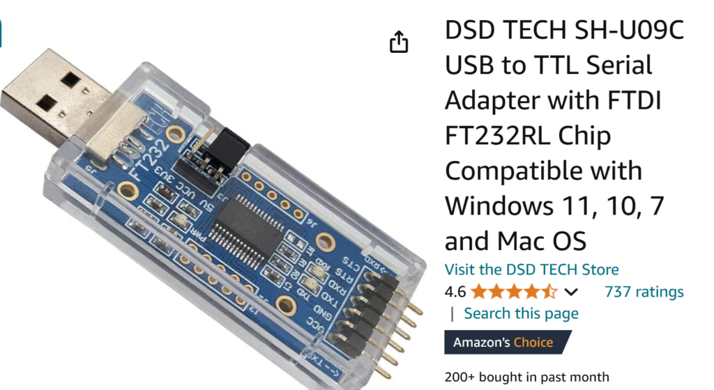
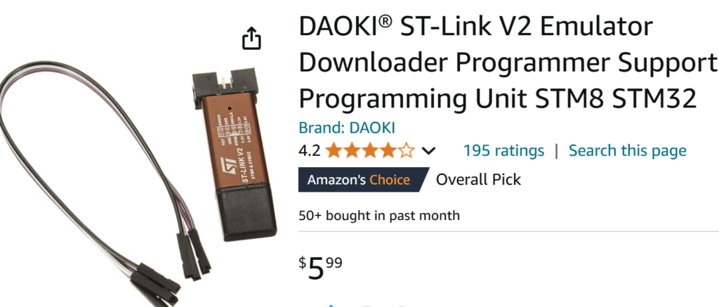
In addition to the ‘hardware-facilitated’ workarounds, there are at least two different software implementations that allow Arduino programs to be uploaded via the USB port. Both of these require that a ‘bootloader’ be installed into the STM32* MCU. One implementation is the ‘Maple’ bootloader, which comes in two flavors – the ‘original Maple bootloader’ and a modification of the original Maple bootloader called ‘STM32duino-bootloader’, or ‘bootloader 2.0’.
Serial Adaptor Method
The FTDI (serial adaptor) method requires that the STM32* MCU be restarted in ‘native bootloader’ mode before attempting to program the device. This is accomplished (in the case of ‘blue pill’ devices) by moving the BOOT0 jumper from the ‘1’ setting to the ‘0’ setting, as shown below, and then pressing and releasing the RESET button:
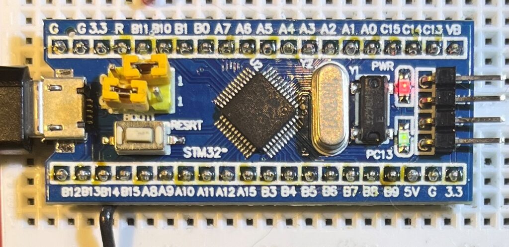
Then the program can be uploaded via the Arduino IDE (in my case I’m using the Visual Studio 2022 Visual Micro extension for Arduino, so my ‘look and feel’ will be different).
I found a really good tutorial for this ‘serial’ mode here. It was created in 2018, so it is a bit out of date with respect to the state of development of arduino-compatible bootloaders allowing program upload via USB, but is by far the clearest, most readable treatment of FTDI-based serial adaptor program uploads. I copied the wiring diagram shown below from this tutorial, in case it goes away at some point:
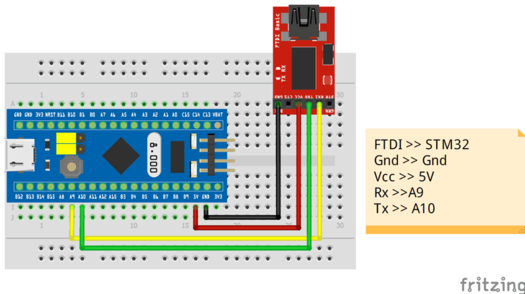
The process for upload using Arduino and a serial adaptor for program upload described here assumes you have the Arduino IDE installed and have the STM32 family of boards installed in the Arduino IDE. The procedure for installing the board information varies depending on the Arduino IDE version (I’m using Arduino 2 with the Visual Micro extension to Visual Studion 2022).
- Wire up the blue pill in accordance with the above diagram, and connect a USB cable from the adaptor to your PC. Note the port number associated with this connection
- Select the ‘serial’ upload method and the port number from above, as shown in the screenshot below
- Move the blue pill BOOT0 jumper from ‘0’ to ‘1’ and press/release the RESET button. This places the MCU in ‘Program’ mode using the built-in uploader.
- Compile/Upload the desired Arduino program. I strongly suggest you start with a simple ‘blink’ program. You should see the upload progress from 0 to 100%. If you don’t see upload progress, you have something wrong.
- Move the BOOT0 jumper from ‘1’ back to ‘0’ and press/release RESET. Moving the jumper places the MCU back in ‘user’ mode and pressing/releasing RESET will start your user program running. Note that in my experience, the user program will start right away, even with the BOOT0 jumper in the ‘1’ position, but you must actually move the jumper or the next time you cycle power or press/release the RESET button the MCU will come back up in ‘Program’ mode and your user program will not run.
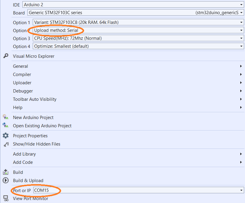
The output from a successful compile/upload cycle is shown below:
|
1 2 3 4 5 6 7 8 9 10 11 12 13 14 15 16 17 18 19 20 21 22 23 24 25 26 27 28 29 30 31 32 33 34 35 36 37 38 39 40 41 42 43 44 45 46 47 48 49 50 51 52 53 54 55 56 57 58 59 60 61 62 63 64 65 66 67 68 69 70 |
Compiling 'BluePill' for 'Generic STM32F103C series(stm32duino_genericSTM32F103C)' Program size: 11840 bytes (used 18% of a 65536 byte maximum) (0.18 secs) Minimum Memory Usage: 1432 bytes (7% of a 20480 byte maximum) Uploading 'BluePill' to 'Generic STM32F103C series(stm32duino_genericSTM32F103C)' using 'COM15' Resetting to bootloader via Serial stm32flash 0.4 http://stm32flash.googlecode.com/ Using Parser : Raw BINARY Interface serial_w32: 115200 8E1 Version : 0x22 Option 1 : 0x00 Option 2 : 0x00 Device ID : 0x0410 (Medium-density) - RAM : 20KiB (512b reserved by bootloader) - Flash : 128KiB (sector size: 4x1024) - Option RAM : 16b - System RAM : 2KiB Write to memory Erasing memory Wrote address 0x08000100 (2.16%) Wrote address 0x08000200 (4.32%) Wrote address 0x08000300 (6.49%) Wrote address 0x08000400 (8.65%) Wrote address 0x08000500 (10.81%) Wrote address 0x08000600 (12.97%) Wrote address 0x08000700 (15.14%) Wrote address 0x08000800 (17.30%) Wrote address 0x08000900 (19.46%) Wrote address 0x08000a00 (21.62%) Wrote address 0x08000b00 (23.78%) Wrote address 0x08000c00 (25.95%) Wrote address 0x08000d00 (28.11%) Wrote address 0x08000e00 (30.27%) Wrote address 0x08000f00 (32.43%) Wrote address 0x08001000 (34.59%) Wrote address 0x08001100 (36.76%) Wrote address 0x08001200 (38.92%) Wrote address 0x08001300 (41.08%) Wrote address 0x08001400 (43.24%) Wrote address 0x08001500 (45.41%) Wrote address 0x08001600 (47.57%) Wrote address 0x08001700 (49.73%) Wrote address 0x08001800 (51.89%) Wrote address 0x08001900 (54.05%) Wrote address 0x08001a00 (56.22%) Wrote address 0x08001b00 (58.38%) Wrote address 0x08001c00 (60.54%) Wrote address 0x08001d00 (62.70%) Wrote address 0x08001e00 (64.86%) Wrote address 0x08001f00 (67.03%) Wrote address 0x08002000 (69.19%) Wrote address 0x08002100 (71.35%) Wrote address 0x08002200 (73.51%) Wrote address 0x08002300 (75.68%) Wrote address 0x08002400 (77.84%) Wrote address 0x08002500 (80.00%) Wrote address 0x08002600 (82.16%) Wrote address 0x08002700 (84.32%) Wrote address 0x08002800 (86.49%) Wrote address 0x08002900 (88.65%) Wrote address 0x08002a00 (90.81%) Wrote address 0x08002b00 (92.97%) Wrote address 0x08002c00 (95.14%) Wrote address 0x08002d00 (97.30%) Wrote address 0x08002e00 (99.46%) Wrote address 0x08002e40 (100.00%) Done. Starting execution at address 0x08000000... done. The upload process has finished. |
13 November 2024 Update:
OK, now I have learned how to upload Arduino programs to my ‘blue pill’ STMF103C -based boards. I can program it using an ST-LINK adaptor, and I can program it using a FTDI serial adaptor. Both of these options rely on STMicro’s internal bootloader to transfer a program binary to flash memory.
After successfully programming both my ‘blue pill’ devices, I decided to try my luck with my 3D printer motherboard. This board has both serial (UART) and SWD (ST-LINK) connectors, and I chose the SWD connector option. My first try at this failed, at which point I used vMicro’s Visual Micro Explorer to check for a STM32F40xx board selection, found the ‘STM32F4xx’ selection, and installed it.
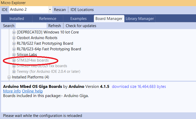
This then shows up as ‘STM32 Discovery F407’ in the board selection entry field.
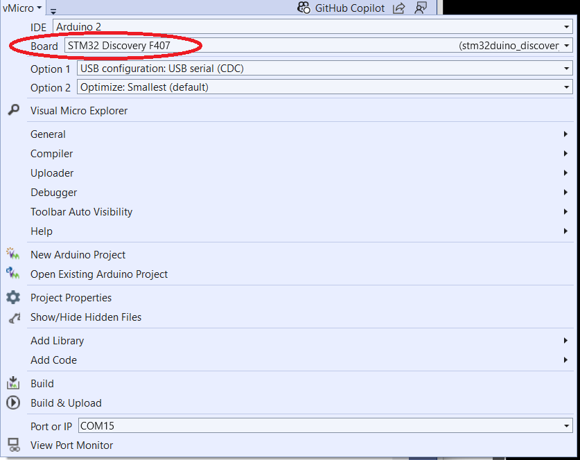
With this configuration, I was able to program a variation on my blue pill ‘blink’ program to direct a square wave to the buzzer on the motherboard. Amazingly, this worked like a champ, proving that my motherboard has not been bricked at all – Yay!!
Here’s the compiler/uploader output:
|
1 2 3 4 5 6 7 8 9 10 11 12 13 14 15 16 17 18 19 20 21 22 23 24 25 26 27 28 29 30 31 32 33 34 35 |
Program BluePill size: 20532 bytes (used 2% of a 1048576 byte maximum) (1.82 secs) Minimum Memory Usage: 5504 bytes (4% of a 131072 byte maximum) # Copy build result to 'Project>Property Pages>Intermediate Directory' # Destination: "file:///C:/Users/Frank/Documents/Arduino/BluePill/BluePill/obj/ARM64/Release/" Uploading 'BluePill' to 'STM32 Discovery F407(stm32duino_discovery_f407)' using 'COM15' Uploader started for board STM32 Discovery F407(stm32duino_discovery_f407) Upload method will be: bootloader Uploading via Bootloader c:\Users\Frank\AppData\Local\Arduino15\packages\stm32duino\tools\stm32tools\2022.9.26\win\stlink_upload.bat "C:\Users\Frank\AppData\Local\Temp\VMBuilds\BluePill\stm32duino_discovery_f407\Release/BluePill.ino.bin" STM32 ST-LINK CLI v3.3.0.0 The upload process has finished. STM32 ST-LINK Command Line Interface ST-LINK SN: 29003F000E2D343632525544 ST-LINK Firmware version: V2J37S7 (Need Update) Connected via SWD. SWD Frequency = 4000K. Target voltage = 3.2 V Connection mode: Normal Reset mode: Software reset Device ID: 0x413 Device flash Size: 1024 Kbytes Device family: STM32F405xx/F407xx/F415xx/F417xx Loading file... Flash Programming: File : C:\Users\Frank\AppData\Local\Temp\VMBuilds\BluePill\stm32duino_discovery_f407\Release\BluePill.ino.bin Address : 0x08000000 Memory programming... ±±±±±±±±±±±±±±±±±±±±±±±±±±±±±±±±±±±±±±±±±±±±±±±±±± 0% 0%ÛÛÛÛÛÛÛÛÛÛÛÛÛÛÛÛÛÛÛÛÛÛÛÛÛÛÛÛÛÛÛÛÛÛÛÛÛÛÛÛÛÛÛÛÛÛÛÛÛÛ 100% Memory programmed in 0s and 890ms. Programming Complete. MCU Reset. Application started. |
Looking through the above output, I realized that this line:
|
1 |
c:\Users\Frank\AppData\Local\Arduino15\packages\stm32duino\tools\stm32tools\2022.9.26\win\stlink_upload.bat "C:\Users\Frank\AppData\Local\Temp\VMBuilds\BluePill\stm32duino_discovery_f407\Release/BluePill.ino.bin" |
which points to ‘stlink_upload.bat’ shown below:
|
1 2 3 4 5 6 7 8 9 10 11 12 13 14 15 16 17 |
@echo off rem: Note %~dp0 get path of this batch file rem: Need to change drive if My Documents is on a drive other than C: set driverLetter=%~dp0 set driverLetter=%driverLetter:~0,2% %driverLetter% cd %~dp0 rem: the two line below are needed to fix path issues with incorrect slashes before the bin file name set str=%1 set str=%str:/=\% rem: ------------- use STLINK CLI stlink\ST-LINK_CLI.exe -c SWD -P %str% 0x8000000 -Rst -Run -NoPrompt rem: Using the open source texane-stlink instead of the proprietary STM stlink exe rem:texane-stlink\st-flash.exe write %str% 0x8000000 |
Is where ‘all the magic’ happens. After the user program is compiled into a binary (in this case ‘BluePill.ino.bin’) this file is passed to an open-source version of STM32’s ST-LINK program, which then writes the binary file to STM32 flash memory starting at location 0x8000000.
I think this means that I could just as easily use ST-LINK on my PC to upload BluePill.ino.bin to 0x8000000.
YESSSSS! Using STM’s ST-LINK on my laptop (for some reason I can’t get STM32CubeProgrammer to work) I uploaded BluePill.ino.bin to the FFCP2 board, and it worked!
Next, I tried uploading the original FFCP2 firmware onto the device, hoping that I would then have *two* working FFCP2 motherboards. Unfortunately, although the upload succeeded, and I was able to verify that the contents of the MCU’s flash memory were identical to the binary file I got from FlashForge Tech support, I saw no indication that the program was actually running (even though no actual printer hardware was connected, I had expected that at least the display and the buzzer would be active).
Alas, now I can no longer connect to the board using ST-LINK 🙁 I fear my journey is over, and not in a good way 🙁🙁🙁🙁