In my previous post on this topic, I described my efforts to use the Arduino PID library to manage turns with Wall-E2, my autonomous wall following robot. This post talks about a problem I encountered with the PID library when used in a system that uses an external timing source, like the TIMER5 ISR in my system and a PID input that depends on accurate timing, such as my turn-rate input.
In my autonomous wall-following robot project, I use TIMER5 on the Arduino Mega 2560 to generate an interrupt ever 100 mSec, and update all time-sensitive parameters in the ISR. These include results from all seven VL53L0X ToF distance sensors, the front-mounted LIDAR, and heading information from a MP6050 IMU. This simplifies the software immensely, as now the latest information is available throughout the code, and encapsulates all sensor-related calls to a single routine.
In my initial efforts at turn-rate tuning using the Arduino PID library, I computed the turn rate in the ISR by simply using
1
turn_rate=10*curr_hdg-prev_hdg//appropriately adjusted for 0-180 transitions, etc.
This actually worked because, the ISR frequency and the PID::Compute() frequency were more or less the same. However, since the two time intervals are independent of each other there could be a phase shift, which might drift slowly over time. Also, if either timer interval is changed sometime down the road, the system behavior could change dramatically. I thought I had figured out how to handle this issue by moving the turn-rate computation inside the PID::Compute() function block, as shown below
In a typical PID use case, you see code like the following:
1
2
3
4
5
6
7
if(myPID.Compute())
{
//compute the new turn rate
//use the PID output term to control something
...
...
}
After making the above change, I started getting really weird behavior, and all my efforts at PID tuning failed miserably. After a LOT of troubleshooting and head-scratching, I finally figured out what was happening. In the above code configuration, the PID generates a new output value BEFORE the new turn rate is computed, so the PID is always operating on information that is at least 100mSec old – not a good way to run a railroad!
Some of the PID documentation I researched said (or at least implied) that by setting the PID’s sample time to zero using PID::SetSampleTime(0), that Compute() would actually produce a new output value every time it was called. This meant that I could do something like the following:
1
2
3
4
5
6
7
8
9
10
11
12
13
14
15
16
17
if(bTimeForNavUpdate)//set true in ISR
{
bTimeForNavUpdate=false;
//4/28/21 now time interval is constant at ~100mSec
//11/14/20 need to handle -179 to +179 transition
floatdeltaDeg=IMUHdgValDeg-prev_hdg;
deltaDeg=(deltaDeg>180)?deltaDeg-360:deltaDeg;
deltaDeg=(deltaDeg<-180)?deltaDeg+360:deltaDeg;
TurnRateVal=10*abs(deltaDeg);//now time interval is constant 1/10 sec
TurnRatePID.Compute();//04/10/21 SampleTime == 0 so now this updates every time
Great idea, but it didn’t work! After some more troubleshooting and head-scratching, I finally realized that the PID::SetSampleTime() function specifically disallows a value of zero, as it would cause the ‘D’ term to go to infinity – oops! Here’s the relevant code
1
2
3
4
5
6
7
8
9
10
11
voidPID::SetSampleTime(intNewSampleTime)
{
if(NewSampleTime>0)
{
doubleratio=(double)NewSampleTime
/(double)SampleTime;
ki *=ratio;
kd/=ratio;
SampleTime=(unsignedlong)NewSampleTime;
}
}
As can be seen from the above, an argument of zero is simply ignored, and the sample time remains unchanged. When I pointed this out to the developer, he said this was by design, as the ‘ratio’ calculation above would be undefined for an input argument of zero. This is certainly a valid point, but makes it impossible to synch the PID to an external master clock – bummer!
After some more thought, I modified my copy of PID.cpp as follows:
1
2
3
4
5
6
7
8
9
10
11
12
13
14
voidPID::SetSampleTime(intNewSampleTime)
{
Serial.println("In PID::SetSampleTime with NewSampleTime = ");Serial.println(NewSampleTime);
if(NewSampleTime>0)
{
doubleratio=(double)NewSampleTime
/(double)SampleTime;
ki *=ratio;
kd/=ratio;
//SampleTime = (unsigned long)NewSampleTime;
}
SampleTime=(unsignedlong)NewSampleTime;
}
By moving the
SampleTime=(unsignedlong)NewSampleTime; line out of the ‘if’ block, I can now set the sample time to zero without causing problems with the value of ‘ratio’. Now PID::Compute() will generate a new output value every time it is called, which synchs the PID engine with the program’s master timing source – yay!
I tried out a slightly modified version of this technique on my small 2-wheel robot. The two-wheeler uses an Arduino Uno instead of a Mega, so I didn’t use a TIMER interrupt. Instead I used the ‘elapsedMillisecond’ library and set up an elapsed time of 100 mSec, and also modified the program to turn indefinitely at the desired turn rate in deg/sec.
I experimented with two different methods for controlling the turn rate – a ‘PWM’ method where the wheel motors are pulsed at full speed for a variable pulse width, and a ‘direct’ method where the wheel motor speeds are varied directly to achieve the desired turn rate. I thought the PWM method might work better on a heavier robot for smaller angle turns as there is quite a bit of inertia to overcome, but the ‘direct’ method might be more accurate.
Here’s the code for the ‘direct’ method, where the wheel speeds are varied with
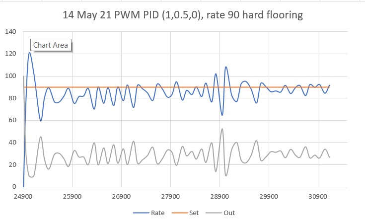
Here’s a short video showing the two-wheel robot doing a spin turn using the PWM technique with a desired turn rate of 90 deg/sec, using PID = (1,0.5,0).
The average turn rate for the entire run was about 85 deg/sec.
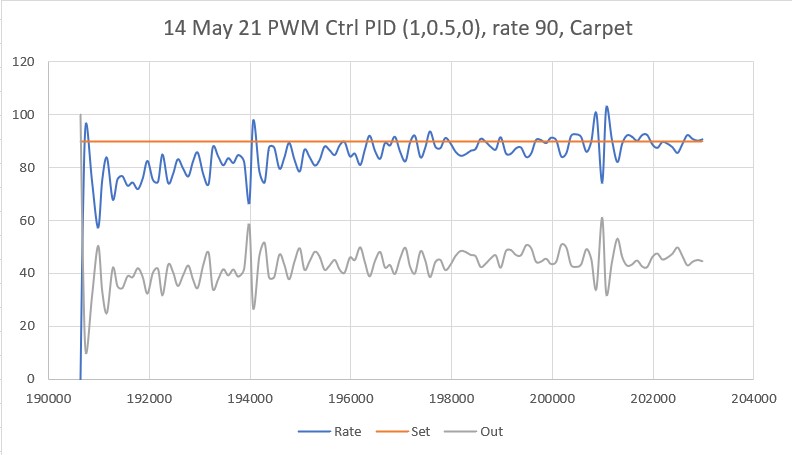
Here’s another run, this time on carpet:
Average turn rate for the entire run was about 85 deg/sec
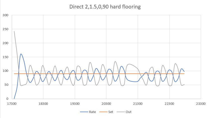
Here’s some data from the ‘direct’ method, on hard flooring
Average turn rate was ~ 85 deg/sec
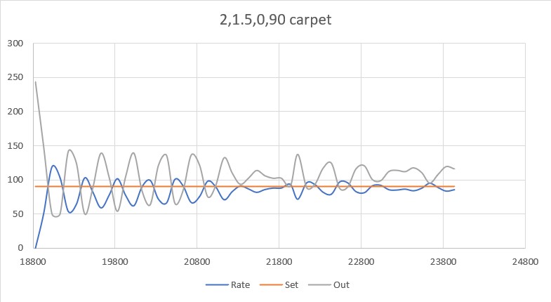
And on carpet
Average turn rate ~83 deg/sec
So, it appears that either the PWM or ‘direct’ methods are effective in controlling the turn rate, and I don’t really see any huge difference between them. I guess the PWM method might be a little more effective with the 4-wheel robot caused by the wheels having to slide sideways while turning.
Pingback: Turn Rate PID Tuning, Part III | Paynter's Palace