Posted 06/28/16
In my last post on this subject, I used my new Magnetometer to generate calibration matrix/center offset values for my Mongoose IMU (which uses a HMC5883 3-axis magnetometer), in a ‘free space’ (no nearby magnetic interferers) environment, and showed that I could incorporate these values into the Mongoose’s firmware. In this post, I describe my efforts to calibrate the same Mongoose IMU, but now mounted on Wall-E2, my 4WD wall-following robot.
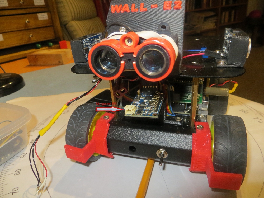
A long time ago, in a galaxy far, far away (actually 3 months ago, in the exact same galaxy), I had the Mongoose IMU mounted on the front of my robot, as shown in the above image. Unfortunately, when I tried to use the heading data from the Mongoose (see Giving Wall-E2 a Sense of Direction, Part IV), it was readily apparent that something was badly wrong. Eventually I figured out that the problem was the magnetic fields associated with the drive motors that were causing the problem, and I wouldn’t be able to do much about that without some sort of calibration exercise. After this realization I tried, unsuccessfully, to find a magnetometer calibration tool that I liked. Failing that, I wrote my own (twice!), winding up with the WPF-based application described in ‘Magnetometer Calibration, Part III‘.
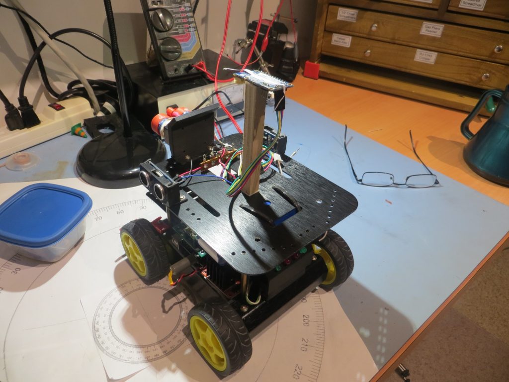
So, now the idea is to re-mount the Mongoose IMU on Wall-E2, and use my newly-created calibration tool to compensate for the magnetic interference generated by the DC motors and operating currents. As a first step in that direction, I decided to mount the IMU on a wooden stalk on the top of the robot, thereby gaining as much separation from the motors and other interferers as possible. If this works, then I will try to reduce the height of the stalk as much as possible.
The image below shows the initial mounting setup.
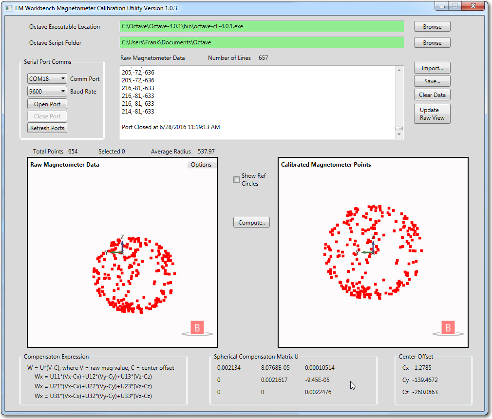
With the Mongoose mounted as shown, I used my magnetometer calibration tool to generate a calibration matrix and center offset, as shown in the following image.


