Posted 28 September 2024
I’ve had my Flashforge Creator Pro 2 (FFCP2) IDEX 3D Printer for about three years now, and it is my go-to printer for anything requiring internal support structures. For instance, this model is a pill dispenser that screws onto a pill bottle and dispenses one pill at a time.
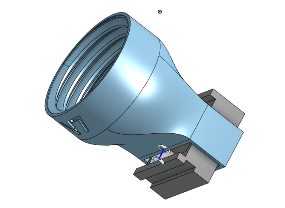
The dispenser has a slide mechanism (colored grey above) that allows one pill/caplet to drop down from the bottle into a slot when the slide is positioned at one end of its travel. The captured pill is then dropped out of the mechanism when the slide is move to the other extreme. Printing this as a single piece requires the use of a dissolvable support filament, which in practice requires a dual extruder printer like the FFCP2. Although in theory this could be done on a single extruder printer with a ‘multi-material’ setup like the Prusa XL or the Bambu X1, in practice it is extremely difficult because the without a LOT of purging, the dissolvable filament contaminates the extruder head and weakens the print.
So I love my FFCP2 because it allows me to print things like the above pill dispenser, but I hate it because the supplied firmware is anything but elegant, and there have been no updates since I purchased it three years ago (and since it has been discontinued by the manufacturer, no updated are likely in the future either). However, a few days ago, while doing yet another futile search for FFCP2 firmware updates, I ran across this post, which claimed to have gotten Klipper to work on a FFCP2. At the time I wasn’t sure what ‘Klipper’ was, but after some research I realized this was what I was looking for – in spades! According to the Klipper Github page, it is hardware-agnostic 3-d printer firmware with the features described here.
Reading through the features list and the FAQ was more than a little overwhelming; I got lost pretty quickly trying to figure out what the heck this ‘Klipper’ stuff was doing. I think I finally figured out that ‘Klipper’ is a system composed of (at least) three parts, as shown below:
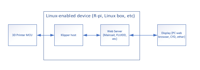
In the above diagram, the firmware in the 3D printer MCU is replaced by firmware that handles only low-level direct hardware control functions; all the calculations required for a successful print are moved to the Klipper host software on the Linux-enabled device (a Raspberry Pi or equivalent, or a Linux PC of some kind). This offloads most of the computational load from the 3D printer MCU allowing – at least in theory – the printer to actually run faster (although the physics of extrusion and motors will still limit the process). The Linux-enabled device also contains a web server (Mainsail or FLUIDD) that exposes 3D printer controls to the user, via any web browser or dedicated display like the very cool CYD program by Sims. The Klipper software in the Linux-enabled device is much more usable than my old Flashforge firmware, and since it is written in Python and is open-source, much easier to maintain/extend.
Progress to date:
Due to some hardware problems with my FFCP2, I haven’t yet gotten Klipper going on my printer. However, I have managed to connect to my printer’s MCU board using a cheap ST-LINK adaptor from Amazon and the ST-LINK Utility from ST Micro (ST Micro says that ST-LINK is now deprecated in favor of their STM32CubeProgrammer app, but I found that I could not connect to the FFCP2 MCU with this app, but I could with ST-LINK – go figure) . It took me a while to find my way around the ST-LINK utility, but I finally figured out that I could modify the default memory view ‘size’ parameter to capture more or less of the MCU’s flash memory. After a short conversation with ‘Guru’ at ST, I took his advice and expanded the ST-LINK memory view to the full 1MByte flash memory size of the STM32F407xx MCU on the FFCP2 motherboard, and then saved that image to a file for safe-keeping and, if necessary, reversion to the original firmware.
For the ‘Linux-enabled Device’, I decided to repurpose an old Dell Precision M6700 laptop that already had Debian Linux loaded from a previous project. After making sure that my Debian install was up to date, I followed the instructions in Evil Azrael’s Wiki to load Klipper onto the laptop. Here are some photos of the process:
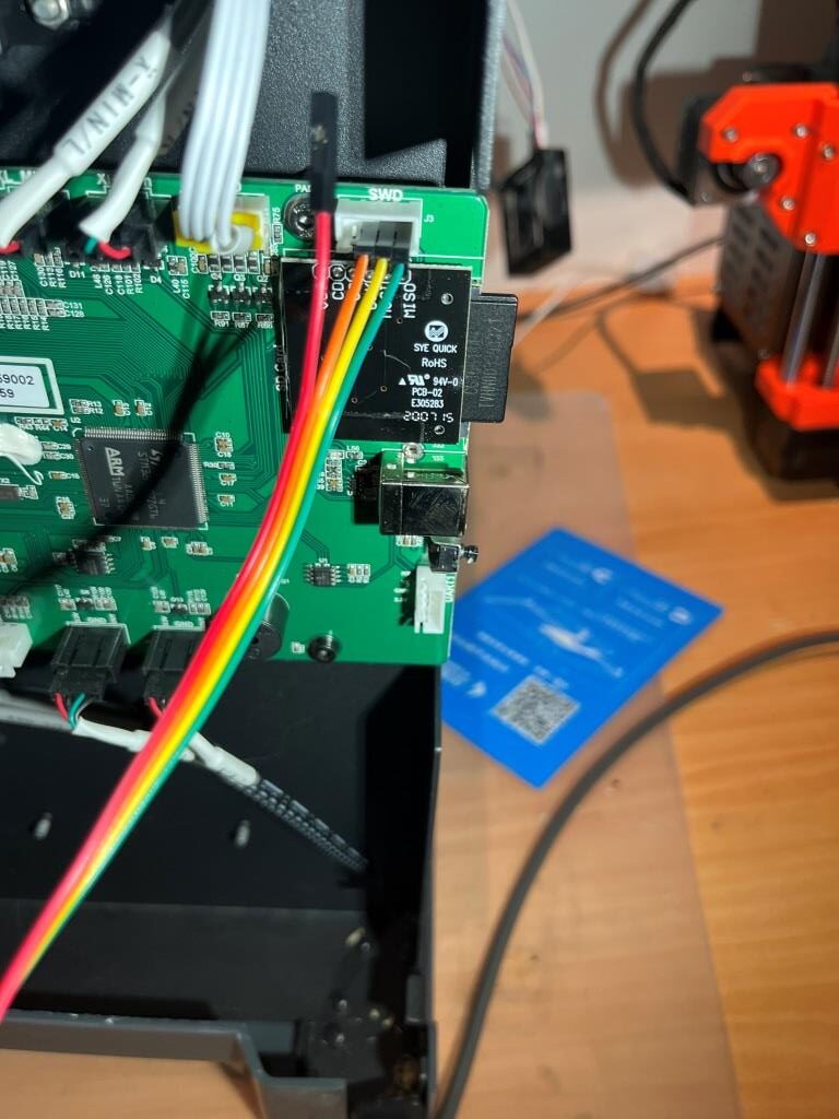
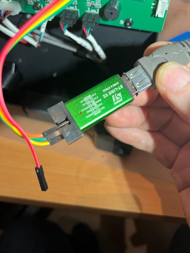
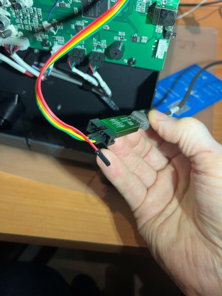
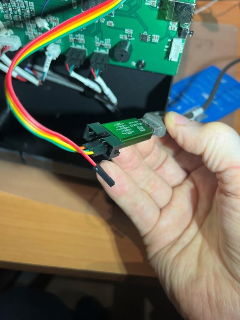
The connections are:
MCU SWD ST-LINK
GRN GND GND
YEL DIO SWDIO
ORG CLK SWCLK
At this point, I’m waiting on a part delivery to get my FFCP2 back in working order so I can finish my ‘Klipperization’ project, but I’m really looking forward to having access to a non-moronic printer control package.
24 October 2024 Update:
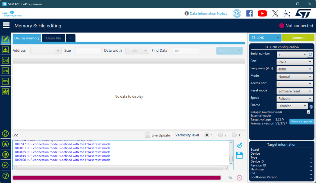
When I connected up my ST-LINK/USB adapter to my FFCP2 and my Win 11 laptop, I was unable to get ST’s ST-LINK utility to connect to the MCU – bummer! After verifying all the connections and trying different things (power-cycling and/or resetting the FFCP2, disconnecting/reconnecting the USB cable, etc) I still have been unable to connect. This is a serious bummer, as if I have ‘bricked’ my FFCP2 I have no idea what to do next. I posted to the ST forum, so I’ll see how that goes.
After some more research, I found this post describing how to force a firmware reload, as follows:
|
1 2 3 4 5 |
Download the zip and extract the .bin file. Then rename the .bin file to creatorp.bin. copy creatorp.bin to sys folder in the SD card. put SD card back in the printer and try to boot it. After it has installed and booted, you should go to settings and do factory reset. |
I did all this using the .BIN file I captured from the ST-micro MCU, but unfortunately the printer did not respond. I have also attempted to find the original factory firmware for this printer on the FlashForge support site, but that all seems to have disappeared. :(.
28 October 2024 Update:
After crying in my beer for a while, I started looking for alternative methods for regaining access to my ‘bricked’ STM32F407 motherboard processor. I figured ST-Micro had to have some way of doing this, so I started poking around there. Eventually I came across this article that described the process, as shown below:
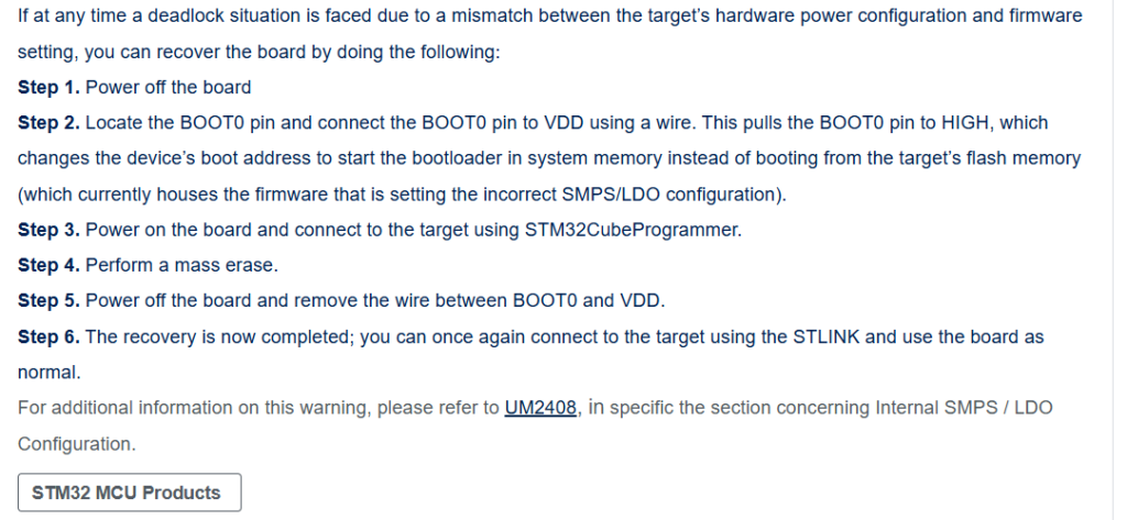
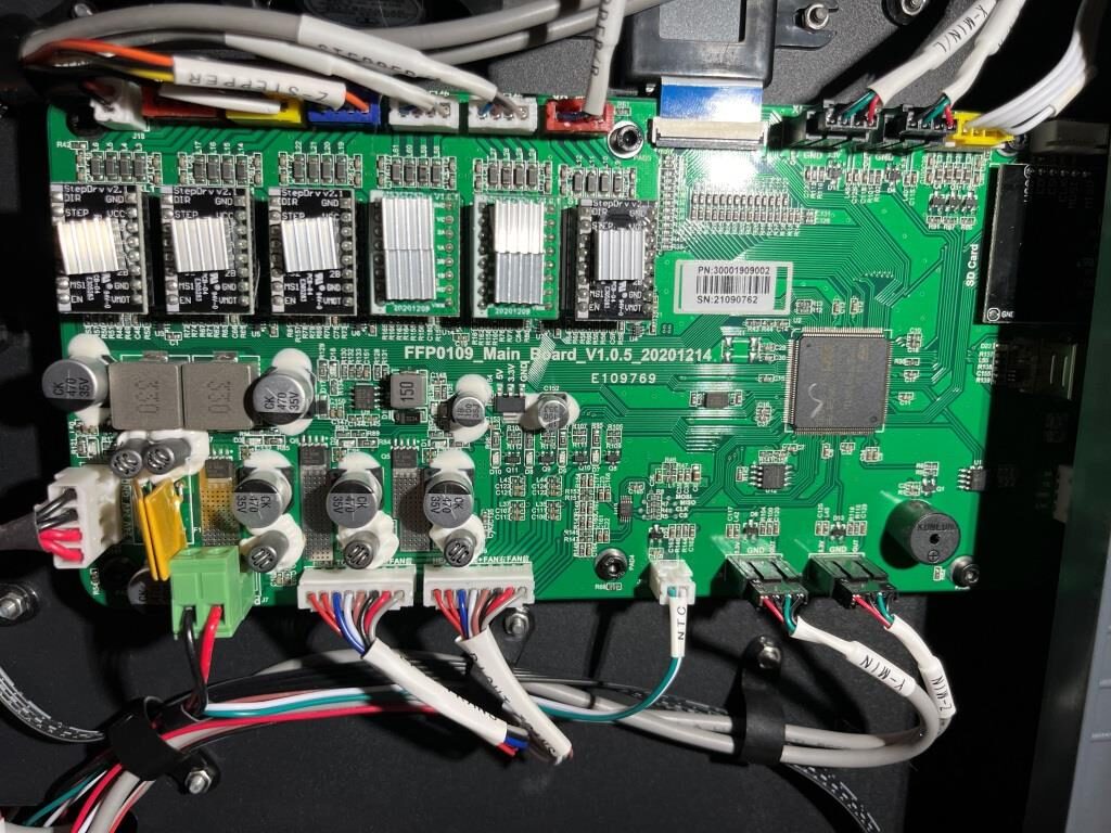
So I started looking for BOOT0 on my motherboard – a process that was hindered by the lack of a schematic. Apparently FlashForge printers (including the FFCP2) are ‘closed’ products and schematics are hard/impossible to find. Fortunately for me, I had developed a bit of rapport with the FlashForge tech support team, and I pleaded to them for a copy of the schematic, pointing out that since the FFCP2 is no longer supported by FlashForge, there shouldn’t be any reason to continue to hold onto the schematics. To my amazement, this actually worked, and I got an email back with the board schematic as a JPG attachment – yay!
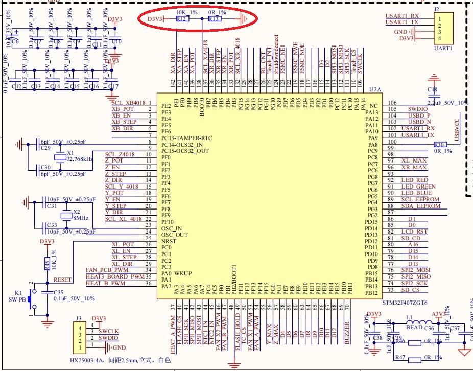
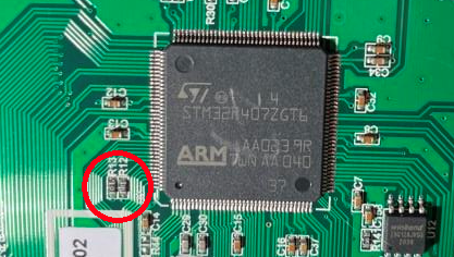
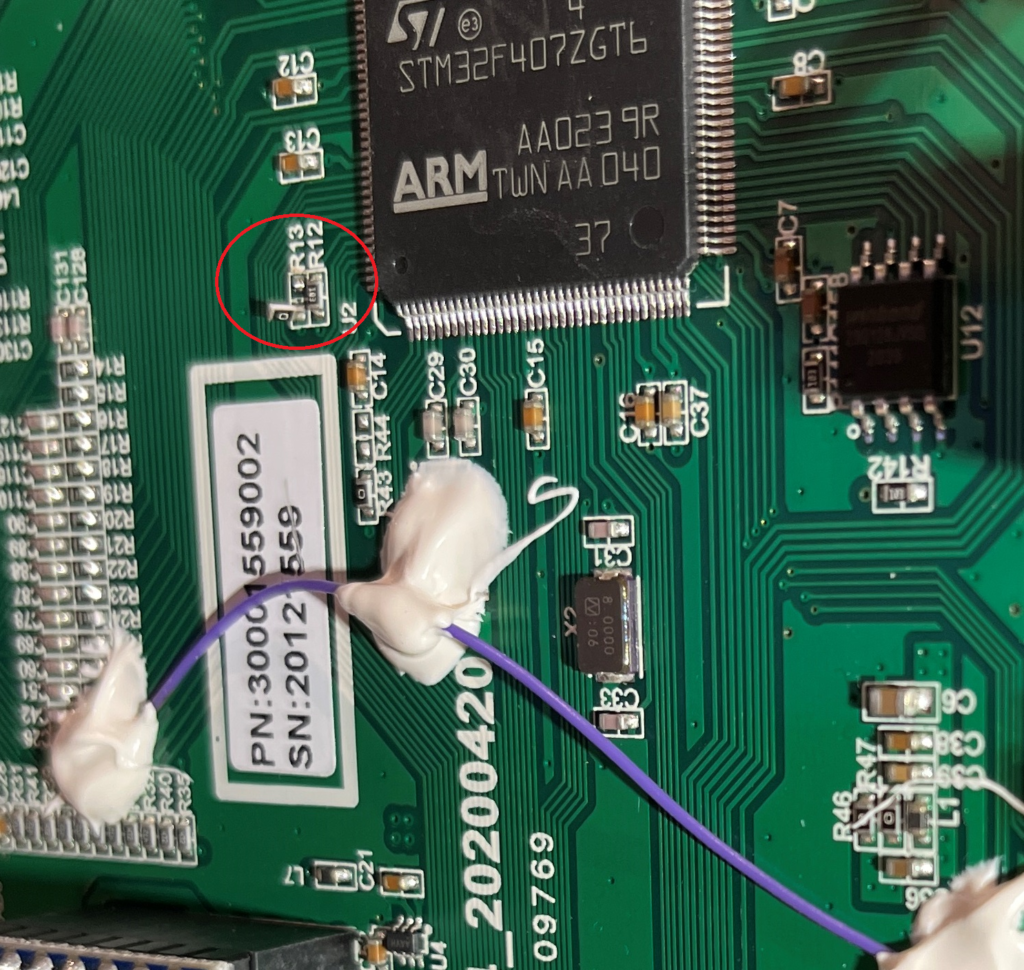
As can be seen from the above schematic and photo, BOOT0 is connected to the resistive voltage divider R12/R13, and the value of R13 is 0Ω (short circuit) holding BOOT0 to GND. To raise BOOT0 to VDD (3.3V), all I have to do is remove R13 from the circuit and R1 (10K) will pull it up to VDD. Here is a photo showing R13 removed from the circuit.
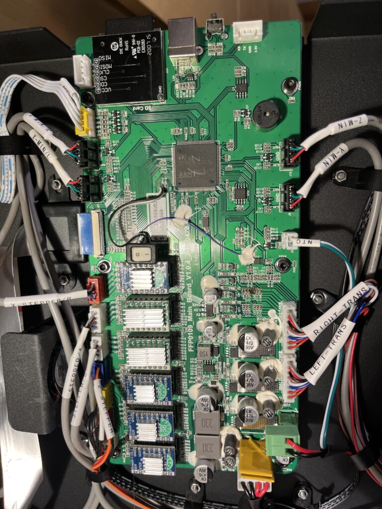
After powering up the printer, I found that I was indeed able to connect to it using ST-LINK (ST32CubeProgrammer still doesn’t). Here’s a photo of the motherboard with a small SPST switch installed to make switching BOOT0 high/low easier
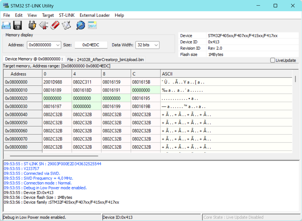
But not with STM32CubeProgrammer
31 October 2024 Update:
Well, bad news; although I could regain SWD connection using the BOOT0 trick, I was unable to figure out how to get my original FFCP2 firmware back onto the STM32 MCU. I can load the firmware (or at least ST-LINK utility says I loaded the firmware), but the printer won’t come back up properly after the load. I eventually succumbed and installed a new motherboard (ouch!$$$). The new motherboard seems to be from a different production run, as the ugly jumper wire is now missing.
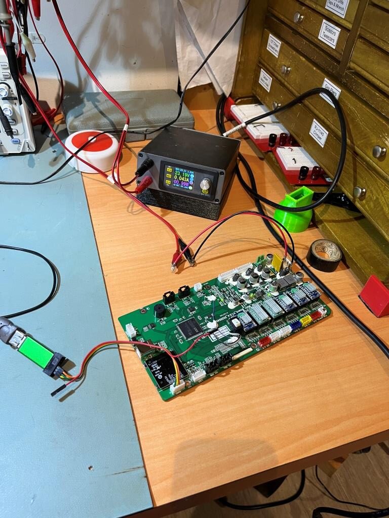
As an experiment, I hooked up my old motherboard to my lab power supply set for 24 (actually 23.19), and was able to connect to it using ST-LINK Utility on my windows 11 box and a ‘clone’ ST-LINK adaptor. Interestingly, I was unable to connect using STM32CubeProgrammer on either my Win11 box or my Linux box. Maybe I have to have a ‘genuine’ ST-LINK adaptor for that magic to work?
Stay tuned!
Frank