Posted 31 July 2024
I’ve been a 3D printer enthusiast for many years now and have accumulated a fair collection of filaments for my Prusa MK4 and Flashforge Creator Pro IDEX printers. All these filament supplies are hygroscopic to one degree or another and so have to be kept in a low-humidity environment to avoid deterioration. Early on I created my own ‘low humidity storage bin’ using a large plastic storage tub and a 40W lightbulb with a custom-made temp/humidity meter, as shown in the following photo:
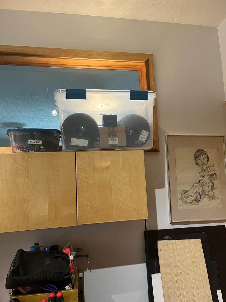
I adjusted the relative humidity to about 30% by creating and/or taping over holes in the plastic tub. This worked pretty well, but suffered from two significant drawbacks. First, the 40W lightbulbs are hard to find anymore, and they don’t last very long, so I have to keep replacing them. Secondly, the storage tub is mounted on a high shelf, so it is inconvenient to add or remove filament rolls. Also, the inconvenient placement means I often leave unused rolls out, and of course their printing performance slowly degrades – oops!
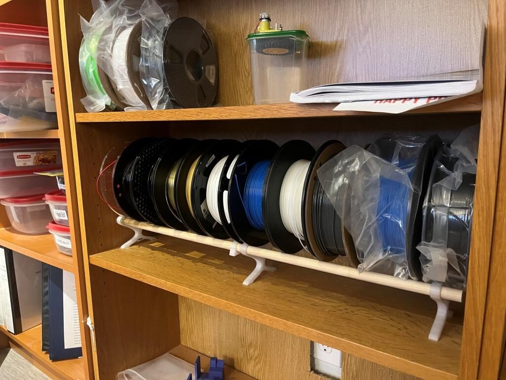
Coincidentally we had the floor in my office redone a couple of years ago, and in preparation for this I removed a lot of books from my wall of Ikea book shelves, and wound up with several empty sections. Over the last couple of years I have started storing unused filaments in those empty sections rather than in the dryer tub where they belong, as shown in the following photo:
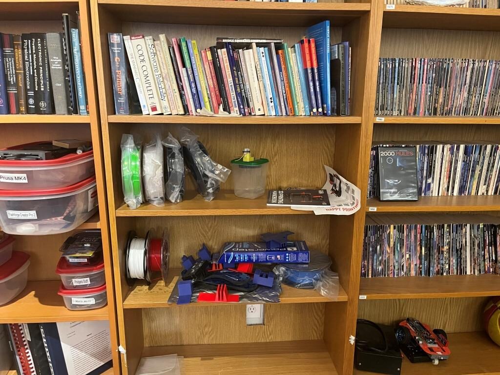
So, I had the brilliant (I hope!) idea that if I were to fabricate a transparent cover for one of the empty bookshelf sections and install some kind of heating element, I could transform my current room humidity filament storage into a much more convenient dry storage area.
My current filament dryer tub actually does a pretty good job of reducing the humidity using just a 40W lightbulb, so I reasoned that an approximately 40W heating element should do fine in my new design. I have an old Dell laptop power supply that supplies about 3A at 20V, so that should work as the power source. For the heating element I think I can use a length of #26 Nichrome wire as shown below:
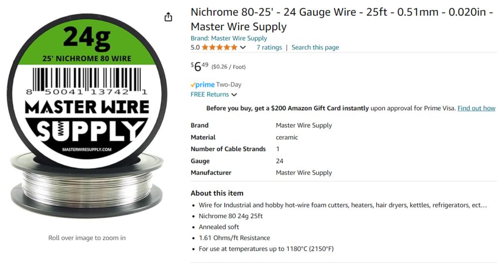
I need about 10Ω at 20V to produce 40W, so at 1.61Ω/ft, I need 10/1.61 = 6.2ft = 1.8m. The Ikea shelves are about 0.9m long, so I’ll need to do an ‘out-and-back’ run with the wire, but that will actually make wiring it up easier.
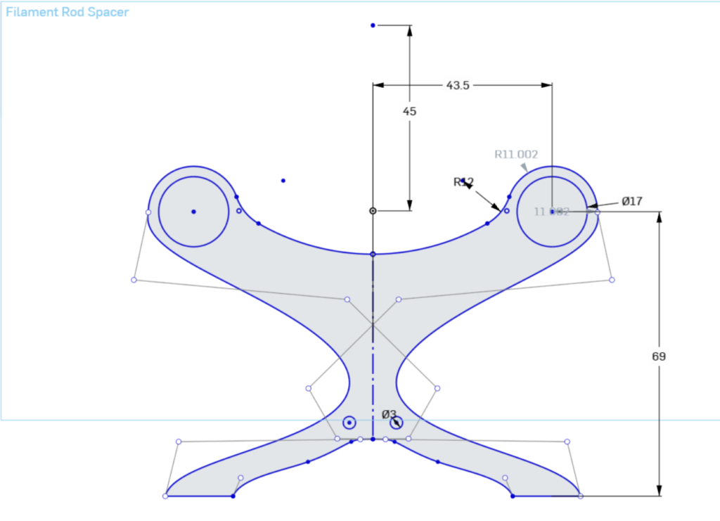
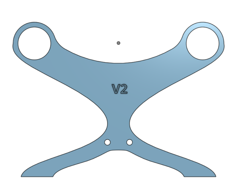
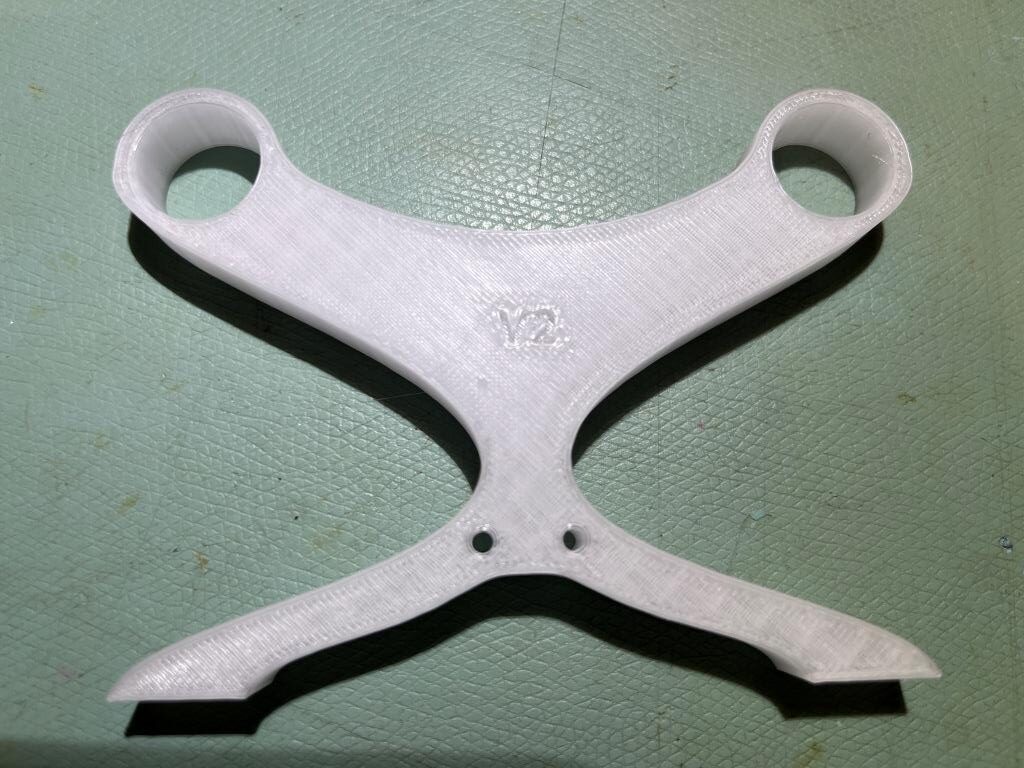
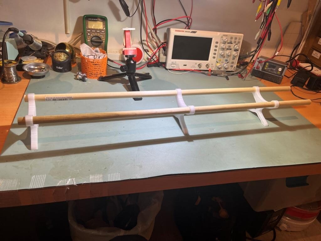
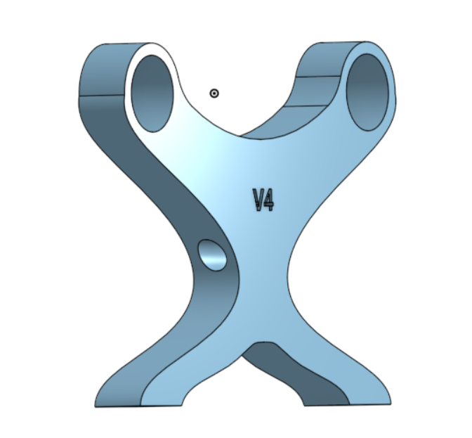
Yesterday I went down to Lowes and purchased a 6-foot (~2m) section of 5/8″ (16mm) wood dowel as the choice for supporting multiple filament reels. After some experimentation, I settled on 87mm spacing between rod centers, and designed a spacer piece in OnShape to space the dowels and lift the reels off the shelf surface by 69mm, as shown in the following OnShape sketch:
Nichrome Wire Heating Element:
I didn’t have a 20V 2A power supply handy and while my DIY lab power supply could easily get up to 20V, it couldn’t simultaneously deliver 2A – bummer. However, I did have an old-style PC power supply with multiple 12V 5A outputs, so I used it to see whether I could generate 40W-ish power dissipation in a length of nichrome wire. Using a 60cm length (approximately 4Ω) the 12V supply delivered approximately 3A (36W) and it definitely got quite hot (but not glowing hot). As part of the experiment, I placed one of my old V1 rod separator parts on the heated wire, and noted that the wire slightly melted into the PETG material, implying that I would need some heat-resistant insulation where the nichrome wire goes through the holes in the V2 rod separator part.
05 August 2024 Update:
My order of heat-resistant flexible tubing came in, so I was able to make some more progress:
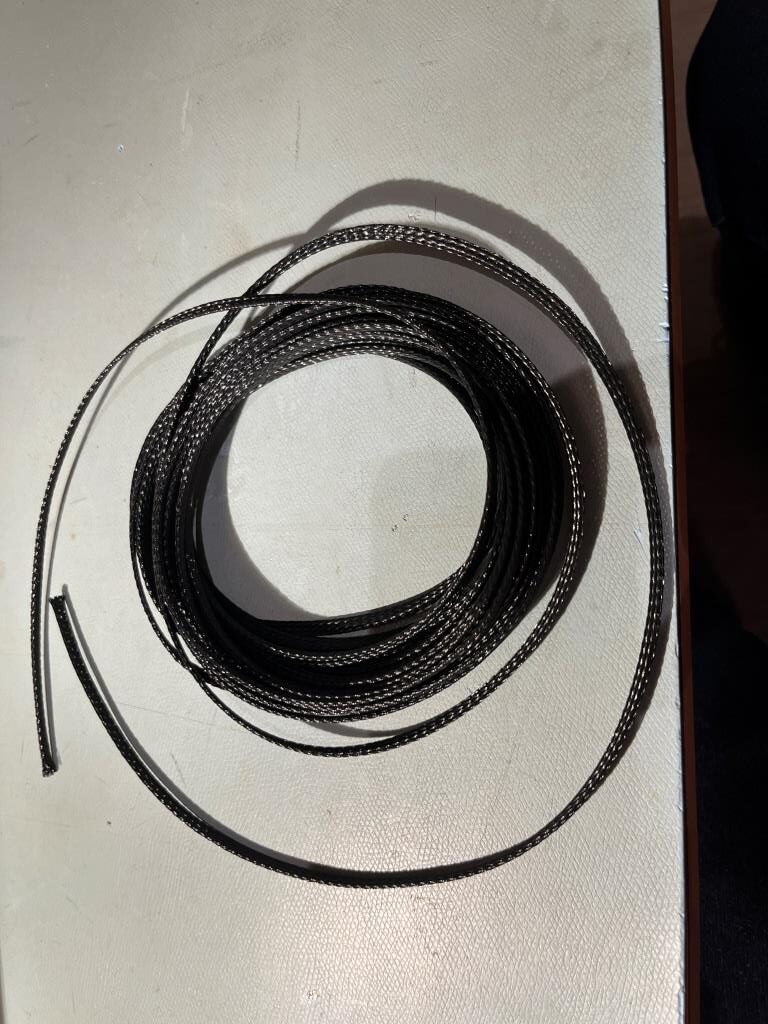
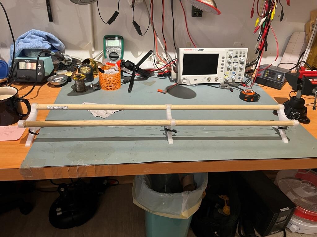
Unfortunately, I discovered that the sleeving was too large to fit through the holes I had designed into the V2 rod supports, so I wound up hot-gluing sections of the sleeving to the sided of the first and second supports, and then a longer section around the last support, as shown in the photo below:
12 August 2024 Update:
I finally got my MeanWell EPP-120S-24 open-frame power supply delivered, so I can now make some more progress on my bookshelf filament dryer project. While waiting for the power supply, I went ahead and acquired a piece of 1/4″ acrylic for use as the door, as shown below:
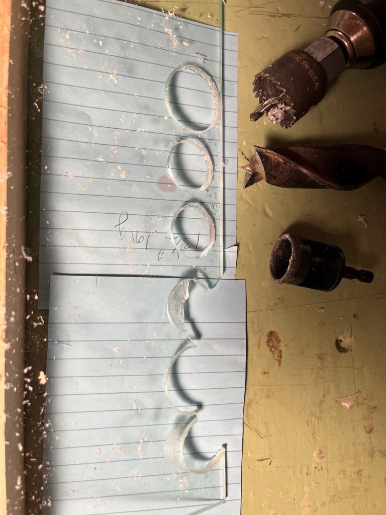
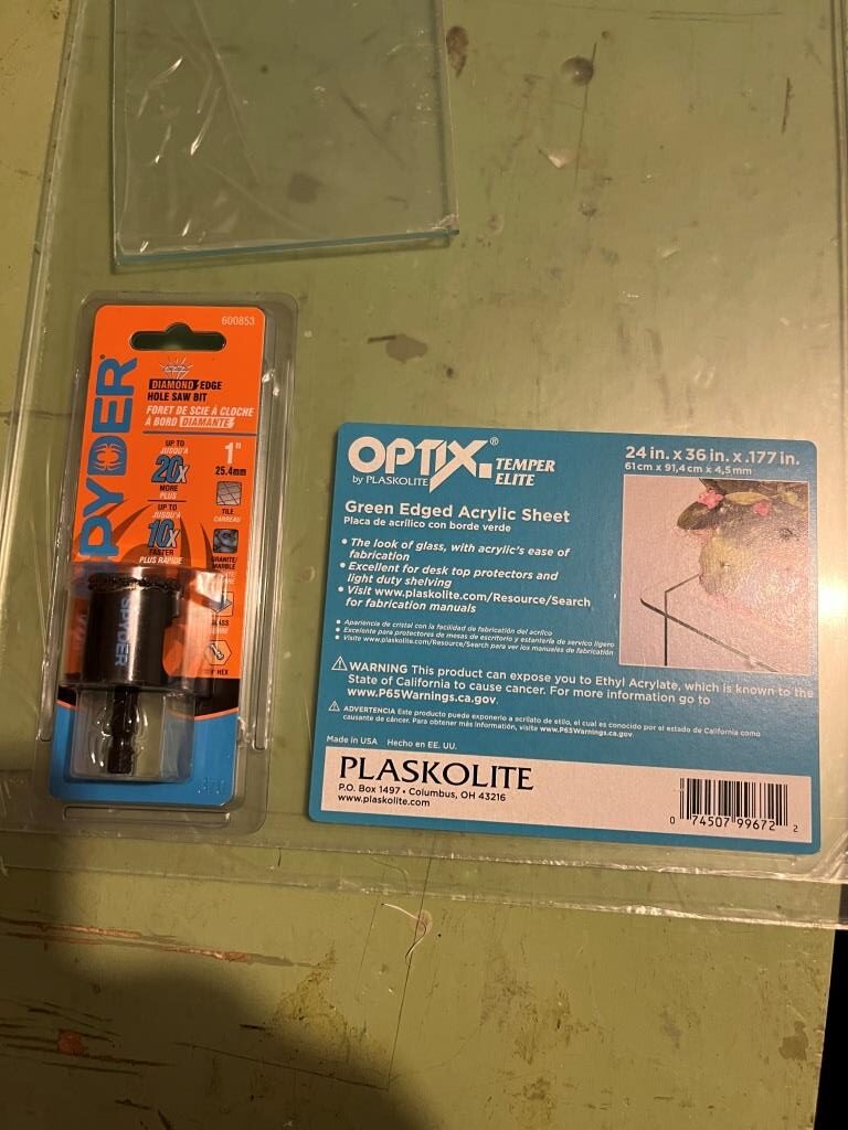
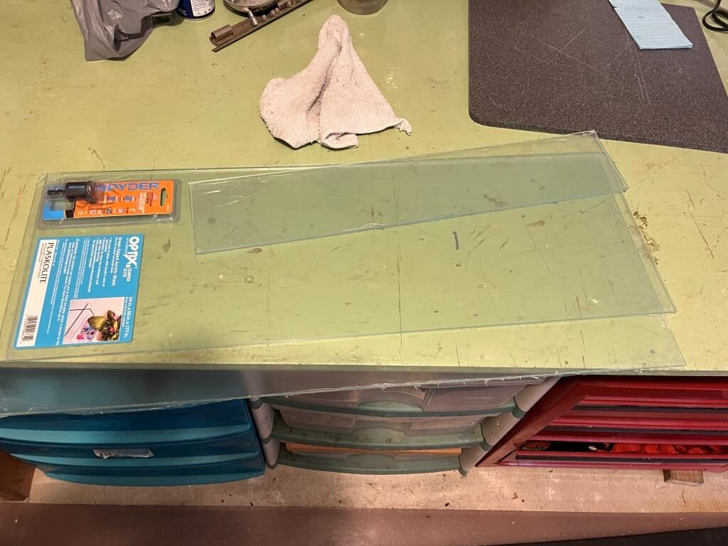
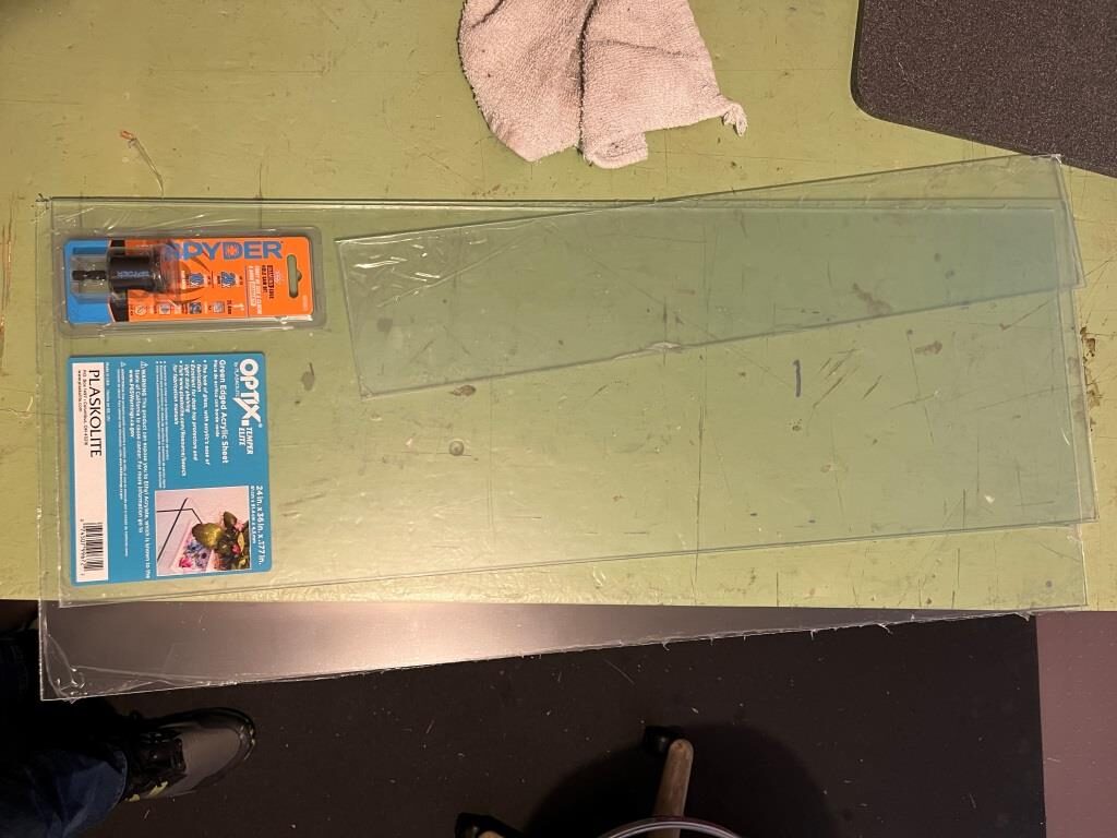
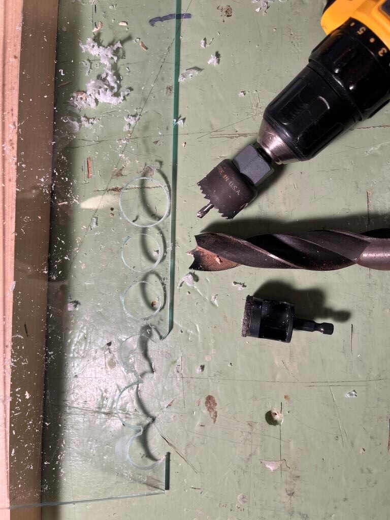
As shown above, I tried out my idea for adding temperature regulating holes to the design. I started with a very expensive ‘Ryder’ diamond-encrusted hole saw, guaranteed to cut anything. Unfortunately it didn’t incorporate any means to keep the saw cutting in the same place, so it immediately shot off to one side every time I tried to use it. Fortunately Lowes has a nice return policy, so I took it back. My other efforts were with a regular hole saw I had around with a 1/4″ centering drill, and this worked OK if not great. The other option was a 1″ wood drill as it has a nice centering tip. I found I could drill through most of the thickness on one side with the wood drill, and then, when the tip was all the way through, turn the piece over and drill out the rest. Both of these last two methods worked fairly well, but I discovered that each hole took a lot of work and sweat to get right, and the idea of drilling 8-10 holes (4-5 at bottom, 4-5 at top) wasn’t too appealing. For now I’m going to leave the holes out unless I see that they are needed.
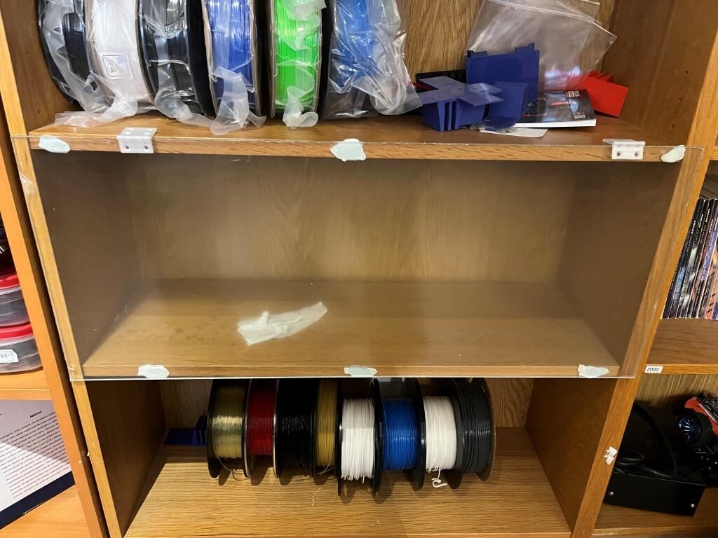
I installed the acrylic front piece on the bookshelf section using metal hinges. I wanted to use printed ones, but I found they weren’t strong enough (and the metal ones I got may be too lightweight as well – we’ll see)
Now that I have the power supply, time to test my theory about producing approximately 40W of heat from the nichrome wire length under the filament roll supports. I hooked up the supply to AC, checked the output (24V – yep), and connected it to the nichrome wire. As shown in the following photo, The supply held 24V and produced a little over 2A in the wire, for a power dissipation of about 50W – a little more than I had in my previous (40 lightbulb) setup, but should be OK.
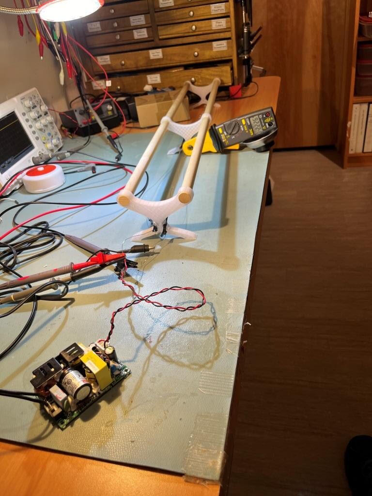
I let this run for about 30 minutes so far, and everything seems pretty stable. I did notice that the hot-glue material is getting somewhat soft where it was used to glue the pieces of heat-resistant sleeving to the rod separators, but nothing significant. I also noticed that the wire run is too loose at the moment, and part of the run rises up high enough to touch the bottom of a couple of the filament holders – definitely something I will have to address. Maybe I’ll need to print some more rod separators with larger holes that will accommodate the heat resistant material.
15 August 2024 Update:
Well, I soon discovered that the ‘heat-resistant’ tubing may have been heat-resistant, but it did not stand up well to actual use. When I started cutting it into small lengths, it almost immediately unraveled and became near useless. I also discovered that the hot-glue I was using to attach the tubing to the sides (the tubing was too large to go through the pre-printed holes) was melting and running all through the tubing, making it very difficult to remove the tubing from around the nichrome wire – yuk!
So, I came up with another brilliant plan; I found some high-temp silicone tubing on Amazon, 2mm OD, 1mm ID and my plan was to use this as a replacement, with the added advantage that the new tubing would fit through my pre-printed holes. My plan worked great, right up until the point where the nichrome wire got the tubing so hot that the wire/tubing combination melted right through the PETG printed supports – oops!
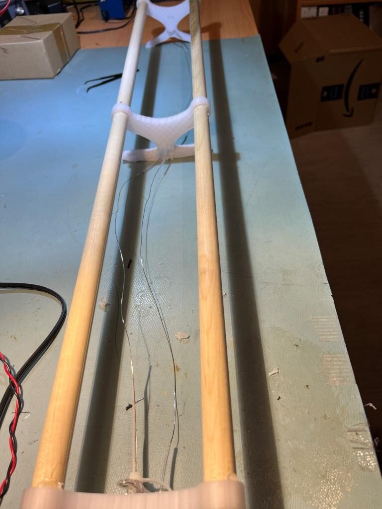
OK, so my next great idea is to use a 1/4″ (7mm) wood dowel rod mounted through each support with small holes drilled into the ends to pass the nichrome wire. The wood will insulate the wire from the PETG support, so no more melting —- maybe :).
This idea actually worked – except I forgot about that the wire had to somehow go around the end support without melting anything before being routed through the holes on the other side of the transverse support rods. The solution I finally came up with was to add a +/- 45º spread of rod segments around the end piece, as shown in the following photos
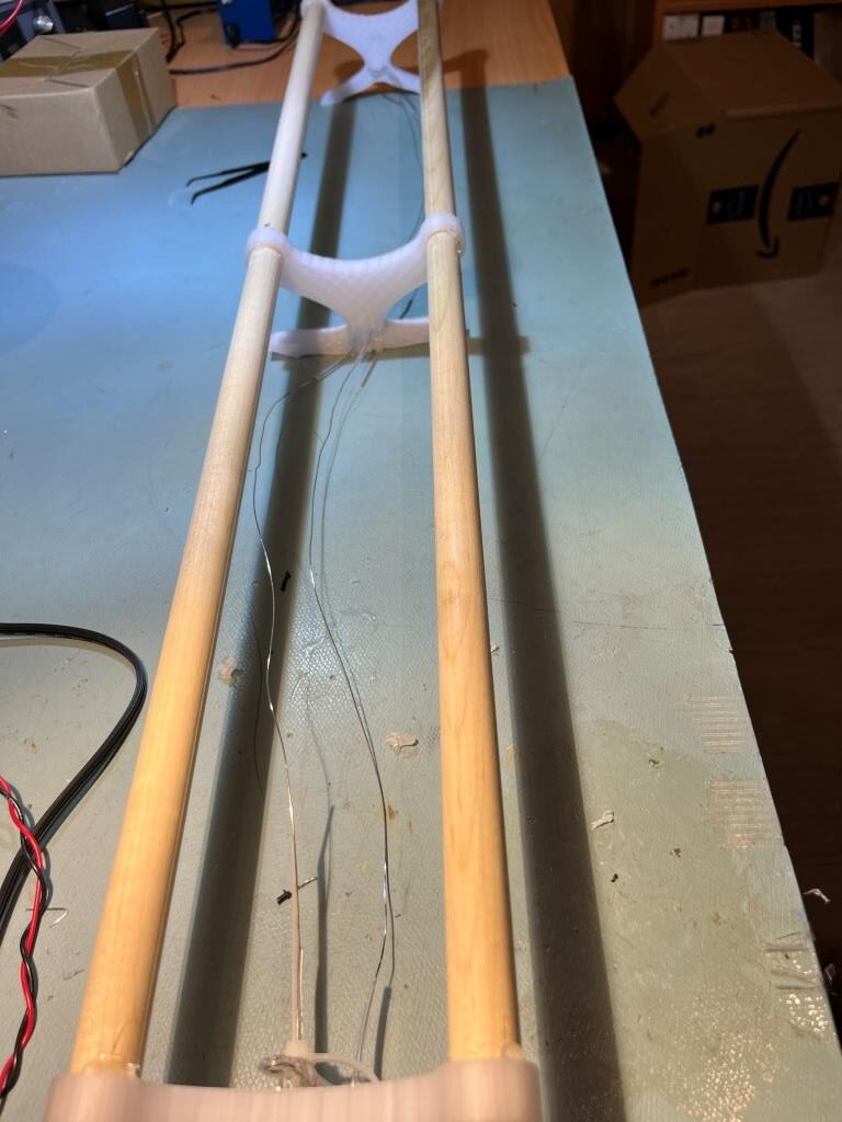
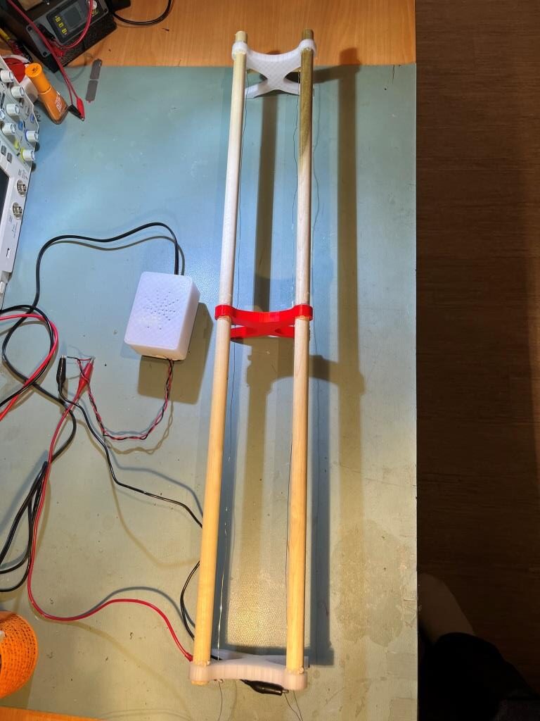
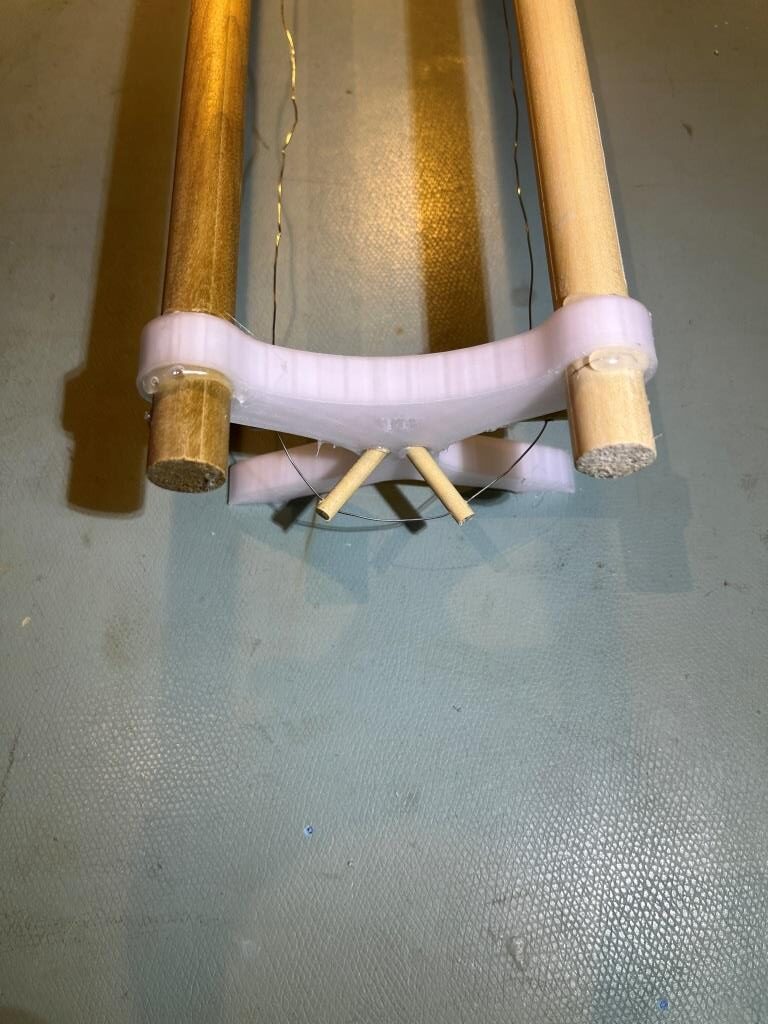
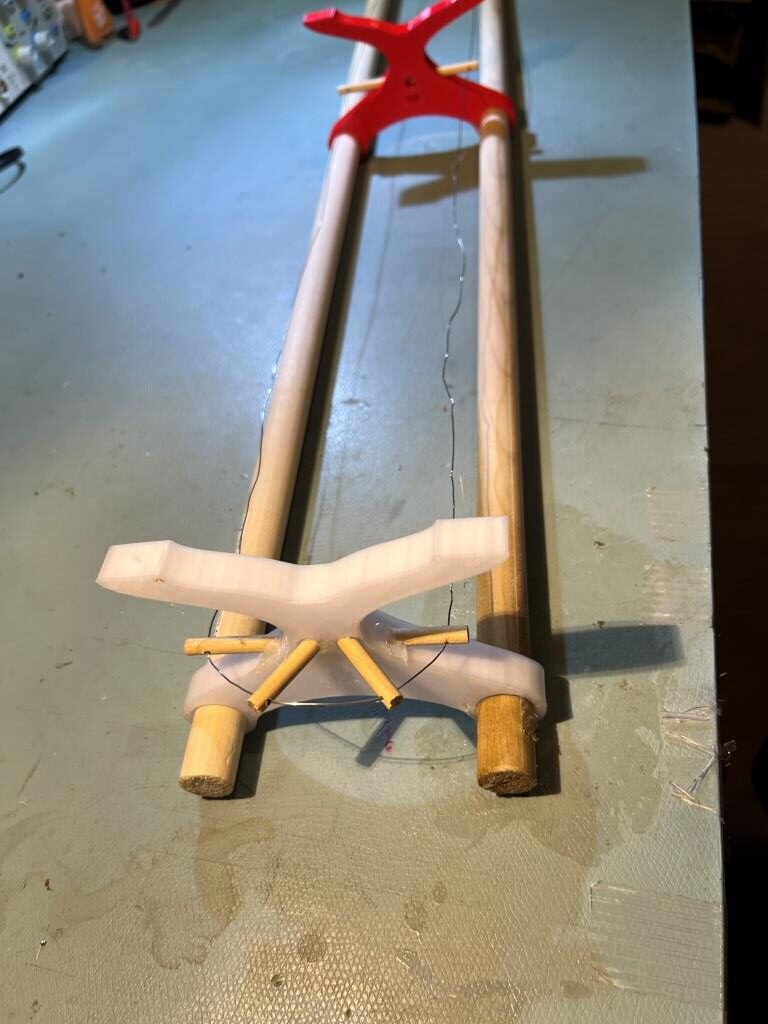
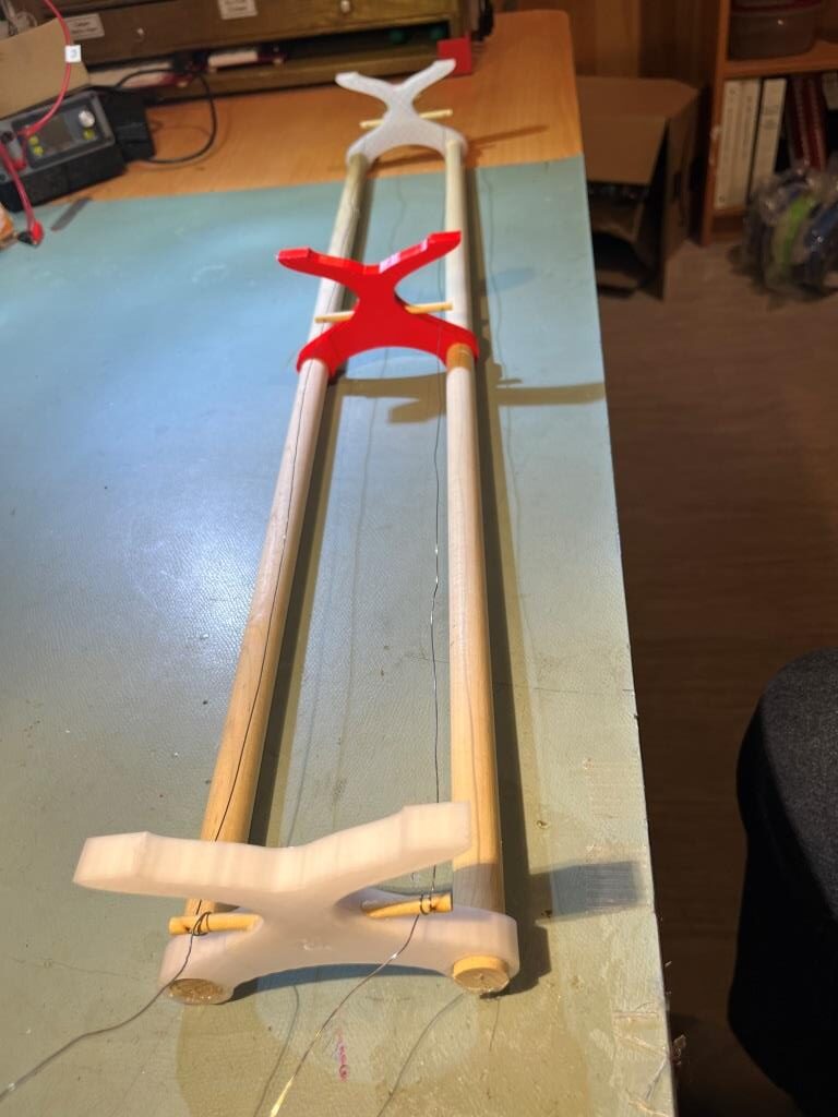
With the addition of the two end-piece rods, the nichrome wire is held well away from the printed parts. Also and the wire run can now be pulled taut and looped around the dowels on the power supply end – much nicer installation.
Here are a couple of photos showing the mostly-finished installation, minus only the cabling from the power supply to the filament reel rack and the reels themselves
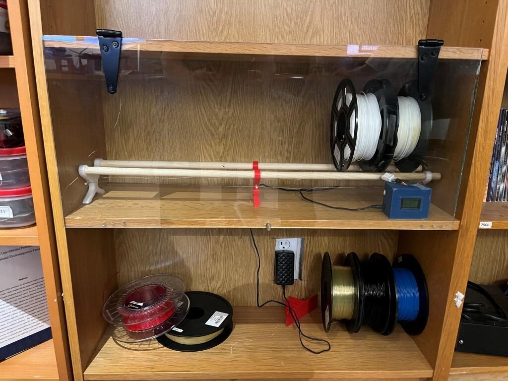
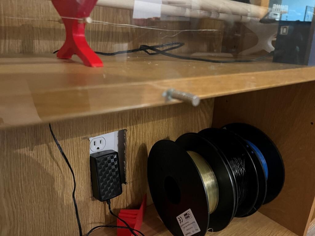
Just as an aside, I have now been using OnShape for just over one year now, and I am beginning to really like it. I am by no means an expert, and I still have to spend as much time researching a particular technique as I do implementing it, but I now firmly believe it has taken top spot in my pantheon of good, bad, and ugly 3D design packages.
Stay Tuned!
Frank