Yearly Archives: 2023

WallE3 Doesn’t Like Reflective Surfaces

Posted 08 December 2023

WallE3 went with us last month when we travelled to St. Louis for Thanksgiving with family, and I showed off his autonomous wall following skills. WallE3 actually did great for quite a while – that is until he found himself staring at the side of a floor-mounted wine cooler (wine ‘safe’?). As can be seen in the following short video, WallE3 fell in love with the cooler, and showed his love by repeatedly head-butting it – oops!

After looking at the telemetry data for the run, I saw that WallE3 was measuring much larger front distances – like several hundred centimeters – when it was only a few centimeters from the object. It appears he was backing up to a defined front distance in response to a ‘WALL_OFFSET_DISTANCE_AHEAD’ anomaly, but somehow convinced himself that instead of 20cm from the wall, he was actually more like 100cm away. Of course, since he wanted to be at 30cm (the desired wall offset distance), he drove forward to lessen the distance, thereby bonking into the wall. Then, when he hit the wall, the front LIDAR line of sight geometry changed enough to produce a true measurement of just a few centimeters, which then sent WallE3 running backwards to open up the distance. Lather, rinse, repeat. Here’s an Excel plot of a representative (but not exact – I somehow lost the actual telemetry data for this run).
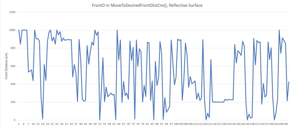
Representative reflective surface ‘headbutt’ telemetry

As can be seen from the above the measured distance oscillates between the maximum measurable distance of 1000cm to nearly zero. Here’s a photo of the experimental setup that produced the above data.
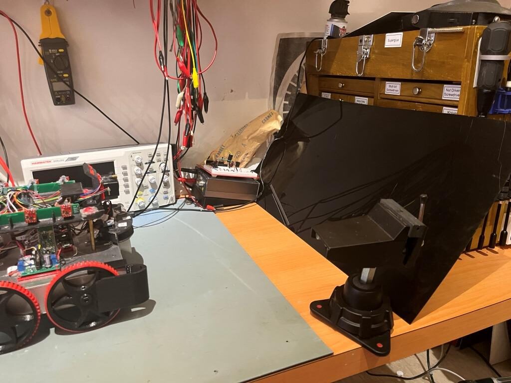
WallE3 and a reflective surface

The ‘reflective surface’ is a piece of glossy black translucent plastic, oriented at an angle to reflect WallE3’s LIDAR beam upward to the ceiling and then the reflected signal from the ceiling back to WallE3.

I’ve been thinking about this issue ever since first seeing it in St. Louis, but hadn’t come up with any firm ideas about how to solve it. I tinkered with the idea of generating two running averages of the front distance when in the ‘MoveToDesiredFrontDistCm()’ function, with the two averages separated in time by some amount. When approaching a normal non-reflective surface, the two averages would closely track each other, but when approaching a reflective surface that produced the above dramatic distance shifts, then the two averages would be dramatically different around the transitions. This could then be detected, and something done to recover. Then last night while falling asleep, I wondered whether or not the STMicro VL53LXX infra-red LIDAR sensors would have the same problem – hmm, maybe not! If that were the case, then I could probably run one in parallel with the Garmin LIDAR unit, and use it instead of the Garmin for all ‘MoveToDesiredFront/RearDistCm()’ calls.

I tried this experiment using the currently installed rear distance sensors by calling ‘MoveToDesiredRearDistCm()’ with the same reflective surface setup as before, as shown in the following photo:
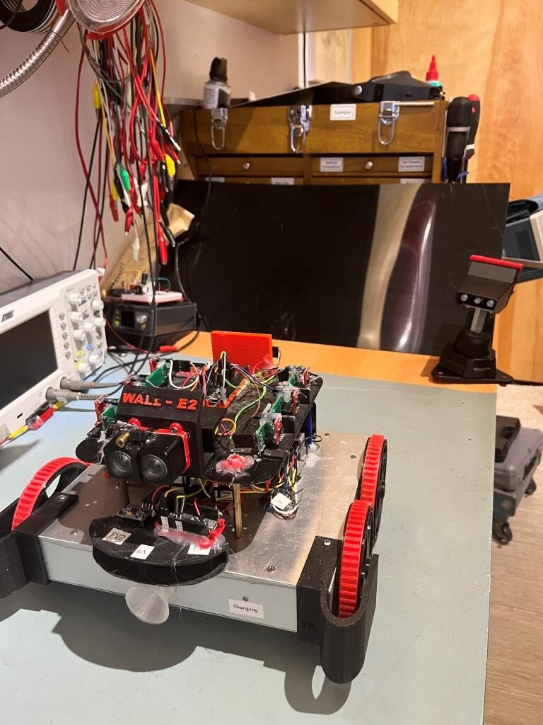
‘MoveToDesiredRearDistCm()’ setup with reflective surface

Here’s an excel plot of the rear distance run:
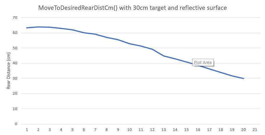
MoveToRearDistCm() with 30cm target and reflective surface

As can be seen in the above plot, the rear distance run was completely normal, so the VL53LXX infra-red LIDAR sensors don’t have the same problem – at least not with this translucent glossy plastic material.

10 December 2023 Update:

I got to thinking that maybe the reason the rear distance sensor worked so well with the shiny black material is that it could be IR transparent, meaning that while the front sensor (an LED LIDAR system) would see a ‘mirror’, the rear sensor would just see the toolbox. So, I jumped up on Amazon and got a cheap mirror square so I could answer that question. Here is a short video and Excel plot showing a ‘MoveToDesiredFrontDistCm()’ run with the new mirror square.

As can be seen from the video, WallE was perfectly happy to drive right through the mirror, but I had visions of mirror pieces all over the bench, the floor, and me, so I manually prevented that from happening. Here’s an Excel plot showing the same run:
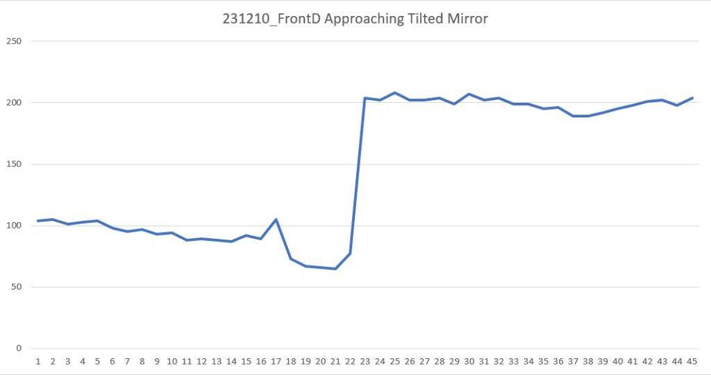
MoveToFrontDist(cm) approaching tilted mirror

As the Excel plot shows, the robot did OK for the first 20 measurements (about 1sec) but immediately thereafter started a steady 200cm, and it stayed that way until I stopped it at about 2sec

Then I tried the same experiment, but this time utilizing the STMicro VL53LXX IR LIDAR sensor on the rear of the robot, as shown in the following short video:

As the video shows, the IR LIDAR behaved pretty much the same as the LED LIDAR (no real surprise, as they are both LIDAR technology, but still a bummer!

Here’s the Excel plot for this run:
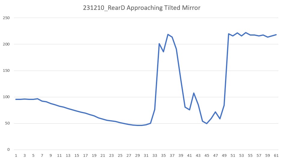
As the Excel plot shows, the distance decreased monotonically for the first 30 points (about 1.5sec) but then shot up to 200 due to the mirror. I believe the lower distances after about point 40 (2sec) were due to me interfering with the IR beam.

So, unfortunately my theory about the rear IR sensor doing better with the shiny black plastic ‘mirror’ because it appeared transparent at that wavelength seems to be bolstered, so I now think that using the VL53LXX sensor instead of the Garmin LIDAR LED sensor for ‘MoveToFrontDistCm()’ operations is NOT going to work. Back to the drawing board :(.

23 December 2023 Update:

I’ve been thinking about this problem for a while now, and have not come up with a good answer; WallE3’s perception of the world around it depends entirely on LIDAR-type distance sensors, so if those sensors produce ‘false’ distance reports due to mirror or mirror-ish surfaces, WallE3 has no way to know the ‘true’ distance – bummer!

So, what I decided to do is to simply detect the symptoms of the ‘mirrored surface’ situation, halt the robot and yell for help. The detection algorithm uses the knowledge that when the robot is moving forward toward a ‘normal’ object, the front distance should decrease monotonically with time. Similarly when the robot is moving backwards toward a ‘normal’ object, the rear distance should decrease monotonically with time. Conversely, when approaching a ‘mirror-like’ object, the measured distance tends to be unstable, with distance increasing instead of decreasing.

The detection algorithm calculates a three-point average each time through the action loop, and compares the result to the last time through the loop. If the new average is greater than the old average, a ‘mirrored surface detection’ is declared and the robot calls ‘YellForHelp()’ which stops the motors and emits an audible Morse code ‘SOS’.

Here’s the full code for ‘DoOneMoveToFrontDistCm()’ function that actually moves the robot and checks for ‘mirrored surface’ error conditions

02 January 2024 Update:

I wasn’t really happy with my previous attempt at ‘mirrored surface’ detection as it seemed pretty to produce false positives. After thinking about the problem some more, I thought I might be able to use a distance variance calculation as a more robust detection method. The idea is that a normal monotonic increase or decrease in distance measurements would have a pretty low variance, while a distance reversal would generate a much larger value.

So, I ran some simulations in Excel using a 5-point running variance calculation, and the results were encouraging. Then, with the help of my lovely lab assistant, I set up an experiment in my office sandbox to see if I could capture a representative mirrored surface ‘screwup’, as shown below:

And here is an Excel plot showing the results (both the distance and 5-pt variance vertical scales have been truncated to show the smaller scale variations)
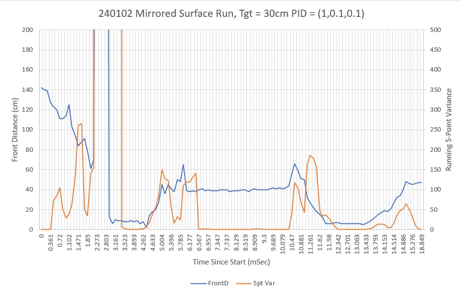
Front Distance and 5-pt Variance (truncated vertical scales for better visibility)

As can be see in the video and the Excel plot, the robot undergoes a number of distinct front/back oscillations, but then eventually settles down. It is clear from the plot that the 5-pt variance calculation is a good indicator of a ‘mirrored surface’ condition. Just looking at the plot, it appears that a variance threshold of 40-60 should provide for robust detection without much of a risk of false positives.

One other note about this experiment. To get multiple oscillations as shown in the video and plot, the mirrored surface had to be slanted slightly up toward the ceiling. If the surface was oriented vertically like a normal wall, the robot would often miss the first distance and hit the wall, but then would typically back off to the correct distance. I think this indicates that in the vertical configuration, there is enough backscatter from the floor and/or the robot itself to get a reasonable (if not entirely accurate) LIDAR distance measurement.

07 January 2024 Update:

After playing around some more with this issue, I think the above 5pt variance calculation for ‘mirrored surface’ detection will work, so I revised my current well-tested ‘CalcBruteFrontDistArrayVariance()’ function to take a integer argument denoting the number of elements to use, starting at the end (most recent data) and working backwards.

Then I ran another test in my lab, but this time on a non-mirrored surface, to verify that the 5pt variance calc would still work properly and to settle on a good threshold for ‘mirror’ detection. The Excel plot below shows the results of a run where the robot moved backwards (still using the front LIDAR sensor) to 90cm from the wall.
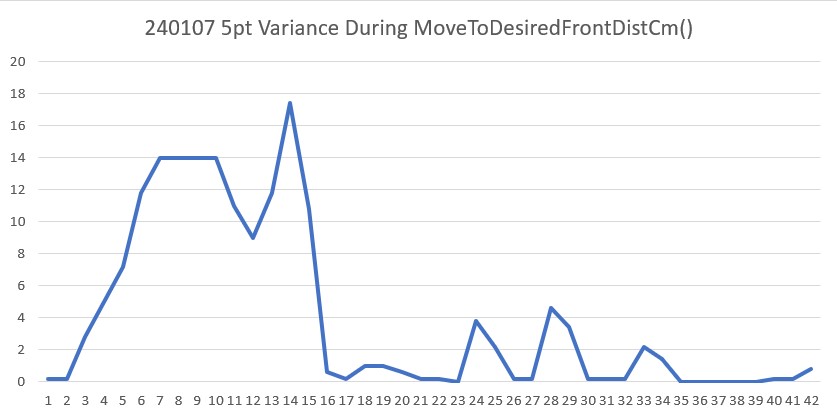
Running 5-point variance of front distances

As can be seen, the variance starts out in the 10 to 20 range during the initial ‘coarse’ distance movement, but then drops into the 0 to 5 range during the second ‘fine tuning’ movement. Comparing this to the previous ‘mirrored surface’ plot leads me to believe that a threshold of 40 would almost certainly (eventually) detect a ‘mirrored surface’ condition.

24 January 2024 Update:

I added the ‘CalcFrontNPointVar(uint16_t N)’ function to the robot code so I could obtain the front variance using just the last N front distances instead of the entire 100 point array. This turned out to work very well for detecting the ‘Mirrored Surface’ anomaly condition. Then I added ‘ANOMALY_MIRRORED_SFC’ to the list of anomaly codes, and added a ‘case’ block in ‘HandleAnomalousConditions()’ to deal with this condition. The handler function is:

At the moment, all it does is call the ‘RunToDaylightV2()’ function, which does a 360º search for the best direction in which to move next. Here’s the telemetry and a short video showing the action.

This experiment led to one of those “Well, DUH!! moments, as the robot’s preferred ‘RunToDaylight()’ heading was right back at the mirrored surface!

After recovering from my ‘face-palm’ moment, I realized I needed to modify the ‘RunToDaylight() function to take heading-start & heading-end parameters to exclude the mirrored surface sector from the ‘RunToDaylight()’ search for an appropriate recovery heading.

28 January 2024 Update:

I modified ‘RunToDaylightV2()’ to take two float parameters denoting the start and ending headings for the search. In the normal non-mirrored surface case, ‘RunToDaylightV2()’ is called with no arguments. The no-argument overload simply calls ‘RunToDaylightV2(startHdg, endHdg)’ with startHdg = endHdg. In the mirrored surface case, the two-parameter version of ‘RunToDaylightV2()’ is called from the ‘ANOMALY_MIRRORED_SFC’ case block of ‘HandleAnomalousConditions()’

Here’s a short video and the telemetry from a test run toward a mirrored surface.

Stay tuned!

Frank

PID Integral Windup Problem in MoveToDesired(Front|Back|Left|Right)Distance()

Posted 14 November 2023

After getting the charging station (re)integrated with the rest of the system, I have been working on complete travel-charge-travel charge cycles, where WallE3 travels around the house, finds and connects to the charger, disconnects, travels around the house some more, and then finds its way back to the charger – lather, rinse, repeat.

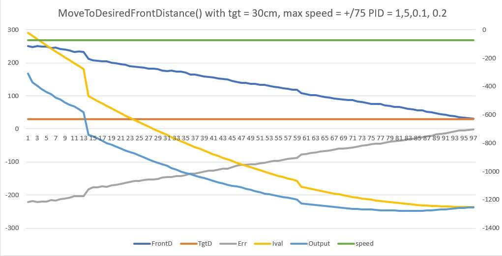
However, in the process I have run into a problem with the MoveToDesired(Front|Back|Left|Right)Distance() function. On several occasions the robot has blown right by the desired distance and run headlong (or backlong?) into a wall. Investigating has led me to realize that the cause of this problem is the infamous ‘integral windup’ characteristic inherent in insufficiently sophisticated PID algorithms. Here’s the relevant telemetry from a recent MoveToDesiredFrontDistance() run, and an Excel plot showing the ‘integral windup’ issue.

MoveToDesiredFrontDistance run showing integral windup problem

In the above Excel plot, the initial error is -221, which causes an output of ~300. The motor speed is clamped to -75, so the distance and error start slowly heading toward the target of 30cm and an error of zero. However, the integral (I) term continues to increase from near zero to well over -1000, and the output term was completely dominated by the integral value, keeping the motor speed clamped at -75 even as the measured distance approached and passed the target. In this particular case, I got lucky as the actual distance and the target distance were within the +/- 1cm termination window and the loop terminated. In other cases where the actual distance went through the termination window too rapidly, the robot would basically continued forever – or at least as long as necessary to ‘unwind’ the integral term.

So, what to do? Reading up on ‘integral windup’, I found this article from around 1990 (judging by dates on the references), and I decided to try the method described there as the ‘back-calculation and tracking’ method. The idea is that when the output gets clamped to some maximum value (+/- 75 in this application), the integral value is recomputed to a value that would produce the output that would naturally produce the clamp value. For instance for an error value of -221, the Ival is -22.1 which results in an output of -309, which gets clamped to -75. For an output of -75 with an input error of -221 we have -221 + Ival*(-221) + (-221*1.5) = -75 –> Ival = (-75 + 331.5)/-221 = -1.16. Checking, -1.16*(-221) = 256.36, 1.5*(-221) = 331.5, 256.36 – 331.5 = -75.14.

After thinking about this some more, I wondered if instead of back-calculating a new I value, maybe I could simply zero out the retained ‘last_Ival’ parameter whenever the PID output value is high enough so that it would get clamped. Assuming the same clamping value of 75 and a ‘P’ value of 1.5, this would happen any time the absolute value of the error value is greater or equal to 75/1.5 = 50.

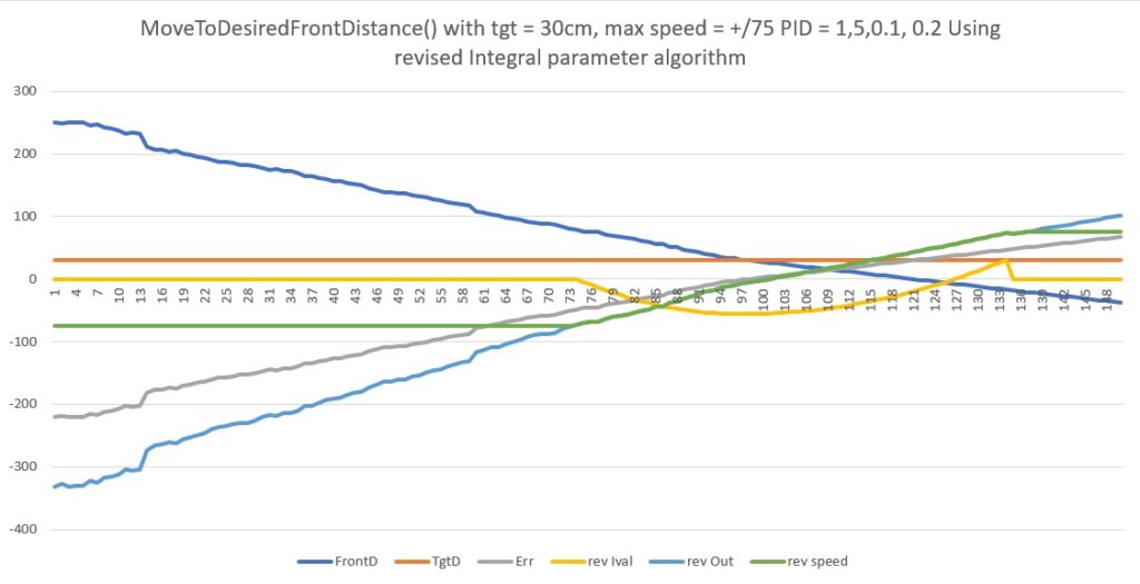
Using Excel to apply this algorithm to the telemetry above telemetry data, I get the following plot.

MoveToDesiredFrontDistance run showing integral windup problem, with modified Integral term algorithm

In the above plot, the integral term (yellow line) was modified to be exactly zero whenever the output would have been > 75 or < -75 (the motor speed clamping values), even with a zero I value. As can be seen above, it stays zero until point 75. After that it smoothly decreases to about -55.6 at point 99, and then smoothly increases to about 30.98 at point 135, at which point is gets clamped to zero again. The motor speed value (green line) stays at -75 to point 75, at which point it smoothly (and linearly it appears) increases to +75, where it is clamped again.

I believe this might just do the trick. It will certainly prevent infinite runaway if the error term goes through zero too quickly to cause the loop to exit, as the robot will stop and then back up to the target distance.

I *think* I can modify my ‘PIDCalcs()’ function, and then everything that uses it will get the benefit of the ‘non-winding integral term’ algorithm.

17 November 2023 Update:

One day to go until SpaceX makes its second attempt at getting the world’s largest rocket into space – yeah!

To work the ‘integral term windup’ issue, I ported the FrontBackMotionTest code from an earlier program into the WallE3_Quicksort_V4 project so I could iterate easier, and got that running. As a baseline, here is the telemetry and a short video from the first run:

As can be seen in the above telemetry, the ‘Ival’ column shows that the integral term increases monotonically from -19.7 to -998.4, forcing the speed to its maximum value (75) for the entire run. This causes the robot to badly overshoot the target distance, which is why I decided to have the robot perform the ‘second time through’ action shown in the telemetry and video.

I added the following code to MoveToDesiredFrontDistCm() to zero out the ‘lastIval’ value if the error term * Kp > MOTOR_SPEED_QTR

Here is the telemetry and the video from the run with the above change

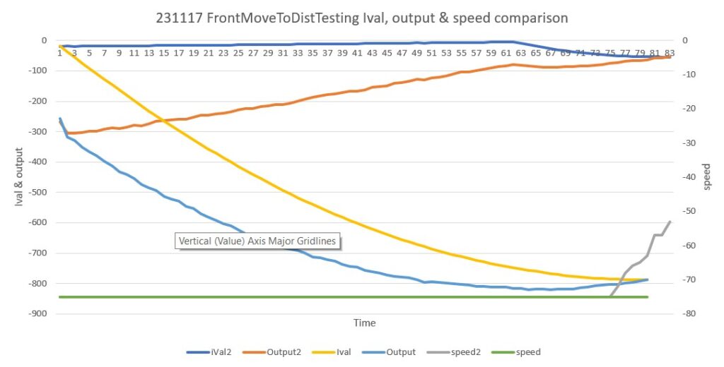
As can be seen from the above, this change did not affect the robot’s behavior significantly – it still badly overshot the target distance and the ‘second try’ was still required to bring the robot back to nearer the target. However, from inspection of the ‘Ival’ values it is clear that the added code is doing its job of zeroing out the ‘lastIval’ term when [error_term]*Kp > Max speed. Here’s an Excel plot showing the ‘Ival’ and ‘output’ terms from both the above runs.

comparing Ival, output, speed vals before and after Ival clamp mod

In the above plot, the ‘after Ival term stays at a very low (negative) value for almost the entire run, due to the new clamping code. Consequently the ‘after’ output term decreases linearly with the decreasing error term until the resultant ‘after’ speed command comes off the -75 ‘stop’ as shown by the gray line in the above plot.

Unfortunately, the speed reduction from ‘lastIval’ clamping isn’t enough to prevent the robot from overshooting almost as much as it did before. This indicates (at least to me) that at least the Kp value is way too high. Just as a thought, the Kp value should be just high enough so that if the distance error is, say, 100cm, then the output would just clamp at MOTOR_SPEED_LOW –> 75. So, 100*Kp = 75 –> Kp = 0.75, or about half its current value.

It turned out that I not only needed to cut the Kp value in half, but the Ki value as well, so now PID = (0.75, 0.05, 0.2). Here’s the telemetry and video from a run using these values:

I wasn’t able to eliminate the ‘second try’ requirement, although I was able to reduce the overshoot to about half its previous value.

One possible fly in the ointment is the rapid drop of the front variance value during the second run through MoveToDesiredFrontDistCm(); this *should* have triggered an exit from the function with anomaly code = ANOMALY_STUCK_AHEAD, but didn’t – and I don’t know why.

Too tired to go down this rabbit hole tonight – try again tomorrow while waiting for Space X to make history with its second StarShip test flight!

18 November 2023 Update:

Wow! Wow! Wow! I had the pleasure of watching SpaceX’s literally historic second Starship test launch this morning, and I’m still psyched! I have now had the pleasure of watching both a Saturn V launch as part of the Apollo moon landing program and now the Starship and booster launch as part of (I hope) the Mars landing program.

OK, back to robots. Last night while drifting off to sleep, it occurred to me that the ANOMALY_STUCK_AHEAD alert is conditioned on the current motor configuration as well as the front variance value. Here is the actual code that determines this:

So in this case, the motors were running in reverse, so neither of the motor conditions were TRUE, and therefore IsStuckAhead() returned FALSE. Mystery solved!

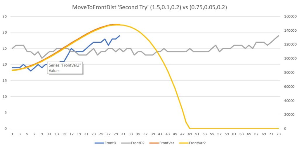
At this point I think I’ve done as much as I can with the FrontBackMotionTest program. I will modify the other ‘MoveTo’ functions to clamp the Ival term as described above. However, it is also clear that the ‘second try’ part of the ‘MoveTo’ functions cannot be eliminated without having to accept significant target distance overshoot, and that the original PID values (1.5, 0.1, 0.2) actually work better than (0.75, 0.05, 0.2), as the lower PI values cause the second try operation to take significantly longer. Here’s an Excel plot comparing just the ‘second try’ results for both:

‘Second try’ results for (0.75,0.1,0.2) and (0.75, 0.05, 0.2)

In the above plot, the ‘2’ results are for (0.75, 0.05, 0.2). As can be seen, the ‘2’ configuration takes over twice as long to complete as the ‘normal’ (1.5, 0.1, 0.2) run, and the issue with the front variance value going to zero doesn’t exist for the ‘normal’ run.

This makes it clear that while clamping the Ival does help significantly, the change in PID values does not.

18 November 2023 8:43PM EST Update:

While cleaning up the code, I noticed I had missed one spot where the global OffsetDistKp value should have been replaced by ‘Kp’, the local value, and unfortunately it was in the section that determined whether or not the Ival value would be clamped, as shown below:

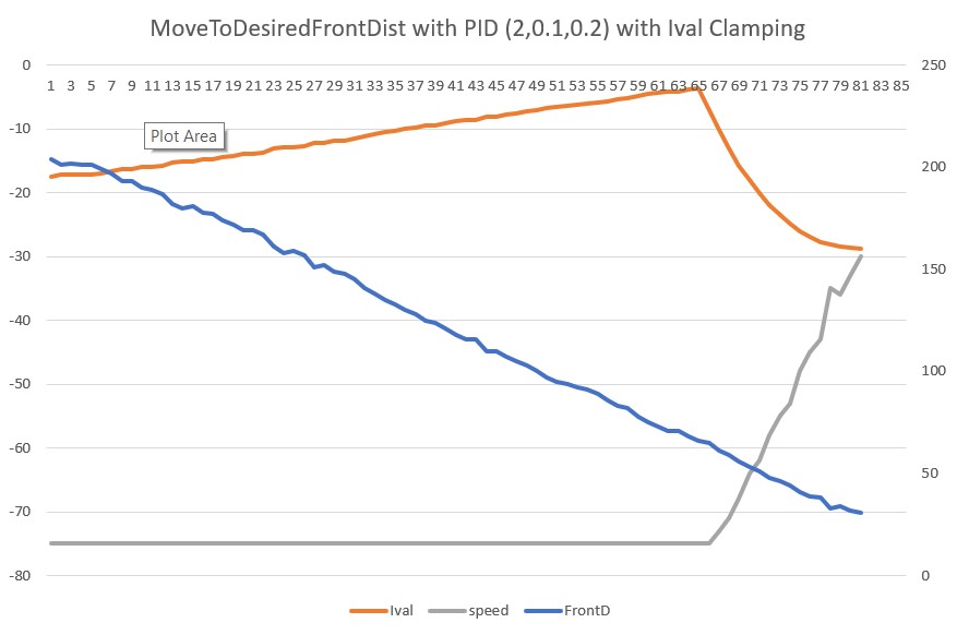
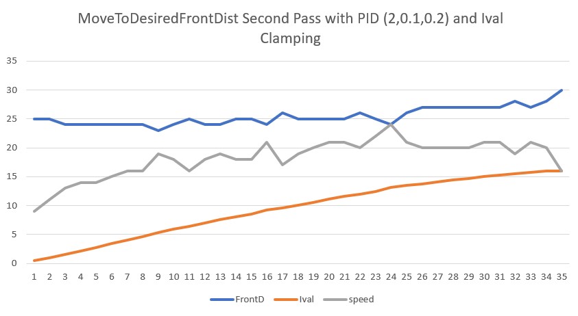
This had the effect of skewing the point at which the Ival stopped being clamped, so the previous results are a bit suspect. I ran a few more tests, and discovered the function actually performed better with a higher Kp value than the original 1.5. The reason for this is that a higher Kp value moves the point at which Ival can start accumulating later in the run (closer to the target distance thus less error), and so more quickly reduces motor speed. In addition, the Ival clamping action has no effect on the second pass through the function as the motor speed values never approach the max speed, so this part operates as designed as well. Here’s a run showing the result of using a PID of (2.0, 0.1, 0.2):

As the data shows, the overshoot is only 6cm (as opposed to the 18cm overshoot without the Ival clamp), and the recovery pass completes in about 2 sec instead of over 5. Here are Excel plots showing the primary and secondary passes.

Second pass correction with PID (2.0,0.1,0.2). Time scale is 20 units/sec, so total time ~ 1.5sec

So, it looks like I want to change the global OffsetKp value from 1.5 to 2.0, leaving Ki & Kd unchanged.

19 November 2023 Update:

Looking back at the results from the above tests, I realized that the second call to MoveToDesiredFrontDistCm(Offset, Kp, Ki, Kd) (the ‘second time though’ step) isn’t actually in the MoveToDesiredFrontDistCm() function – it is part of the test harness. So, I think I need to incorporate the second pass directly into the function so it will get performed everywhere MoveToDesiredFrontDistCm() is called. I wonder if I can do this recursively, by calling MoveToDesiredFrontDistCm() from inside MoveToDesiredFrontDistCm()?

So, I moved the ‘Second Time Through’ code from the test harness into MoveToDesiredFrontDistCm(), as shown below:

Here’s the telemetry from the run with recursive MoveToDesiredFrontDistCm() calls:

The first run through MoveToDesiredFrontDistCm() occurs normally, with the exit at the 30cm target distance as expected, and then the expected overshoot to 25cm. Then the second call to MoveToDesiredFrontDistCm() starts at 24cm and gets to 29cm in approximately 1.5sec, followed by two more 10-item distance displays. I guess the first distance display is from the one inside the MoveToDesiredFrontDistCm() call, and the second one is the one from the test harness. I need the delay caused by the 10-distance display, but I can probably replace it with just a 1-sec delay.

Here’s another run with the loop replaced by a 1-sec delay:

From the above, it looks like the function is doing what it should. It keeps iterating until the distance measured after a 1-sec delay fits within the +/- 1cm window.

MoveToDesiredRearDistCm():

Now that MoveToDesiredFrontDistCm() is working, I started on MoveToDesiredRearDistCm(). I started by copying MoveToDesiredFrontDistCm() and changing all relevant occurrences of ‘Front’ to ‘Rear’. This was about 99% of the required effort. However, there were two issues that surfaced during the port. The first was that the test program needed the ability to pass the PID values into the function, but all the mainline code uses just a single parameter (the desired offset). As a temporary fix I created a four-parameter version of the function with all the code, and had the single parameter version pass the global PID values to the four-parameter on. However a much better solution was to remove the single parameter version of MoveToDesiredFrontDistCm() entirely, and instead declare the four-parameter version with three default values right after the definition, as shown here:

The second issue was the sign of the speed variable in the RunBothMotorsBidirectional() function. For MoveToDesiredFrontDistCm() the parameters to this function had to both be negative, as in RunBothMotorsBidirectional(-speed, -speed), but in the MoveToDesiredRearDistCm() they have to be positive as in RunBothMotorsBidirectional(speed, speed). Once this was accomplished, the MoveToDesiredRearDistCm() operation was successful.

MoveToDesiredLeft/RightDistCm():

I started on these two functions, but soon realized that these two functions aren’t called anymore. They were originally used as part of wall offset capture operations, but were abandoned in favor of an algorithm that uses a perpendicular approach. Soooo, I will just remove these two functions entirely and call it good!

Stay tuned,

Frank

Charging Station Connect/Disconnect Cycle

Posted 11 November 2023

After getting the wide-body IR homing PID values defined properly, the next challenge was to actually get the robot to connect to the charging station, and after getting charged, to disconnect from it successfully. After the usual number of errors and goofs, I believe I have it working now. Here is a short video and the telemetry for a complete walltracking – IR home to charging station – disconnect from charging station – back to walltracking cycle

And here is the telemetry for the run:

Wide Body Robot Charging Station Homing PID Tuning

Posted 30 October 2023

Almost exactly two years ago I redid the robot form factor for better turning performance, as described in this post. Now, two years later when integrating the new ‘wide body’ robot with the charging station, I belatedly discovered that the PID values optimized for the old ‘narrow body’ robot don’t do so well anymore. Here’s a short video and telemetry showing the wide body robot homing with the old narrow body PID values.

I strongly suspect that the new form factor will require a significantly different set of PID values. Here

04 November 2023 Update:

Well, I went down a bit of a rabbit-hole on this one, but I think I have successfully found my way back to the real world. It’s been a while since I’ve had to do any PID tuning, so my skills (and code) have atrophied significantly. Fortunately, my former self left me some rudimentary clues, so I didn’t have to recreate everything from scratch.

In previous tuning sessions, I had constructed a test harness that accepted PID values on the command line of the OTA serial connection to the robot, allowing rapid parameter optimization. Unfortunately, I didn’t document this in my previous posts (what was I thinking!), so it took me a while to find some previous programs that contained the desired test harness code. After porting the test harness code to my current WallE3_Quicksort_V4 program and modifying it a bit for more testing convenience, I am documenting it here so a future me will have a better chance of avoiding unnecessary work.

PID Tuning Test Harness:

The idea behind the PID tuning test harness is to allow the user to input PID (and other) parameters on the command line and have the robot execute the desired action – in this case homing to the charging station – without having to go through the entire program structure. The test harness code is placed at the end of the setup() routine and doesn’t exit but returns to the point where a new set of parameters can be provided. This allows for rapid iteration over the PID parameter space. Here is the code as it appears in WallE3_Quicksort_V4.ino

Note that the ‘CheckForUserInput()’ function calls in the above assume a boolean return value; this change was necessary to allow the test harness to be run multiple times without having to reboot the robot code. This also required adding a new function key (*) to the list of keys handled by CheckForUserInput(). Here are the new versions of the two flavors of CheckForUserInput():

Now that I’ve gotten the test harness set up, I can actually start re-tuning the charge station homing PID values for the new wide-body robot – yay! Here’s a short video and telemetry from the first run with PID(50,0,0).

Here’s another run, this time with PID = (100,0,0)

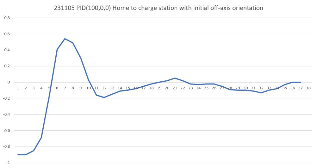
Here’s the PID = (100,0,0) run again, but starting with an initial orientation offset:

And here is an Excel plot showing the steering value vs time:

This is a pretty nice result, and I’m tempted to leave it just like this.

28 October 2023 ‘Field Test’

Posted 28 October 2023

Field test starting in bedroom hallway, just before MBR door. I have elected to start here, as WallE3 has been consistently making it this far with no problems whatsoever. Everything wen OK except for a couple of strange occurrences where it appeared that WallE3 was simply going straight without tracking anything. One of these occurrences was right at the end of the run. Here’s the video of the run:

And here’s the telemetry:

The strange behavior occurs just after WallE3 changed from the left to right-hand wall when it hits the open doorway of the larger guest bedroom, and then makes the hard right-hand turn to follow the near wall when it exits the hallway into the dining room area.

From the video, this occurs at approximately 203 sec, so I have excerpted the telemetry starting at the point where the robot transitions from the left to right wall.

At 215.3 sec WallE3 experiences another EXCESS_STEER_VAL anomaly (as the robot exits the hallway into the dining room area). WallE3 makes a slight right turn, moves forward a bit, and stops; this is the normal ‘move ahead one skosh’ after an EXCESS_STEER_VAL anomaly detection.

Then at 216.6 sec with gl_Left/RightCenterCm = 219.7/77.2, Left/RightSteerVal = 1.00/-1.00 it makes another right turn to, presumably, follow the right-hand wall, but it doesn’t try to capture the 30 cm offset and track – it just goes straight, eventually running into the wall on the far side of the open doorway into the kitchen area bathroom. From the telemetry it looks like WallE3 called ‘MoveToDesiredFrontDistCm() with a target distance of 30 cm as part of ‘CaptureWallOffset()’ but started the process almost parallel to the wall rather than perpendicular.

Matching the code up with the telemetry and the video, it becomes apparent that ‘HandleExcessSteervalCase(RIGHT)’ is called by HandleAnomalousConditions(RIGHT) as soon as the EXCESS_STEER_VAL anomaly is detected.

The first thing that HandleExcessSteervalCase() does is move forward for 500 mSec – the ‘skosh’ intended to clear the point where the anomaly occurred to obtain valid distance measurements. In this case, however, the video shows that the ‘forward’ direction was slanted off to the right instead of straight ahead, which meant that instead of detecting an ‘open corner’ condition with no trackable wall in range, the robot saw a trackable wall to the right at 77.2 cm, as the following telemetry line shows:

216672: gl_Left/RightCenterCm = 219.7/77.2, Left/RightSteerVal = 1.00/-1.00 

So, instead of the ‘open corner’ block in HandleExcessSteervalCase() executing, the ‘else if (trkcase == TRACKING_RIGHT)’ block was run , as shown below:

Since HandleExcessSteervalCase was called with TRACKING_RIGHT, and because gl_RightCenterCm = 77.2 was less than MAX_TRACKING_DISTANCE_CM (100 cm), ‘TrackRightWallOffset(WALL_OFFSET_TRACK_Kp, WALL_OFFSET_TRACK_Ki, WALL_OFFSET_TRACK_Kd, WALL_OFFSET_TGTDIST_CM)’ was called without running ‘ChooseBetterTrackingSide()’.

In TrackRightWallOffset(), CaptureWallOffset(TRACKING_RIGHT, 77.2) was called because the starting offset was too high for immediate tracking. In CaptureWallOffset(), a 90º CW turn was performed to (supposedly) point WallE3 directly at the wall to be tracked, and then ‘MoveToDesiredFrontDistCm(tgt_offset_cm)’ was called to capture the wall offset of 30 cm.

Unfortunately, the 90º CW turn step assumes the robot is already oriented parallel to the wall to be tracked, but because the actual physical configuration at this point was an open corner instead of an open doorway, WallE3 wasn’t at all parallel to the wall. So, the turn just oriented the robot to about 40-45º to the wall rather than 90º. The next step in the offset capture routine is to call MoveToDesiredFrontDistCm() to move the robot to the desired offset distance (in this case, 30 cm). But the front distance measurement never got down to 30 cm, as the robot wound up running along the baseboard, parallel to the wall. This would have continued indefinitely except WallE3 ran into the far edge of the doorway into the kitchen area bathroom.

So, everything worked just like it was supposed to, except that when the robot exited the bedroom hallway it was turned just enough so that it saw what looked like a trackable wall to the right, instead of gl_LeftCenterCm & gl_RightCenterCm > MAX_TRACKING_DIST_CM, so the open corner case wasn’t executed.

To fix this problem (and hopefully not create other ones) I added the condition that to bypass the ‘open corner’ case, the absolute value of the ‘trackable side’ steering value must be less than 1/2 the max steerval of +/- 1.

Well, that didn’t work as well as I thought. I made another field run, this time starting just before the end of the bedroom hallway where it opens into the dining area. What should have happened is the robot should have detected the ‘open corner’ configuration, made a 90º CW turn and carried on tracking the right-hand wall. What actually happened wasn’t that. Here’s a short video showing the action, along with the telemetry from the run

So, it appears the same sort of thing happened again, only this time it was the left-side distance that was less than MAX_TRACKING_DIST_CM. Since both steervals were +/- 1 this should have caused the ‘open corner’ block to execute.

Fixed (again!). Running another test.

ALRIGHT!! This time things worked just like they are supposed to! Here’s a short video showing the action, and the telemetry from the run.

As can be seen from the video and telemetry, the ‘open corner’ configuration was properly detected even with gl_Left/RightCenterCm = 84.1/235.6, Left/RightSteerVal = 1.00/1.00 (left side within MAX_TRACKING_DIST_CM but abs(left steerval) > MAX_STEERVAL ). Yay!!

Stay Tuned,

Frank

The WALL_OFFSET_DIST_AHEAD Anomaly

Posted 21 October 2023,

The WALL_OFFSET_DIST_AHEAD anomaly is triggered when WallE3 is about to run head-on into an upcoming wall. The idea behind handling this anomaly is to allow WallE3 to navigate around internal corners. Up until a few days ago, WALL_OFFSET_DIST_AHEAD anomaly just called ‘BackupAndTurn90Deg(bool bIsCCW)’. This function backed the robot up to achieve the desired wall offset, turned 90º in the direction away from the last tracked wall to parallel the upcoming wall and then exited, whereupon loop() was re-entered from the top and a new tracking assessment was made.

However, this treatment failed spectacularly in the guest bedroom, as the ‘new’ wall was too short to track properly. This problem led to the development of the ‘RunToDaylight’ algorithm to allow WallE3 to find the best direction in which to travel. I now have RunToDaylightV2() working very nicely, but now I have the opposite problem; now RunToDaylightV2() is more likely than not to simply turn WallE3 180º and go back the way he came – perfectly legitimate from RunToDaylight’s point of view, but boring and too simplistic.

So, how to mix the two approaches (BackupAndTurn90Deg & RunToDaylight) so that RunToDaylight is used in tight corners, but BackupAndTurn90Deg is used for ‘normal’ wall configurations where there is ample (or at least reasonable) room for travel on the perpendicular wall.

I’m going to try combining the two options. The idea is that BackupAndTurn90Deg would be the default response to a WALL_OFFSET_DIST_AHEAD anomaly, but if the available front distance after the 90º turn is less than something like 2 x WALL_OFFSET_DIST_AHEAD (currently set at 30cm), then the RunToDaylight will be called to find a better direction in which to move.

This turned out to be pretty easy. The changes necessary to the WALL_OFFSET_DIST_AHEAD anomaly case in HandleAnomalousConditions is shown below:

The following short video and telemetry shows the action when WallE3 encounters a corner with not enough room to track the next wall in the internal corner.

And the following video and telemetry shows the action when WallE3 does have room enough to follow the internal corner wall. Note that in these two conditions, the code was not changed – the only thing that changed between the two runs is the ‘third wall’ was moved away from the first one to give WallE3 sufficient room to follow the internal corner wall.

So it seems this problem is pretty much solved – YAY!!

Stay Tuned,

Frank

Using QuickSort on Multiple Associated Arrays

Posted 06 October 2023,

At the very end of the 04 October 2023 Update to the “The Guest Bedroom Problem” post , I made the following statement:

Also, I need to figure out how to sort through the 360º search results. I would like to wind up with an array of steervals sorted in decreasing magnitude order, with a companion array of headings so Hdg[i] <–> Steerval[i]. Not sure how to do this yet, but it sounds promising!

After some research on array sorts in C++ I came across this post with a nice example of a quick sort program, which I shamelessly copied. After some fumbling around (including writing my own ‘swap’ routine to allow future porting to Arduino code) I got it to work in my Visual Studio 2022 Community Edition setup with a single int[] array as shown in the following image:

Now the challenge was to extend this algorithm to sort multiple same-sized companion arrays. Looking at the QuickSort code, it appeared all I had to do was duplicate the ‘swap’ operation on all the companion arrays using the same swap indices determined for the ‘master’ array. One additional fly in the ointment was the requirement to handle both int[] and float[] arrays.

First I modified my ‘swap’ routine to be a generic template function as shown below:

Then I renamed the ‘arr’ array from the example to ‘FrontD’ and defined a second ‘Hdg[]’ array of float values with the same length as the original example array as shown below:

Then, for each occurrence of a call to ‘mySwap’ for the ‘FrontD’ array, I added a second call for the ‘Hdg’ array as shown below:

When I ran this code, it *almost* worked right off the bat. Unfortunately the ‘Hdg’ slave array wound up being sorted slightly differently than the ‘FrontD’ master array. After closely examining the code, I finally found the problem. In one place the original programmer used the indexing syntax ‘[i++]’ and ‘[i–]’ as input to the ‘mySwap’ function. This worked fine for the single master array, but failed with the second array because on the second call to ‘mySwap’ the indices had been changed – oops! Here is the original and revised syntax:

Now both calls to mySwap() use the same index values, and life is good. Here’s a debug printout from VS2022 showing a successful program run with a master (int Frontd[]) array and one slave (float Hdg[]) array:

And here is the complete code that produced the above output:

09 October 2023 Update:

After convincing myself that this scheme for synchronizing the sorting of ‘master’ and ‘slave’ arrays, I decided to port the capability into my robot code. I created a new WallE3 program called ‘WallE3_Quicksort_V3’ as a copy of ‘WallE3_Complete_V5’, and then added the ‘quickSort’, ‘partition’, and ‘mySwap’ functions from ‘Quicksort_V3’.

Then I set up a test block in setup() as shown below:

With this setup I got the following output:

In this test, the FrontD[] is the ‘master’ and the ‘Hdg[] is the ‘slave’, and the algorithm is set up to sort the array in increasing order.As can be seen from the above output, the FrontD[] array after Quicksort is indeed sorted from smallest to largest value, and the Hdg[] array elements after Quicksort are ordered in such a way as to correspond to their original relationship to FrontD[].

In my application I want to sort the master array in descending order rather than ascending, so after some googling I found that making the following change:

causes the sort to run in the other direction, giving the following output:

As desired, the ‘FrontD’ master array is sorted in descending order, and the ‘Hdg’ slave array elements are still synchronized with their original FrontD companion elements.

So I changed the test to use real data using the initialization code below:

and got the following output:

Gee, that went well — The FrontD distance array isn’t ordered at all – yuk!

OK, so back to basic troubleshooting. The first thing I did was to replace the FrontD[6] test array in my QuickSortV3 C++ program with the FrontD[36] array of actual front distance values (edited in Notepad++ to be a single line of comma-separated values) to see if I could establish a working baseline – an absolute necessity for efficient troubleshooting.

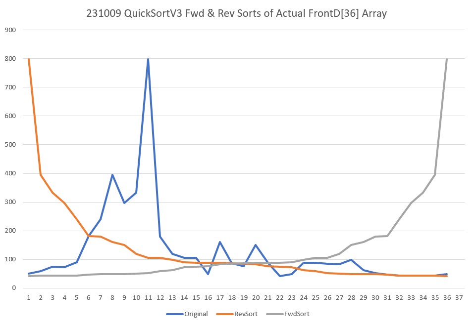
I had to edit the QuickSortV3 program to remove the references to the second Hdg[](slave) array, as I didn’t want to complicate things, but after I did this, the program sorted FrontD[36] properly in both the forward and reverse direction. To get the reverse sort, I had to flip ‘<=’ to ‘>’ in two places, and ‘>’ to ‘<=’ in one place, as shown below:

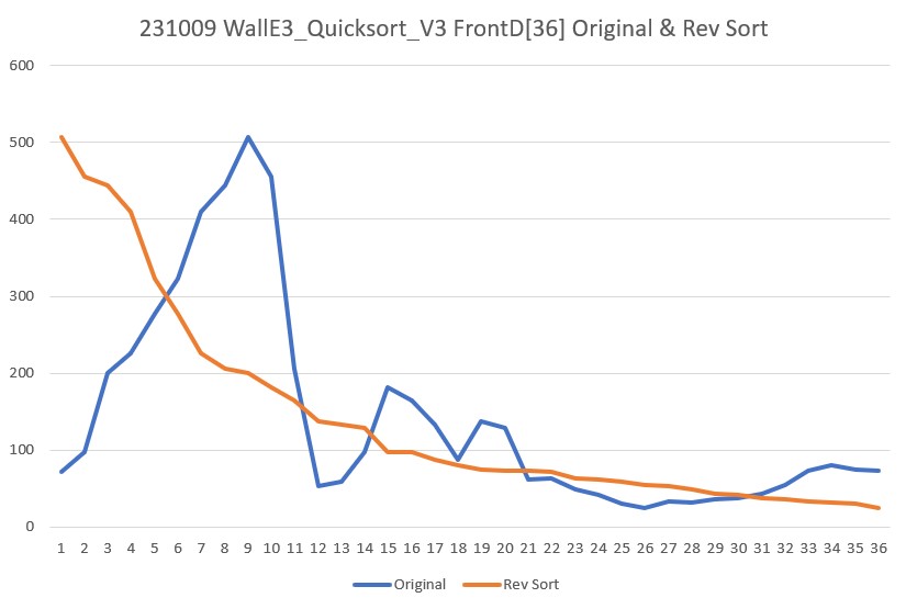
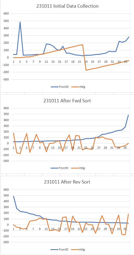
The following Excel plot shows the result for both the forward and reverse sorts

Now that I have a working baseline with my QuickSortV3 C++ program, it became easy to see the problem with my WallE3_Quicksort_V3 Arduino program; there are three places that need to be changed for reverse sorts, and I only changed one – ooops! After fixing these problems, I got the following output:

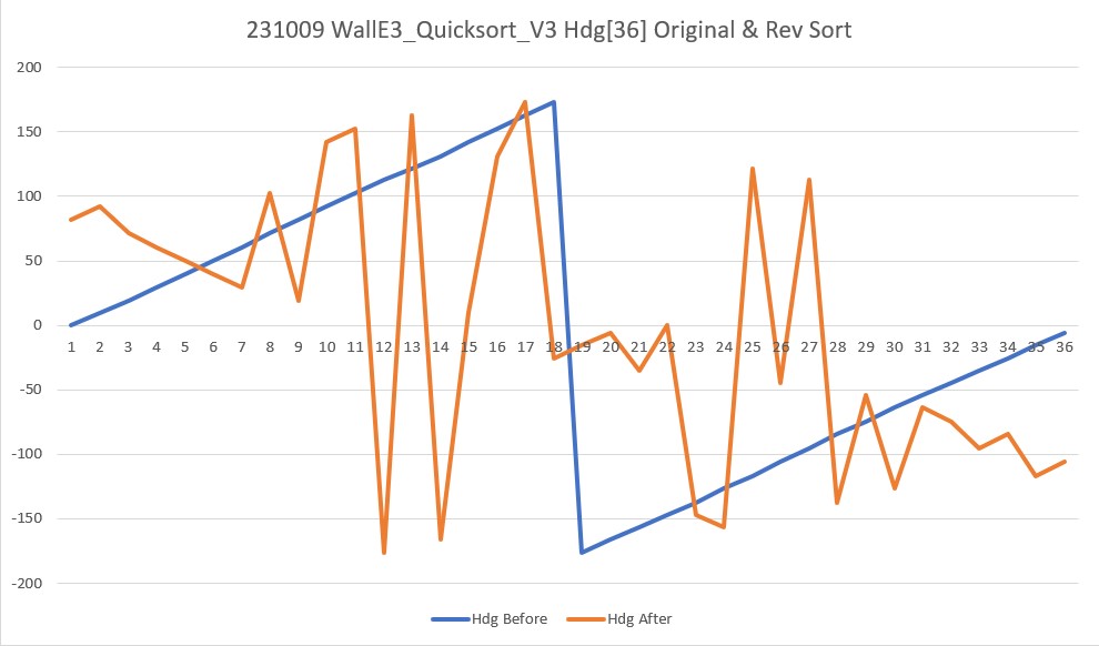
And now, the slave sort seems to be working as well, as shown by the following Excel plot:

The above plot looks very confusing at first, but it seems to be accurate; the ‘before’ picture is straightforward – the robot rotated in 10º steps, so the smooth blue line is expected. The ‘after’ plot looks crazy, but remember it is synchronized with the reverse sorted front distance array, so there is no organizing principal. The relationship of heading values with front distance values after the reverse sort is easier to see with the text output from the program, shown below:

For instance, the largest front distance shown is 507cm (row 9 in the original listing). In the unsorted data, the heading associated with 507cm is 82.1º. In the reverse sorted listing, 507cm is of course on the first row, and so is 82.1º. The lowest front distance (last row of the reverse sorted list) is 24cm, and the heading on the same line is -106.1º. Looking through the original (unsorted) list, 24cm is found on line 26, and the heading on that line is -106.1º as expected.

At this point, it is clear that my plan to have WallE3 turn a full circle while recording front distances and associated headings, then reverse sort the distance data array as the ‘master’ array while maintaining each distance value’s associated heading (the ‘slave’ array) is going to work. Then I should be able to easily find the heading associated with the median front distance of the first(only) group of front distances greater than some threshold – say 1.5m. Looking at the reverse-sorted front distance data above, I see there are about 10 distance measurements above 1.5m as shown below:

The median heading value for this group of 11 distances is 71.4º, which is associated with the front distance value of 444cm.

11 October 2023 Update:

After figuring out how to change my quickSort() function from a forward (increasing values) to a reverse (decreasing values) sort, I decided that I should make it capable of performing either sort (fwd or rev), by adding a boolean parameter to the function signature. I started by going back to my C++ program and making the mods there, and I was able to make it work fairly quickly, as the following output shows:

Then I ported the changes to my Arduino program and got the same results, as shown in the following output:

And here is the test code that produced the above output:

13 October 2023 Update:

After getting this to work in my C++ project, I ported it over to WallE3_QuickSort_V3 and got it working there. Thinking about the overall ‘Guest Bedroom Problem’, it is clear to me that I will need six synchronized arrays – FrontD, Hdg, L/R Dist, L/R Steer. At first I thought I could do this with five calls to ‘QuickSort() – one each for (FrontD, Hdg) and then one each for the remaining four, each using FrontD as the ‘master’ array. However, when I tried this, it failed miserably – only the first sort (FrontD, Hdg) worked, and the remaining four calls did nothing. After thinking about this for a while, I eventually figured out that the first call – (FrontD, Hdg) worked because each time two FrontD array items got swapped in mySwap(), the Hdg array got swapped in the same way – preserving synchrony. However, when the sorted FrontD array was used in the second and subsequent calls, mySwap() never gets called because all FrontD items are already in order. This meant that the second and subsequent ‘slave’ arrays stayed in their original unsorted state – oops!

So the answer to this problem is either keep replacing the ‘master’ parameter to QuickSort() with the unsorted version of FontD[] so that it will get sorted again (causing the required mySwap() calls to the ‘slave’ array, or modify QuickSort to take all five ‘slave’ arrays as parameters. Either way is a real PITA, but I think the ‘all at once’ strategy is more straightforward.

After implementing the ‘all at once’ strategy, I got the following output from my test program:

It appears that both the FWD & REV sorts succeeded (at least with respect to the front distance values). Spot checking the other arrays, we see for front distance values of 23 & 449:

So it is clear that all six arrays are synchronized through both FWD & REV sorts – Yay!

Looking at the reverse sorted and synched data for FrontD values above 1.5m we see a number options for travel directions, as detailed by the following lines from the reverse sort output:

The first four lines above are all ‘left-side’ tracking options. The fifth line above (at FrontD = 240) could actually utilize either the left or right walls for tracking, and the last two are ‘right-side’ options.

The option with the largest ‘head room’ (515cm) is shown in the first line above; on a relative heading of 82.0º, there is 515cm of travel distance available, and the robot is 30.2cm away from the left wall and is oriented almost parallel to it (left steerval is -0.2).

So it looks like this ‘Run To Daylight’ scheme might actually work, but there were a LOT more options than I thought I would have for tracking side and tracking direction. This may have been caused by the fact that I was doing the testing on my lab bench, with lots of ‘clutter’ around. It may be that in a real situation there are very few (or even no) options – we’ll see!

I modified my test program to choose the first acceptable parameter set from the reverse-sorted data, then turn WallE3 to that heading and refresh all parameters. The following short video and the resulting telemetry output are shown below:

As can be seen from the above, the first set of parameters in the synchronized arrays met the criteria, and was chosen. When WallE3 turned to the selected heading and refreshed parameters, everything except the front distance matched very well. I believe the difference in front distances was due to a very slight change in heading which resulted in the distance to a desk chair being measured instead of the distance to the far wall.

Next I tried a test in my office with a simulated corner situation, to see if WallE3 could used his new superpowers for good. I removed the infinite loop at the end of the test program and let loop() run as normal, after setting gl_LastAnomalyCode to ANOMALY_NONE. The following short video and telemetry readout shows the action:

Test of WallE3’s new ‘Run To Daylight’ capability

From the telemetry output we can see that WallE3 found an acceptable tracking option at index 1 in the reverse-sorted FrontD array, at a relative heading of 141.4º from the start of rotation, with the following parameters:

Then the robot turned to the desired heading, and then dropped into the normal ‘top of loop’. This caused TrackLeftWallOffset(350.0, 0.0, 20.0, 30) to be called. WallE3 tracked the left wall nicely from 0.7 sec to 3.2 sec where it ran out of wall and detected an EXCESS_STEERVAL Anomaly. All in all, this test seemed to work perfectly.

Stay tuned,

Frank

The Guest Bedroom Problem

Posted 01 October 2023

After solving the problems described at the bottom of my “Responding to Steerval out of Range” post, I was able to get WallE3 to successfully enter our small guest bedroom, as shown in the following short video:

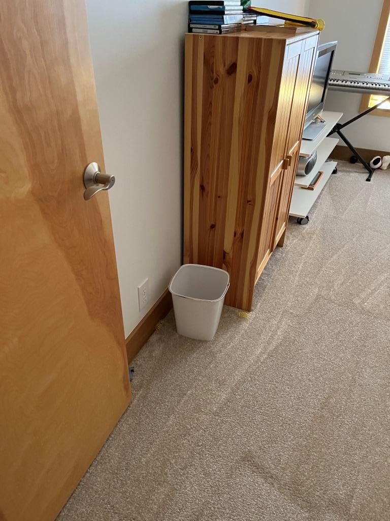
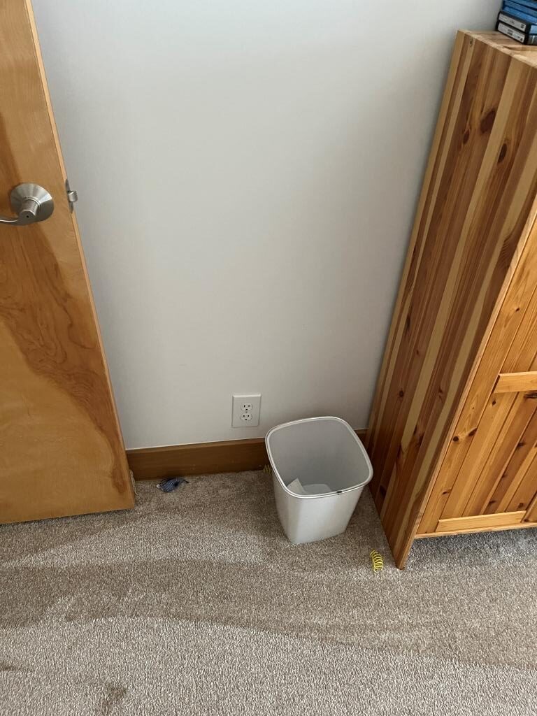
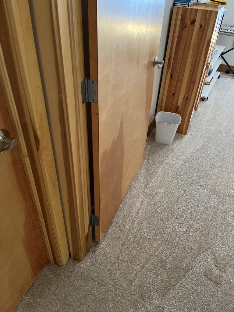
Unfortunately the robot wasn’t really tracking the left ‘wall’ (door surface) – it was just going straight until it ran into the trashcan, and then couldn’t figure out what to do next. As I worked with the code I got WallE3 to track the door OK, but then it still had problems with the trashcan and cupboard. Rather than starting in the hallway for each test, I decided to emulate the configuration in my office for more rapid iterations. Here’s the actual guest bedroom configuration:

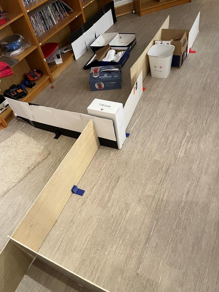
And here is the simulated guest room configuration in my office:

Simulation of guest room configuration

And here is a short video showing a mostly successful run in the above simulated guest room configuration:

The telemetry from the run is shown below:

The salient events from the telemetry:

  • 0.6 – 2.1 sec: tracks left wall
  • 2.1 sec: detects WALL_OFFSET_DIST_AHEAD anomaly.
  • 2.1 – 7.6 sec recovers from WALL_OFFSET_DIST_AHEAD and starts tracking left wall again
  • 7.7 – 9.2 sec tracks left wall (simulated doorway into guest br)
  • 9.2 sec detects WALL_OFFSET_DIST_AHEAD anomaly (end of simulated door?)
  • 9.3 – 10.7 sec: recovers from WALL_OFFSET_DIST_AHEAD and starts tracking left wall again
  • 10.7 – 12.1 sec: tracks left wall
  • 12.1 sec: detects WALL_OFFSET_DIST_AHEAD anomaly. I think this is caused by the box (the simulated near end of the cupboard). This time the anomaly recovery calls ChooseBetterTrackingSide() with an average heading value of 93.1º. The result of this algorithm is 9 votes for left side, 0 for right. The robot starts tracking the left wall with an initial offset of 17.9cm, which is too close, and this causes ‘CaptureWallOffset()’ to be called. CaptureWallOffset() makes a 90º CCW turn to face the left wall, and then calls ‘MoveToDesiredFrontDistCm()’ to move (backup) to a front distance of 30cm. Once this is accomplished, a 90º CW turn is made to re-parallel the left wall, and then ‘RotateToParallelOrientation(LEFT)’ is called to complete the orientation operation.
  • 29.9 – 31.9 sec: tracks left wall (the simulated cupboard face).
  • 31.9 sec: an EXCESS_STEER_VAL anomaly is detected after the robot runs off the end of the simulated cupboard face

02 October 2023 Update:

Having solved the problem of getting from the hallway into the guest bedroom, there remained the problem of negotiating a ‘cul-de-sac’ at the far end of the cupboard, which I simulated in my office as shown in the following video:

And here is the telemetry from the run:

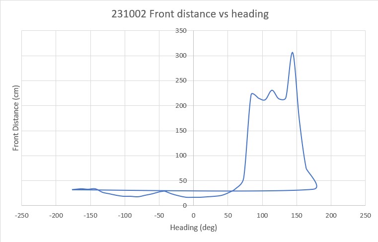
The robot tracks the left wall properly for the first 2.5sec, but then gets trapped in the ‘cul-de-sac’, and eventually resorts to calling a ‘RunToDaylight()’ function to get itself unstuck. RunToDaylight() calls ‘RotateToMaxDistance()’ which performs a full 360º rotation, memorizing the front distance and heading at each step. After the full rotation, the robot turns to the heading associated with the peak front distance and heads that way. As can be seen from the video, this works very well, but over the course of several runs the robot hit the corner of the wall a couple of times because the ‘peak’ heading was recorded just as the front distance sensor (but not necessarily the robot itself) cleared that corner. Here’s an excel plot that shows the issue.

Looking at the plot, it is clear that any heading from about 83 to 150º would suffice, so maybe picking the peak value isn’t so smart. Maybe picking the median value above some distance threshold (like maybe 1.5-2.0 meters) would be a better bet.

04 October 2023 Update:

As I was drifting off to sleep last night, I was mentally reviewing the above ‘run to daylight’ experiment and it struck me that WallE3 had ignored a perfectly good trackable wall segment (at about 31sec, step 22, 94.4º, 215cm in the above 360º search). It occurred to me that I should be searching for the point(s) where WallE3 is parallel or mostly parallel to a wall, with a meter or more of front distance available.

I think I might be able to use a “Figure of Merit” (FoM) defined as the front distance divided by the left or right steering value to detect the optimum travel direction. Steering values vary from 0 to +/-1 so it would need to be abs(FrontD/SteerVal), and it would be maximum at the point where steerval is minimum and front distance is maximum.

One fly in the ointment is the case where steerval is == 0; that would cause FrontD/steerval to be undefined – oops! So I think I need to modify the function that retrieves steervals from the Teensy to limit steerval to something like .001, so the FoM wouldn’t go above a few thousand (10/07/24 note: This was done in ‘GetRequestedVL53l0xValues()’)

Also, I need to figure out how to sort through the 360º search results. I would like to wind up with an array of steervals sorted in decreasing magnitude order, with a companion array of headings so Hdg[i] <–> Steerval[i]. Not sure how to do this yet, but it sounds promising!

07 October 2023 Update:

After some web searching and experimentation, I now have a program that can sort a ‘master’ array and one or more ‘slave’ arrays such that the slave array is rearranged into the same order as the master. See this post for all the gory details.

Now I think I have the tools to address the ‘guest bedroom problem’, as follows:

  • Make the same 360º rotation as before, saving L/R steervals, headings, and front distances into separate 36-element arrays.
  • Sort the above arrays, using front distances as the master, and the others as slaves.
  • Find the element in the front distance array that is greater than a set threshold (say 150cm), has an associated steerval <= (MAX_STEERVAL / 2) and produces the highest ‘FoM’ as described above. Turn to the heading associated with this element, and start tracking that side.
  • If no front distance element / steerval combination satisfies the above criteria, then turn to the heading associated with the middle element of the first/only set of front distance values above the above distance threshold and move forward until another anomaly is detected.

11 October 2023 Update:

I think I’m going to need to save/sort the L/R distances in addition the values listed above, for a total of six parameters; L/R distances, L/R steervals, Hdg, and Front distance. The FrontD array would be the ‘master’ array, and the other five would be ‘slave’ arrays. I could modify my current QuickSort() routine to do all five slave arrays at once (by adding four more ‘swap’ lines in two places in ‘partition’) but this would also require modifying the signatures of QuickSort(), partition() – yuk! I could also simply call ‘QuickSort()’ five times (once for each ‘slave’ array) with the unsorted FrontD array as the master each time. I like this latter approach as it preserves more of the generality of the ‘QuickSort()’ routine.

To do this, I’ll have to define all six arrays at global scope with the following memory requirements:

  • uint16_t FrontD[36]: 2 bytes/value, 36 values –> 72 bytes
  • float Hdg[36]: 4 bytes/value, 36 values –> 144 bytes
  • float LeftSteer[36]: 4 bytes/value, 36 values –> 144 bytes
  • float RightSteer[36]: 4 bytes/value, 36 values –> 144 bytes
  • float LeftDist[36]: 4 bytes/value, 36 values –> 144 bytes
  • float RightDist[36]: 4 bytes/value, 36 values –> 144 bytes

for a total of 4*144 + 72 = 648 bytes. The current memory requirements for WallE3_QuickSort_V3 on a Teensy 3.5 is:

So another 648 bytes is not going to be a problem. After defining and initializing the additional four arrays and recompiling, I got:

So the increase from 115248 to 115312 in program size and from 7728 to 8304 bytes wasn’t enough to even move the percentages – woohoo!

16 October 2023 Update:

After getting the ‘one master and five slave array’ quicksort algorithm working, I did some more testing in my office. The test configurations that featured side walls within tracking distance (100cm) worked very well; however, when I simulated the configuration where no trackable side walls could be found, the robot consistently failed to orient to the most open direction – instead it wound up pointing to one edge or the other of the ‘open direction’ wedge. The algorithm I was using was to use the heading associated with the middle entry of the first N (reverse sorted) front distances.

Then I tried using the middle entry of the first N (reverse sorted) heading values, where the group of heading values to be sorted were the ones associated with the above first N reverse-sorted front distances. However, this didn’t work either, because when I designed the experiment, the maximum distances naturally occurred around 180º from the starting orientation, and this meant that the first N headings included both positive and negative values. When reverse-sorted, the positive values were at the top as expected, but the negative values got sorted to the bottom – oops!

The solution to the problem was to create a temporary heading array, fill it with the heading values associated with the first N front distances as before, but with the heading values modified to fit into the 0-359º range (by adding 360 to negative values). The result of this trick was to ‘homogenize’ the headings so they were all sequential, and then selecting the median value did indeed point the robot in the correct direction, as shown in the following short video and telemetry output.

In the above telemetry output, the first two values in the Hdg array associated with the reverse-sorted FrontD array are negative, so if the Hdg array is reverse sorted to find the best RunToDaylight heading, the two headings associated with the longest open run aren’t considered unless they are first modified such that all headings lie in the 0-360 range. The ‘tempHdg’ array accomplishes this.

After the above successful test of the new ‘RunToDaylight’ capability, it is time to integrate this into the rest of the program. At the moment the code is contained in ‘RunToDaylightV2’ and it is only called from ‘#pragma region QUICKSORT_TEST in setup(). In the mainline code, ‘RunToDaylight’ is called from ChooseBetterTrackingSide() when the ‘Better Side’ can’t be determined.

ChooseBetterTrackingSide() is called from HandleExcessSteervalCase() when a trackable wall is found on both sides, and a determination has to be made on how to proceed. So, it appears that all I have to do is comment out (or delete) the QUICKSORT_TEST #pragma region and RunToDaylightV2 will be called as necessary.

After making the necessary changes, I made a long ‘field test’, starting in our entrance hallway and going through the kitchen and down the bedroom hallway to the end, and then once again into the guest bedroom. This all worked perfectly, and I was pleased to see that ‘RunToDaylightV2()’ was called at the end. See the accompanying video and the telemetry for all the details:

17 October 2023 Update:

I tried another Guest Bedroom ‘field test’, with different results this time, as shown in the accompanying video and telemetry:

Stay tuned,

Frank

WallE3_Complete_V5 Print Timing Issue

Posted 24 September 2023,

This post addresses the problem I have started to see regarding print buffer overflow due to the decreased time (now 50mSec) between environment updates. When running longer field tests, I have started to see many lines where telemetry printout has become garbled, with the next line of printout starting before the previous line has finished, as shown in the accompanying printout

In the above printout, you will notice that the horizontal scrollbar is much smaller than normal, indicating the line lengths are much longer than normal, and the portion that is visible is really really ugly!

So, what to do? I ran a search through my almost 7000 lines of code for ‘gl_pSerPort->printf(‘ to see how big of a problem I’m looking at, and the search came back with some 400+ hits – ouch! One thought would be to put an ‘if’ statement around each printf call and use an ‘EllapsedMillisec’ variable to limit calls to, say, every 100 or 200 msec, but doing that for 400+ calls would get pretty tedious. Another thought is to abstract all these print statements into a function, and have the time spacing internal to the function. So the function call would look something like:

and the function internals would look something like:

The problem with the function internals is the argument list would have to match the contents of ‘formatstr’, which means I would have to have an overload for every unique format, and changing anything would be a hassle, as I would have to find and edit the correct overload – yuck!

OK, more thought needed on this – maybe the ‘if’ statement is the way to go (maybe a macro?)

Another thought that just came up; if I filter all print statements by an elapsed time gate, that might actually filter out important one-time error information – ouch! This potential problem suggests adding a priority value to the ‘LogPrint()’ function, so the function might look like:

And good programming technique would demand that the PRIORITY_CODE have a default value, which (for Arduino programming) would require that every overload have a function declaration at the top of the program – yuck! yuck!

Maybe it would be easier to just put the

around each and every ‘low priority’ print statement (all 400+ of them)? yuck! yuck! yuck!

After thinking about this some more, it occurs to me that this problem may be a lot smaller than I think. The primary culprit is the long telemetry string printed out each WALL_TRACK_UPDATE_INTERVAL_MSEC (currently set to 50mSec). It may well be that I only need to guard this one print statement and 99% of the time that will do the trick. As I find other printout statements that are causing problems, I can treat them as well.

25 September 2023 Update:

I did a search for ‘gl_pSerPort->printf(‘ but bypassed everything in setup() and loop(). Starting in TrackLeftWallOffset() in the ‘while (gl_LastAnomalyCode == ANOMALY_NONE )’ block I put an ‘if(mSecSinceLastTelemetryUpdate > PRINT_INTERVAL_MSEC)’ guard around the call to ‘OutputTelemetryLine(TRACKING_LEFT)’, as shown below:

26 September 2023 Update:

After guarding the ‘OutputTelemetry()’ call in both TrackLeftWallOffset() and TrackRightWallOffset(), I ran another field test, and saw that telemetry output was clean, and now coming in 0.1sec intervals, as intended – yay!

Stay tuned,

Frank

Garmin LIDAR-Lite V4/LED Distance Compensation

Posted 20 September 2023

Last February I changed out the Pulsed Light ‘Blue Label’ LIDAR system on WallE3 for the newer and better Garmin LIDAR-Lite V4 LED time-of-flight distance sensor (see this post and this post), and it has been working very well for me since then. However, I recently had occasion to re-visit my ‘MoveToDesiredForwardDistance()’ function, and found that WallE3 wasn’t doing a very good job of stopping where it should; it was often stopping 8-10cm farther away from the wall than desired.

Going back through the above two posts from last February, I found that this was something I had noticed at the time, but hadn’t worried about as precise front distances are generally not needed. However, precise front distances are required for the ‘MoveToDesiredForwardDistance()’ operation, so it is time to think about distance compensation, at least for distances less than 1m.

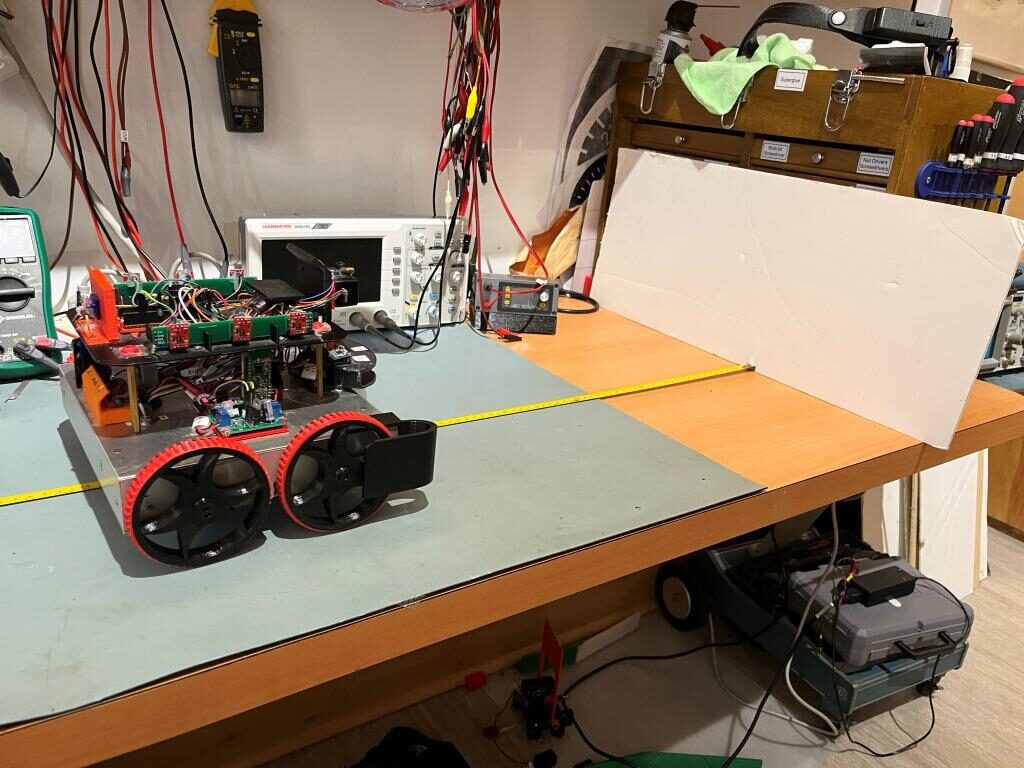
I started by redoing the distance measurement experiment shown in my initial study, as shown in the photo below:

Distance Compensation Measurement Setup

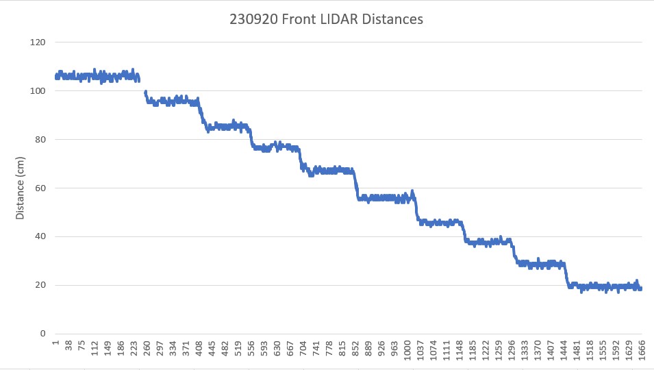
This produced the following plot:

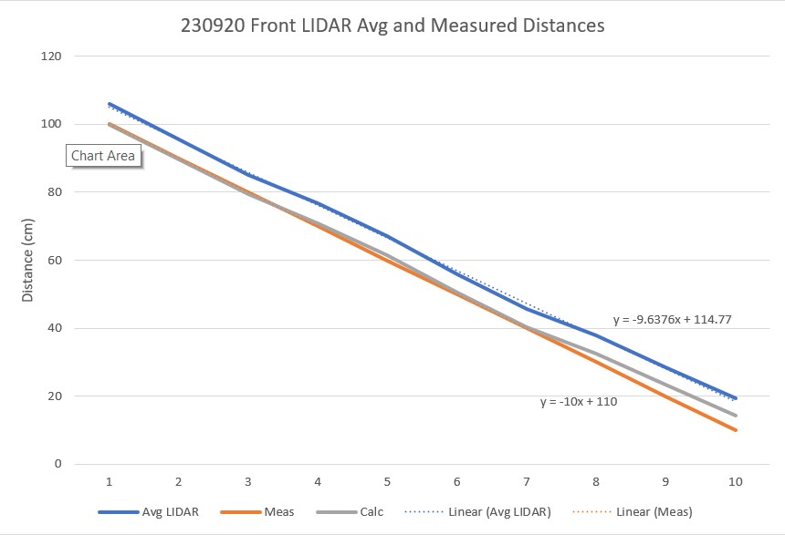
Then I took the average from each of the above ‘stairsteps’ and plotted that against the actual distances, arriving at the following plot:

Avg LIDAR Distance, Meas Distance, and Calculated Compensated Distance

In the above chart, I used Excel’s ‘trendline’ tool to display the ‘best fit’ linear equation for both the plot of average values and the plot of actual distances. Of course the equation for the actual distances is exact, but the average values show a consistent too-high measurement.

Then I created a compensation function to make the LIDAR values look like measured values, and came up with y_comp = =0.987*(y_meas – 4.77), and plotted this line (shown in gray above). This compensation works very well for values down to about 40cm, but not so much below that. A separate compensation equation may be required for this section.

21 September 2023 Update:

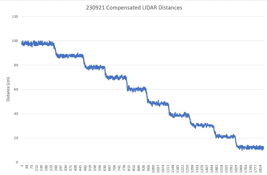
I modified WallE3’s ‘GetFrontDistCm()’ function to include the above compensation expression and re-ran the test from yesterday, with the following result:

Compensated LIDAR Distance Measurements

As can be seen in the above plot, the compensated distance measurements track the actual distances quite nicely. This should result in the ‘MoveToDesiredFrontDistCm()’ function behaving much better than it did before front distance compensation.

Stay Tuned!

Frank