Posted 14 January 2022
After finding and fixing the connector problem that prevented the IR Homing Teensy 3.2 module from communicating via I2C with the Teensy 3.5 main controller, I was ready to move on to some real IR homing tests.
For this effort, I decided to change the IR homing algorithm over from the PID library to my home-grown PID routine, discussed here. In the process, I realized that my PIDCalcs() function was overly complex; in particular the ‘sampletime’ calling argument is never used inside the function, as a regular interval is assumed. In all my PID implementations, this is a valid assumption, as I use an ‘elapsedMillisec’ object to enforce regular calls to PIDCalcs(). After eliminating this parameter, the PIDCalcs() function now looks like this:
|
1 2 3 4 5 6 7 8 9 10 11 12 13 14 15 16 17 18 19 20 21 22 23 24 25 26 27 28 29 30 31 32 33 34 |
double PIDCalcs(double input, double setpoint, double& lastError, double& lastInput, double& lastIval, double& lastDerror, double Kp, double Ki, double Kd) { //Purpose: Encapsulate PID algorithm so can get rid of PID library. Library too cumbersome and won't synch with TIMER5 ISR //Inputs: // input = double denoting current input value (turn rate, speed, whatever) // setpoint = double denoting desired setpoint in same units as input // sampleTime = int denoting sample time to be used in calcs. // lastError = ref to double denoting error saved from prev calc // lastInput = ref to double denoting input saved from prev calc // Kp/Ki/Kd = doubles denoting PID values to be used for calcs // Output = ref to double denoting output from calc // Notes: // 01/13/22 sampleTime input parameter removed as it was never used. This is OK as long as PIDCalcs // is called at regular intervals. double error = setpoint - input; lastIval += (Ki * error); //11/16/21 rev to clamp integral term lastIval = (lastIval > MOTOR_SPEED_MAX) ? MOTOR_SPEED_MAX : lastIval; lastIval = (lastIval < MOTOR_SPEED_OFF) ? MOTOR_SPEED_OFF : lastIval; double dErr = (error - lastError); /*Compute PID Output*/ //11/16/21 rev to subtract differential term rather than add. double output = Kp * error + lastIval - Kd * dErr; /*Remember some variables for next time*/ lastError = error; lastInput = input; lastDerror = dErr; return output; //added 09/03/21 } |
And the calling routine for this round of testing (not using distance information) looks like this:
|
1 2 3 4 5 6 7 8 9 10 11 12 13 14 15 16 17 18 19 20 21 22 23 24 25 26 27 28 29 30 31 32 33 34 35 36 37 38 39 40 41 42 43 44 45 46 47 48 49 50 51 52 53 54 55 56 57 58 59 60 61 62 63 64 65 66 67 68 69 70 71 72 73 74 |
bool IRHomeToChgStnNoPings(int initleftspeed, int initrightspeed) { //Purpose: Home in to charging station without distance information //Inputs: //Outputs: // robot homes to charging station //Plan: // Step2: Initialize PID for homing //Notes: // 03/19/17 rev to add initial left/right speed vals to calling sig // 01/14/22 rev to use PIDCalcs vs PID library bool result = true; //added 01/16/19 to suppress warning //Step2: Initialize PID for homing IRHomingSetpoint = 0; double lastError = 0; double lastInput = 0; double lastIval = 0; double lastDerror = 0; bool bChgConnect = false; //01/08/22 no longer using ISR, so have to generate locally while (!bChgConnect) { //05/02/20 turn on Laser digitalWrite(RED_LASER_DIODE_PIN, HIGH); //01/30/17 added to kill motors remotely CheckForUserInput(); if (MsecSinceLastIRHomingAdj >= MSEC_PER_IR_HOMING_ADJ) { MsecSinceLastIRHomingAdj -= MSEC_PER_IR_HOMING_ADJ; UpdateIRHomingValues(); if (!isnan(IRHomingLRSteeringVal))//skip bad values { //reversed 01/11/22 - 01/14/22 - reversed it back again leftspeednum = initleftspeed + IRHomingOutput; rightspeednum = initrightspeed - IRHomingOutput; //limit wheel speeds to valid range (0-255) leftspeednum = (leftspeednum > MOTOR_SPEED_MAX) ? MOTOR_SPEED_MAX : leftspeednum; leftspeednum = (leftspeednum < MOTOR_SPEED_OFF) ? MOTOR_SPEED_OFF : leftspeednum; rightspeednum = (rightspeednum > MOTOR_SPEED_MAX) ? MOTOR_SPEED_MAX : rightspeednum; rightspeednum = (rightspeednum < MOTOR_SPEED_OFF) ? MOTOR_SPEED_OFF : rightspeednum; UpdateRearLEDPanel(leftspeednum, rightspeednum); MoveAhead(leftspeednum, rightspeednum); } bChgConnect = IsChargerConnected(bChgConnect); } } if (bChgConnect) { Serial.print("Charger Connected at "); Serial.println(millis()); result = true; //added 01/16/19 to suppress warning } else //added 12/28/20 for debug. { myTeePrint.printf("In IRHomeToChgStation: This code block should never execute! Stopping Program!"); StopBothMotors(); while (true) { } } return result; //added 01/16/19 to suppress warning } |
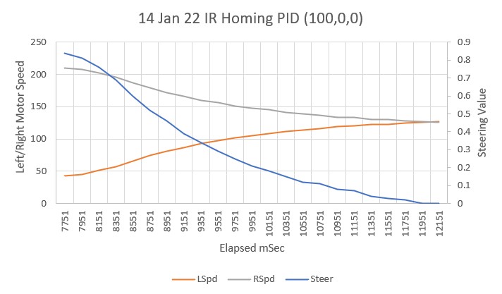
The ‘steering value’ output from the IR Homing beacon demodulator ranges from -1 to +1, and motor speeds range from 0 to 255 with a median value of 127. So, I started testing WALL-E3 with a PID of 100,0,0 – the idea being that a max output of +/- 1 from the demodulator would produce an output of +/- 100, which, when used to modulate motor speeds from the median value of 127 would produce motor speeds of 227/27 in one direction and 27/227 in the other. In other words, a Kp value of 100 should produce significant motor speed modulation without hitting the motor speed limits in either direction.
I set up a small test range in my office, and made a couple of runs. Here’s a short video showing on of the runs, and an Excel plot showing steering value and motor speeds vs time.
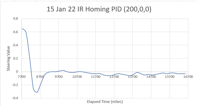
The next step is to increase the Kp value to the point where oscillations occur, as the starting point for the Zeigler-Nichols PID tuning method. For PID = (200,0,0) I got this behavior.
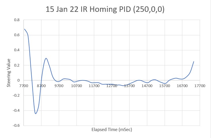
And for PID = (250,0,0),
And Kp = 300
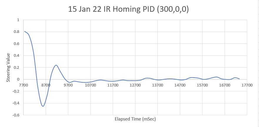
Looks like Kp = 300 might be a good place to start. So, according to the Zeigler-Nichols PID tuning method, I should use Kp = 0.5Kc = 150, Ki = 0.45Kc = 135, Kd = 0.6Kc = 180. Using these values, I get:
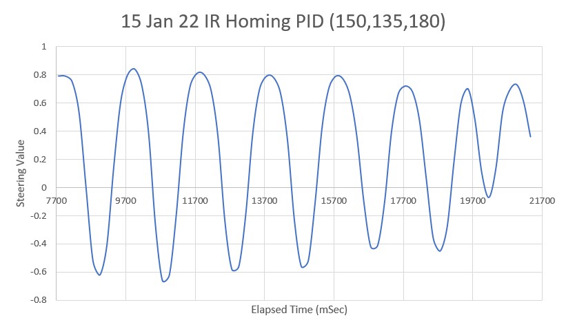
Needless to say, this is NOT what I had in mind! Clearly I erred somewhere along the way. Abandoning the Z-N tuning algorithm, I turned to the ‘manual’ tuning procedure I have used in the past (also discussed in the Z-N article): With Ki, Kd set to 0, increase Kp until the system oscillates, but before it becomes unstable. Then increase Ki until the oscillations stop. Then increase D until “the system achieves an acceptable quick loop to its set-point” (whatever that means).
Starting with a Kd of 200, I increased Ki in increments of 50 to get:
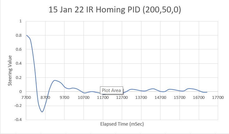
This looks pretty good, even as a first try. However, when compared to the original PID = (200,0,0) plot (shown below), it looks like the Ki value of 50 didn’t actually do very much one way or the other.
Increasing Ki to 100 produces the following plot.
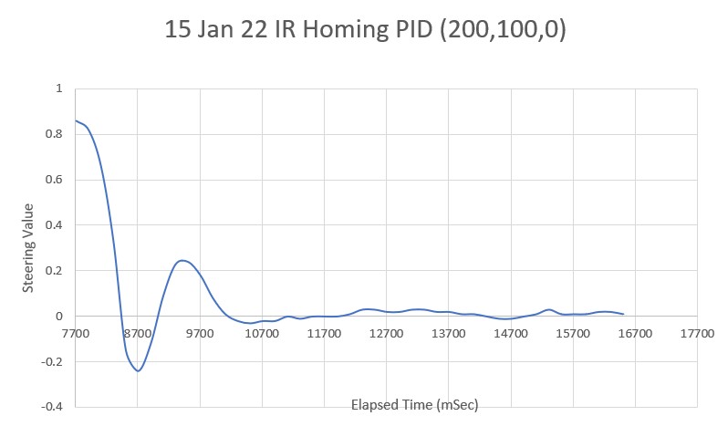
Not much, if any, improvement. Keeping Kp = 200 and Ki = 100, try increasing Kd in increments of 25. The first increment (Kd = 25) produced a significant change, as shown below:
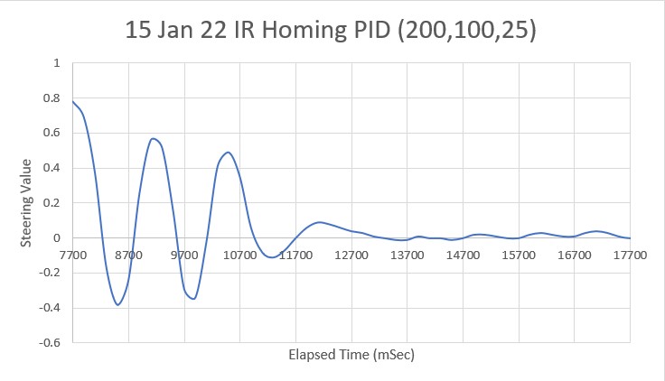
Which leads me to believe the 25 increment is way too much. Trying 10, we get:
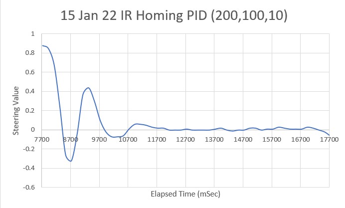
PID = 200,100,10 is much nicer than the Kd = 25 version, but there was an annoying little ‘jag’ off-course right at the end – don’t know why. Just for grins I tried PID = (150,100,10):
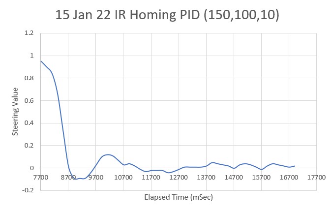
And this looks pretty good, actually. I think I may run with these values for a while and see how it works. Here’s the video of the above run:
One final note before leaving this subject. I added some code to IRHomeToChgStnNoPings() to measure the time required to run through each motor speed determination loop. The code simply turns ON a digital output at the start, and turns it OFF again at the end. The loop runs every 200 mSec (the current value of MSEC_PER_IR_HOMING_ADJ), but the time required to do everything is only about 1.5 mSec. In other words, the Teensy sits idle for about 99% of the time while homing to the charging station. Or to put it another way, I could run the loop 10 times faster (20mSec vs 200mSec) and the Teensy wouldn’t even break a sweat!
Stay tuned,
Frank