Posted 27 November 2020
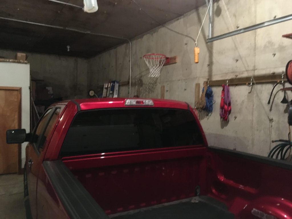
After my recent right shoulder surgery, I have been looking for ways to get back into BBall shooting practice. However, the combination of Covid-19 lockdowns and the oncoming winter weather has drastically reduced my options for shooting practice. Not to be dissuaded from BBall practice, I figured out a way of moving my practice area from my driveway outside the garage inside the garage. As it turns out, our earth-sheltered house boasts an attached earth-sheltered two-car garage with a 12′ interior ceiling and no vertical support beams (I insisted on this in the design, and paid the extra cost, knowing from prior experience that interior support columns in a two-car garage was a bad thing.
Still not quite perfect, as even a 12′ ceiling isn’t quite enough room for a 10′ high BBall rim and enough headroom for practical shooting practice. So, I decided to mount my new practice rim at 9′ vs 10′, leaving 3′ of headroom. Obviously this isn’t ideal, but I figured a lot of practice on a 9′ rim was much better than no practice on a 10′ rim ;-).
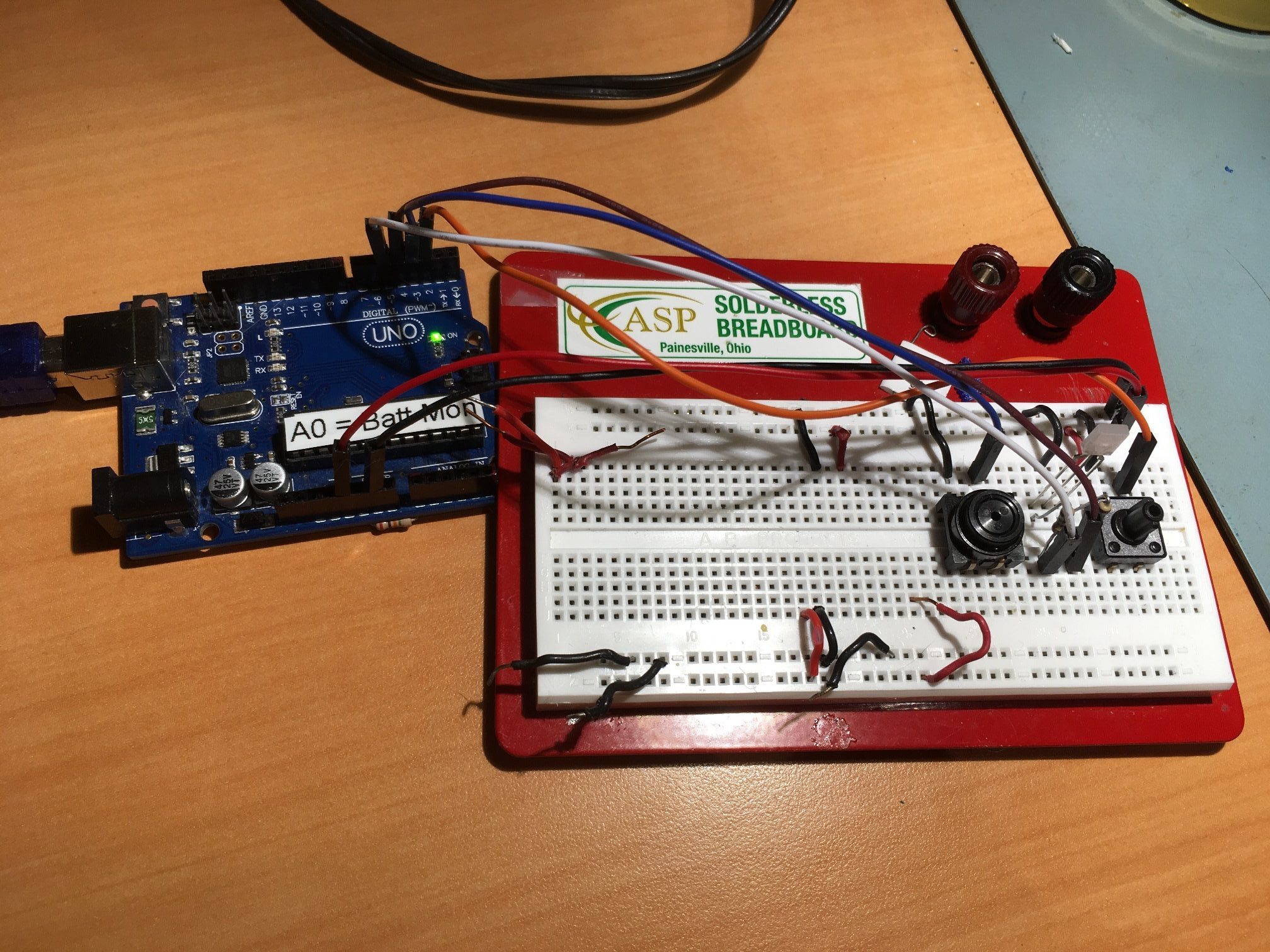
As I started to shoot in my new practice gym, I realized I also now needed a way to record hits and misses so I could keep a running ‘made shots’ percentage. My short-term memory degradation due to being an old fart has made it almost impossible to do this in my head, and besides, what could be better than being able to combine my love of BBall, my love of programming, and my love for hardware/software projects? That’s at least a trifecta if not a quadfecta (and that is actually a word!). So, I programmed up a Windows program in C# to display ‘Hits’, ‘Attempts’, and ‘Hit Percentage’, and used an Arduino microcontroller to interface to two push-buttons – one for a hit, and the other for a miss. The arduino talks to the Windows program via a serial port over the USB cable, and the Windows program displays everything in a readily visible way. My idea was to use foot switches for the input so it would be easy to provided the needed hit/miss inputs without having to break out of a shooting rhythm. So, I jumped up on Thingiverse and found a neat, rugged footswitch by ‘vandenmar’. I needed two switches, so I modified vandenmar’s design by adding an additional cable routing trench out to the other side of the switch (so the switch cable can be routed in from the left or right-hand side of the switch).
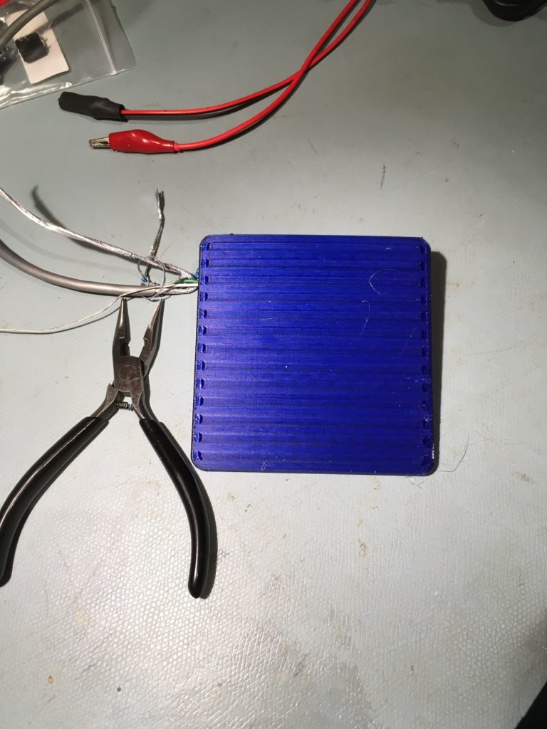
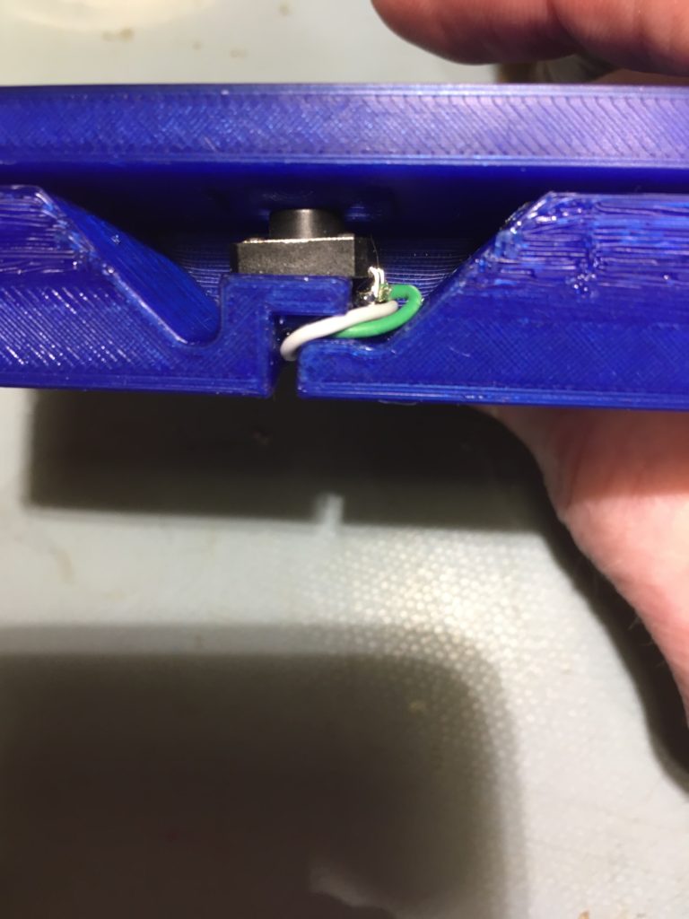
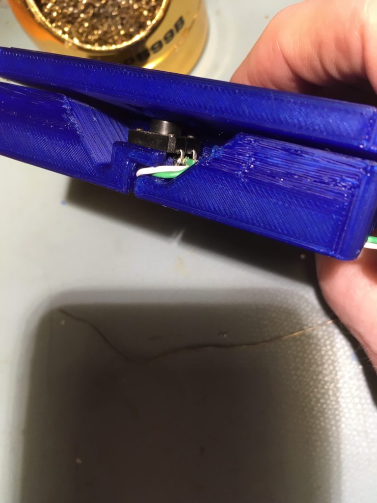
Here’s a photo of the Arduino switch contoller
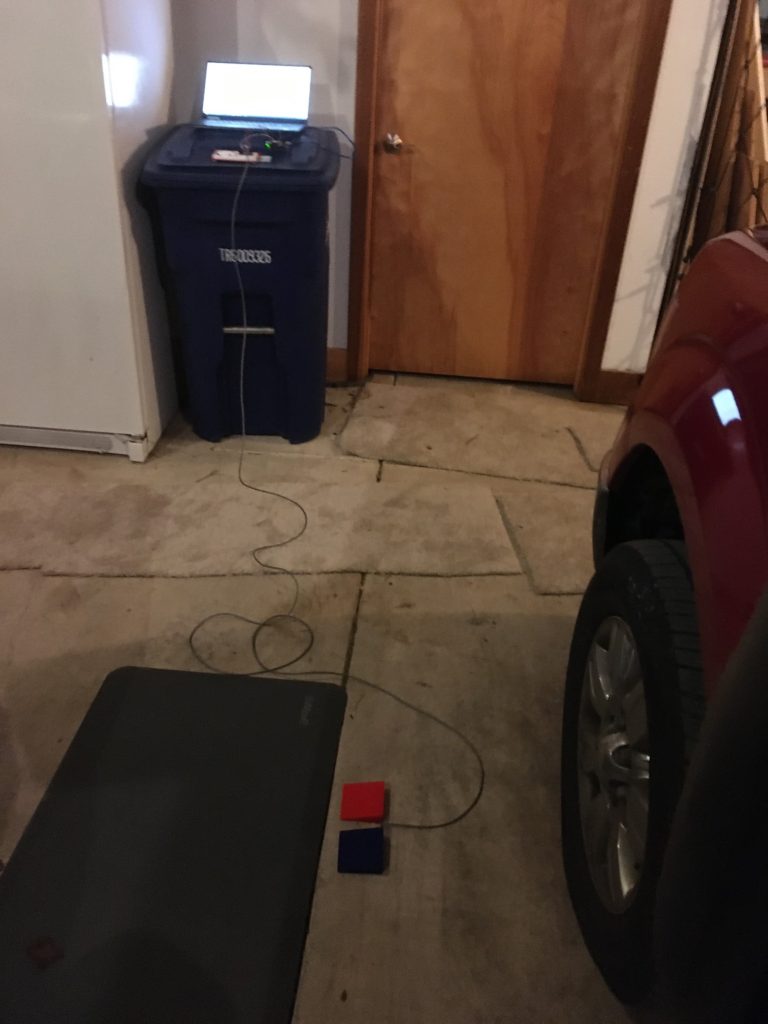
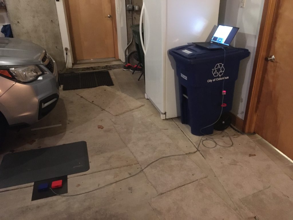
After getting all the pieces together, this is how it looks in my garage. The red footswitch is for ‘makes’ and the blue one is for ‘misses’.
This setup worked pretty well, but it still wasn’t quite ready for prime time. The UNO & breadboard were, well, breadboards, and not very mechanically robust. I was afraid I would spend more time repairing the breadboard than I would actually shooting, so I decided I needed to move from a breadboard to a more finished project. In addition, the Windows program I was using to display stats needed some work, so both sides (Windows and Arduino) needed some TLC.
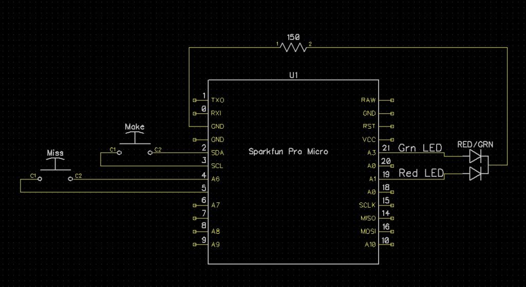
I happened to have a Sparkfun Pro Micro module laying around in my parts bin, so I decided I would change out the UNO for the much smaller Pro Micro. With only two pushbutton switches and a Red/Green LED, the Pro Micro has plenty of I/O for the project. Here’s the Pro Micro version of the hardware layout.
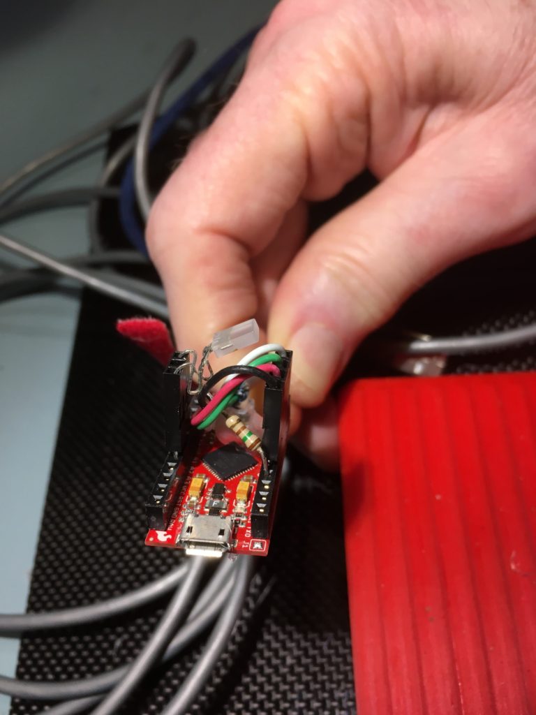
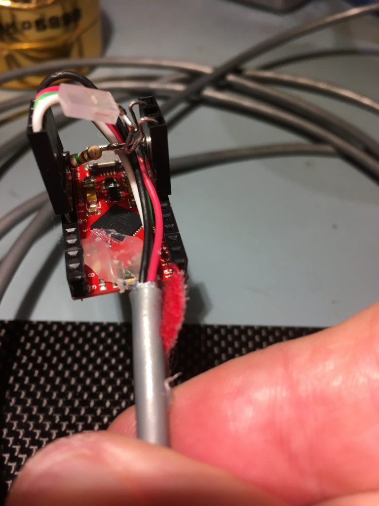
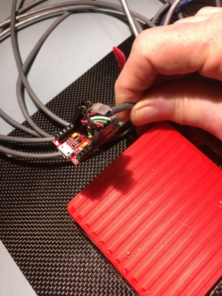
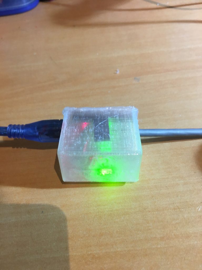
So then I opened up my trusty Open SCAD ’rounded box with lid’ script and printed up a translucent enclosure, shown below
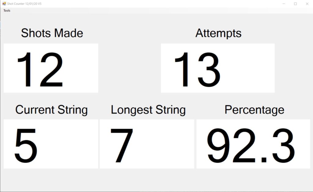
Next I updated the Windows program to show Makes, Misses, Percentage makes, and number of shots made in a row, along with the longest run of made shots for this session, as shown below
And here is the ‘final’ setup in my garage:
Here’s the schematic for the Sparkfun Pro Micro setup
And here is a short video showing the system in action.
At 0:43 into the above video you can see the green ‘Make’ LED illuminate in the background when I pressed the red ‘Make’ footswitch, and at 1:25 you can see me pressing the blue ‘Miss’ footswitch.
Stay tuned!
Frank