I have been running some wall-tracking tests with Wall-E2 and the new VL53L0X sensor array arrangement, but have been having poor results, especially with offset capture. After a bunch of test runs, I started to think that the distances aren’t updating fast enough to keep up with the robot’s forward speed, so it runs into the wall before it knows that it has gotten too close
Looking at the Teensy 3.5 I2C Slave code that manages the sensor array, I see the following loop() code
|
1 2 3 4 5 6 7 8 9 10 11 12 13 14 15 16 17 18 19 20 21 22 |
void loop() { RF_Dist_mm = lidar_RF.readRangeSingleMillimeters(); RC_Dist_mm = lidar_RC.readRangeSingleMillimeters(); RR_Dist_mm = lidar_RR.readRangeSingleMillimeters(); RightSteeringVal = (RF_Dist_mm - RR_Dist_mm) / 100.f; //rev 06/21/20 see PPalace post LF_Dist_mm = lidar_LF.readRangeSingleMillimeters(); LC_Dist_mm = lidar_LC.readRangeSingleMillimeters(); LR_Dist_mm = lidar_LR.readRangeSingleMillimeters(); LeftSteeringVal = (LF_Dist_mm - LR_Dist_mm) / 100.f; //rev 06/21/20 see PPalace post Serial.printf("%lu\t%d\t%d\t%d\t%d\t%d\t%d\t%2.2f\t%2.2f\n", millis(), LF_Dist_mm, LC_Dist_mm, LR_Dist_mm, RF_Dist_mm, RC_Dist_mm, RR_Dist_mm, LeftSteeringVal, RightSteeringVal); delay(100); } |
And I get the following output:
|
1 2 3 4 5 6 7 8 9 10 11 12 |
Msec LFront LCtr LRear RFront RCtr RRear LSteer RSteer 1578 578 557 456 193 256 296 1.22 -1.03 1896 587 572 446 193 261 297 1.41 -1.04 2214 593 563 447 193 268 286 1.46 -0.93 2531 587 580 450 193 248 295 1.37 -1.02 2849 581 554 444 193 253 297 1.37 -1.04 3166 589 568 450 192 259 294 1.39 -1.02 3484 582 579 449 195 254 290 1.33 -0.95 3801 579 562 459 194 263 291 1.20 -0.97 4119 590 559 464 196 263 288 1.26 -0.92 4437 572 594 465 192 253 297 1.07 -1.05 4754 595 587 446 190 261 293 1.49 -1.03 |
Looking at the timestamps, it appears that a measurement cycle takes about 200 mSec, taking into account the added 100 mSec delay from the delay(100); statement. This is consistent with the default 30 mSec measurement time for a single VL53L0X, but unfortunately this is much greater than the default 100 mSec PID controller update rate.
The VL53L0X can make measurements faster, but at the cost of lower accuracy. In my case, the increased accuracy from a 30 mSec measurement time is useless if it isn’t fast enough to keep up with the robot. Searching around the net, I found this post on the Pololu support forum, dealing with just this problem. So, I modified my Teensy 3.5 I2C Slave program to use ‘continuous measurements and the shorter (20 mSec vs 30 mSec) timing budget, as follows:
|
1 2 3 4 5 6 7 8 9 10 11 12 13 14 15 16 17 18 19 20 21 22 23 24 25 26 27 28 29 30 31 32 33 34 35 36 37 38 39 40 41 42 43 44 45 46 47 48 49 50 51 52 53 54 55 56 57 58 59 60 61 62 63 64 65 66 67 68 69 70 71 72 73 74 75 76 77 78 79 80 81 82 83 84 85 86 87 88 89 90 91 92 93 94 95 96 97 98 99 100 101 102 103 104 105 106 107 108 109 110 111 112 113 114 115 116 117 118 119 120 121 122 123 124 125 126 127 128 129 130 131 132 133 134 135 136 137 138 139 140 141 142 143 144 145 146 147 148 149 150 151 152 153 154 155 156 157 158 159 160 161 162 163 164 165 166 167 168 169 170 171 172 173 174 175 176 177 178 179 180 181 182 183 184 185 186 187 188 189 190 191 192 193 194 195 196 197 198 199 200 201 202 203 204 205 206 207 208 209 210 211 212 213 214 215 216 217 218 219 220 221 222 223 224 225 226 227 228 229 230 231 232 233 234 235 236 237 238 239 240 241 242 243 244 |
/* Name: TeensyHexVL53L0XHighSpeedDemo.ino Created: 10/1/2020 3:49:01 PM Author: FRANKNEWXPS15\Frank This demo program combines the code from my Teensy_VL53L0X_I2C_Slave_V2 project with the VL53L0X 'high speed' code from the Pololu support forum post at https://forum.pololu.com/t/high-speed-with-vl53l0x/16585/3 */ /* Name: Teensy_VL53L0X_I2C_Slave_V2.ino Created: 8/4/2020 7:42:22 PM Author: FRANKNEWXPS15\Frank This project merges KurtE's multi-wire capable version of Pololu's VL53L0X library with my previous Teensy_VL53L0X_I2C_Slave project, which used the Adafruit VL53L0X library. This (hopefully) will be the version uploaded to the Teensy on the 2nd deck of Wall-E2 and which controls the left & right 3-VL53L0X sensor arrays */ #include <Wire.h> //using Wire.h here instead of i2c_t3.h for multiple I2C bus access #include <VL53L0X.h> #include "I2C_Anything.h" //local version modified to use Wire.h vs SBWire volatile uint8_t request_type; enum VL53L0X_REQUEST { VL53L0X_CENTERS_ONLY, VL53L0X_RIGHT, VL53L0X_LEFT, VL53L0X_BOTH //added 08/05/20 }; //right side array VL53L0X lidar_RF(&Wire1); VL53L0X lidar_RC(&Wire1); VL53L0X lidar_RR(&Wire1); //left side array VL53L0X lidar_LF(&Wire2); VL53L0X lidar_LC(&Wire2); VL53L0X lidar_LR(&Wire2); //XSHUT required for I2C address init //right side array const int RF_XSHUT_PIN = 23; const int RC_XSHUT_PIN = 22; const int RR_XSHUT_PIN = 21; //left side array const int LF_XSHUT_PIN = 5; const int LC_XSHUT_PIN = 6; const int LR_XSHUT_PIN = 7; const int MAX_LIDAR_RANGE_MM = 1000; //make it obvious when nearest object is out of range //right side array uint16_t RF_Dist_mm; uint16_t RC_Dist_mm; uint16_t RR_Dist_mm; //left side array uint16_t LF_Dist_mm; uint16_t LC_Dist_mm; uint16_t LR_Dist_mm; float RightSteeringVal; float LeftSteeringVal; const int SLAVE_ADDRESS = 0x20; //just a guess for now const int DEFAULT_VL53L0X_ADDR = 0x29; void setup() { Serial.begin(115200); Wire.begin(SLAVE_ADDRESS); //set Teensy Wire0 port up as slave Wire.onRequest(requestEvent); //ISR for I2C requests from master (Mega 2560) Wire.onReceive(receiveEvent); //ISR for I2C data from master (Mega 2560) Wire1.begin(); Wire2.begin(); // wait until serial port opens ... For 5 seconds max while (!Serial && millis() < 5000); pinMode(RF_XSHUT_PIN, OUTPUT); pinMode(RC_XSHUT_PIN, OUTPUT); pinMode(RR_XSHUT_PIN, OUTPUT); pinMode(LF_XSHUT_PIN, OUTPUT); pinMode(LC_XSHUT_PIN, OUTPUT); pinMode(LR_XSHUT_PIN, OUTPUT); //Put all sensors in reset mode by pulling XSHUT low digitalWrite(RF_XSHUT_PIN, LOW); digitalWrite(RC_XSHUT_PIN, LOW); digitalWrite(RR_XSHUT_PIN, LOW); digitalWrite(LF_XSHUT_PIN, LOW); digitalWrite(LC_XSHUT_PIN, LOW); digitalWrite(LR_XSHUT_PIN, LOW); //now bring lidar_RF only out of reset and set it's address //input w/o pullups sets line to high impedance so XSHUT pullup to 3.3V takes over pinMode(RF_XSHUT_PIN, INPUT); delay(10); if (!lidar_RF.init()) { Serial.println("Failed to detect and initialize lidar_RF!"); while (1) {} } //from Pololu forum post lidar_RF.setMeasurementTimingBudget(20000); lidar_RF.startContinuous(); lidar_RF.setAddress(DEFAULT_VL53L0X_ADDR + 1); Serial.printf("lidar_RF address is 0x%x\n", lidar_RF.getAddress()); //now bring lidar_RC only out of reset, initialize it, and set its address //input w/o pullups sets line to high impedance so XSHUT pullup to 3.3V takes over pinMode(RC_XSHUT_PIN, INPUT); delay(10); if (!lidar_RC.init()) { Serial.println("Failed to detect and initialize lidar_RC!"); while (1) {} } //from Pololu forum post lidar_RC.setMeasurementTimingBudget(20000); lidar_RC.startContinuous(); lidar_RC.setAddress(DEFAULT_VL53L0X_ADDR + 2); Serial.printf("lidar_RC address is 0x%x\n", lidar_RC.getAddress()); //now bring lidar_RR only out of reset, initialize it, and set its address //input w/o pullups sets line to high impedance so XSHUT pullup to 3.3V takes over pinMode(RR_XSHUT_PIN, INPUT); delay(10); if (!lidar_RR.init()) { Serial.println("Failed to detect and initialize lidar_RR!"); while (1) {} } //from Pololu forum post lidar_RR.setMeasurementTimingBudget(20000); lidar_RR.startContinuous(); lidar_RR.setAddress(DEFAULT_VL53L0X_ADDR + 3); Serial.printf("lidar_RR address is 0x%x\n", lidar_RR.getAddress()); //now bring lidar_LF only out of reset, initialize it, and set its address //input w/o pullups sets line to high impedance so XSHUT pullup to 3.3V takes over pinMode(LF_XSHUT_PIN, INPUT); delay(10); if (!lidar_LF.init()) { Serial.println("Failed to detect and initialize lidar_LF!"); while (1) {} } //from Pololu forum post lidar_LF.setMeasurementTimingBudget(20000); lidar_LF.startContinuous(); lidar_LF.setAddress(DEFAULT_VL53L0X_ADDR + 4); Serial.printf("lidar_LF address is 0x%x\n", lidar_LF.getAddress()); //now bring lidar_LC only out of reset, initialize it, and set its address //input w/o pullups sets line to high impedance so XSHUT pullup to 3.3V takes over pinMode(LC_XSHUT_PIN, INPUT); delay(10); if (!lidar_LC.init()) { Serial.println("Failed to detect and initialize lidar_LC!"); while (1) {} } //from Pololu forum post lidar_LC.setMeasurementTimingBudget(20000); lidar_LC.startContinuous(); lidar_LC.setAddress(DEFAULT_VL53L0X_ADDR + 5); Serial.printf("lidar_LC address is 0x%x\n", lidar_LC.getAddress()); //now bring lidar_LR only out of reset, initialize it, and set its address //input w/o pullups sets line to high impedance so XSHUT pullup to 3.3V takes over pinMode(LR_XSHUT_PIN, INPUT); if (!lidar_LR.init()) { Serial.println("Failed to detect and initialize lidar_LR!"); while (1) {} } //from Pololu forum post lidar_LR.setMeasurementTimingBudget(20000); lidar_LR.startContinuous(); lidar_LR.setAddress(DEFAULT_VL53L0X_ADDR + 6); Serial.printf("lidar_LR address is 0x%x\n", lidar_LR.getAddress()); Serial.printf("Msec\tLFront\tLCtr\tLRear\tRFront\tRCtr\tRRear\tLSteer\tRSteer\n"); } void loop() { //from Pololu forum post RF_Dist_mm = lidar_RF.readRangeContinuousMillimeters(); RC_Dist_mm = lidar_RC.readRangeContinuousMillimeters(); RR_Dist_mm = lidar_RR.readRangeContinuousMillimeters(); RightSteeringVal = (RF_Dist_mm - RR_Dist_mm) / 100.f; //rev 06/21/20 see PPalace post //from Pololu forum post LF_Dist_mm = lidar_LF.readRangeContinuousMillimeters(); LC_Dist_mm = lidar_LC.readRangeContinuousMillimeters(); LR_Dist_mm = lidar_LR.readRangeContinuousMillimeters(); LeftSteeringVal = (LF_Dist_mm - LR_Dist_mm) / 100.f; //rev 06/21/20 see PPalace post Serial.printf("%lu\t%d\t%d\t%d\t%d\t%d\t%d\t%2.2f\t%2.2f\n", millis(), LF_Dist_mm, LC_Dist_mm, LR_Dist_mm, RF_Dist_mm, RC_Dist_mm, RR_Dist_mm, LeftSteeringVal, RightSteeringVal); } |
with the following results:
|
1 2 3 4 5 6 7 8 9 10 11 12 13 14 15 16 17 18 19 20 21 22 23 24 25 26 27 28 29 30 31 32 33 34 35 36 37 38 39 40 41 42 |
Opening port Port open lidar_RF address is 0x2a lidar_RC address is 0x2b lidar_RR address is 0x2c lidar_LF address is 0x2d lidar_LC address is 0x2e lidar_LR address is 0x2f Msec LFront LCtr LRear RFront RCtr RRear LSteer RSteer 1238 530 488 424 195 271 297 1.06 -1.02 1256 532 516 411 190 261 294 1.21 -1.04 1274 558 525 429 193 249 296 1.29 -1.03 1293 545 526 418 194 254 293 1.27 -0.99 1311 532 516 411 196 270 284 1.21 -0.88 1329 528 516 411 193 274 295 1.17 -1.02 1347 547 515 412 190 259 303 1.35 -1.13 1365 542 503 404 191 261 295 1.38 -1.04 1383 556 536 425 199 250 295 1.31 -0.96 1401 551 536 415 195 247 296 1.36 -1.01 1420 525 516 411 190 265 300 1.14 -1.10 1438 540 530 415 205 257 299 1.25 -0.94 1456 532 508 420 201 280 298 1.12 -0.97 1474 525 521 411 202 246 295 1.14 -0.93 1492 544 529 429 186 247 294 1.15 -1.08 1511 533 528 423 197 260 288 1.10 -0.91 1529 544 522 417 193 251 287 1.27 -0.94 1547 549 530 420 200 271 296 1.29 -0.96 1565 545 496 424 203 261 287 1.21 -0.84 1583 544 504 410 198 269 301 1.34 -1.03 1601 553 537 409 194 262 299 1.44 -1.05 1619 551 522 409 191 264 290 1.42 -0.99 1638 548 537 430 195 256 292 1.18 -0.97 1656 538 505 420 186 252 293 1.18 -1.07 1674 538 516 423 194 265 284 1.15 -0.90 1692 535 529 429 193 258 296 1.06 -1.03 1710 544 514 428 197 260 288 1.16 -0.91 1728 539 528 415 201 270 277 1.24 -0.76 1746 541 519 420 198 248 294 1.21 -0.96 1765 535 522 426 190 265 294 1.09 -1.04 1783 536 521 411 193 254 293 1.25 -1.00 1801 540 522 423 194 265 308 1.17 -1.14 1819 553 540 422 196 263 297 1.31 -1.01 |
From the above it is apparent that the new loop time is about 19 mSec for all six sensors. This is very interesting, as it implies that in ‘continuous’ mode, all six sensors run all the time, and all the readContinuousMillimeters() function does is pull the latest measurement out of a buffer.
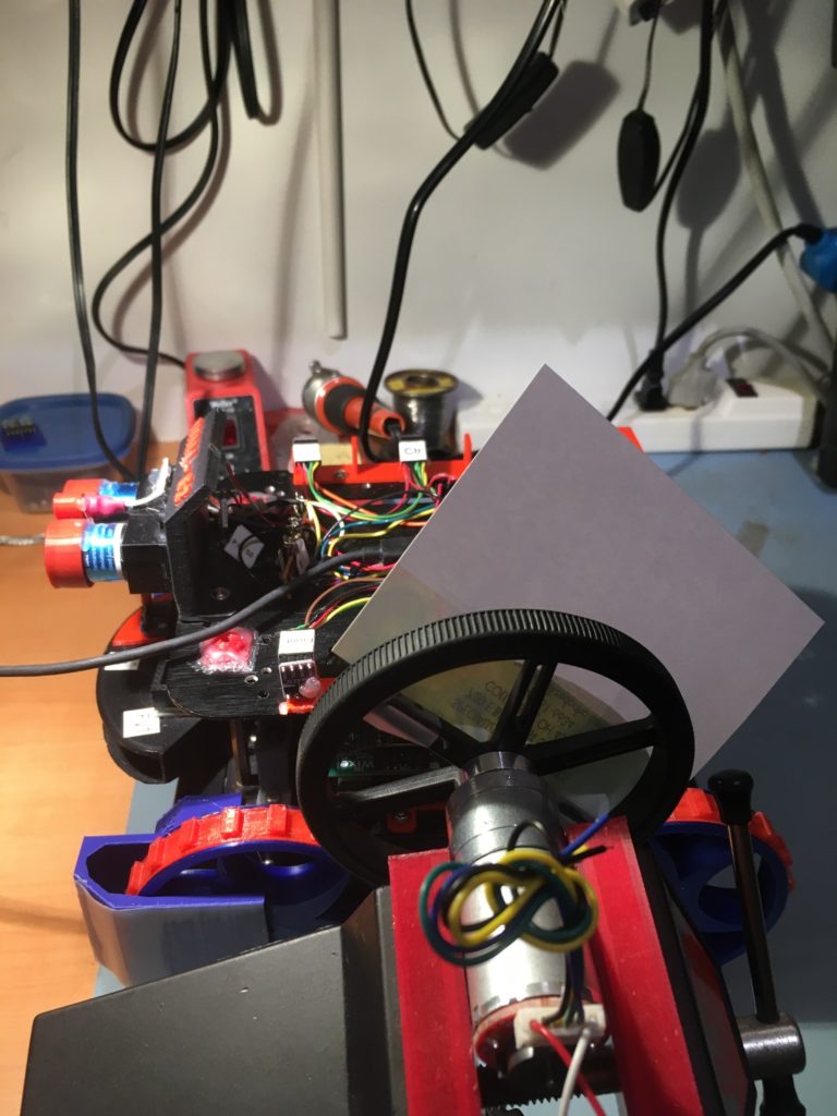
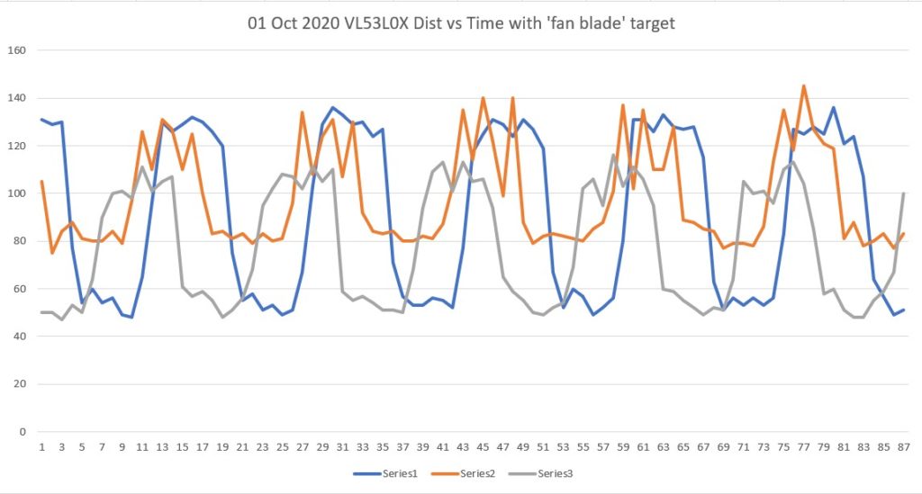
As a quick test, I rigged up a ‘fan blade’ (piece of paper taped to a old robot wheel on a motor) as shown, and then ran the program again with the motor spinning the ‘blade’ in front of the left-side sensor array (at about 100 RPM, I think). The plot shows that the sensor response is certainly fast enough to ‘see’ the rise and fall times on the ‘fan blade’.
|
1 2 3 4 5 6 7 8 9 10 11 12 13 14 15 16 17 18 19 20 21 22 23 24 25 26 27 28 29 30 31 32 33 34 35 36 37 38 39 40 41 42 43 44 45 46 47 48 49 50 51 52 53 54 55 56 57 58 59 60 61 62 63 64 65 66 67 68 69 70 71 72 73 74 75 76 77 78 79 80 81 82 83 84 85 86 87 |
86647 131 105 50 317 316 320 0.81 -0.03 86665 129 75 50 313 316 318 0.79 -0.05 86683 130 84 47 316 318 319 0.83 -0.03 86700 77 88 53 314 305 317 0.24 -0.03 86719 54 81 50 315 318 315 0.04 0.00 86737 60 80 64 313 307 328 -0.04 -0.15 86755 54 80 90 312 313 324 -0.36 -0.12 86773 56 84 100 316 315 323 -0.44 -0.07 86792 49 79 101 314 309 320 -0.52 -0.06 86809 48 97 98 316 314 321 -0.50 -0.05 86828 65 126 111 316 318 318 -0.46 -0.02 86846 96 110 101 317 306 321 -0.05 -0.04 86864 130 131 105 311 313 321 0.25 -0.10 86882 126 127 107 321 313 321 0.19 0.00 86901 129 110 61 314 313 307 0.68 0.07 86919 132 125 57 313 303 319 0.75 -0.06 86937 130 100 59 310 317 323 0.71 -0.13 86955 126 83 55 314 307 322 0.71 -0.08 86973 120 84 48 316 304 322 0.72 -0.06 86992 75 81 51 316 312 318 0.24 -0.02 87010 55 83 56 317 319 325 -0.01 -0.08 87028 58 79 68 313 322 319 -0.10 -0.06 87046 51 83 95 319 304 317 -0.44 0.02 87065 53 80 102 313 311 327 -0.49 -0.14 87083 49 81 108 313 303 323 -0.59 -0.10 87101 51 96 107 318 302 318 -0.56 0.00 87119 67 134 102 313 319 322 -0.35 -0.09 87137 103 108 111 309 314 319 -0.08 -0.10 87155 129 124 105 309 311 321 0.24 -0.12 87174 136 131 110 313 316 319 0.26 -0.06 87192 133 107 59 323 302 319 0.74 0.04 87210 129 130 55 312 299 315 0.74 -0.03 87228 130 92 57 312 315 323 0.73 -0.11 87247 124 84 54 307 315 323 0.70 -0.16 87265 127 83 51 305 317 322 0.76 -0.17 87283 71 84 51 313 303 319 0.20 -0.06 87301 57 80 50 316 317 320 0.07 -0.04 87319 53 80 68 317 307 318 -0.15 -0.01 87338 53 82 94 317 317 321 -0.41 -0.04 87356 56 81 109 310 315 318 -0.53 -0.08 87374 55 87 113 314 303 315 -0.58 -0.01 87392 52 103 101 309 314 325 -0.49 -0.16 87410 77 135 113 319 310 326 -0.36 -0.07 87428 117 114 105 318 310 322 0.12 -0.04 87447 125 140 106 314 307 323 0.19 -0.09 87465 131 122 94 314 312 326 0.37 -0.12 87483 129 99 65 314 318 320 0.64 -0.06 87501 124 140 59 313 314 325 0.65 -0.12 87520 131 88 55 312 317 323 0.76 -0.11 87538 127 79 50 313 308 321 0.77 -0.08 87556 119 82 49 318 306 322 0.70 -0.04 87574 67 83 52 310 312 319 0.15 -0.09 87592 52 82 54 310 310 322 -0.02 -0.12 87611 60 81 69 313 318 322 -0.09 -0.09 87629 57 80 102 317 298 317 -0.45 0.00 87647 49 85 106 309 303 317 -0.57 -0.08 87665 52 88 95 308 317 318 -0.43 -0.10 87684 56 101 116 313 313 318 -0.60 -0.05 87702 80 137 103 323 302 319 -0.23 0.04 87720 131 102 111 312 331 316 0.20 -0.04 87738 131 135 106 323 307 317 0.25 0.06 87756 126 110 95 310 303 316 0.31 -0.06 87774 133 110 60 315 309 324 0.73 -0.09 87793 128 128 59 314 306 321 0.69 -0.07 87811 127 89 55 317 310 321 0.72 -0.04 87829 128 88 52 320 323 323 0.76 -0.03 87847 115 85 49 315 316 320 0.66 -0.05 87865 63 84 52 315 324 323 0.11 -0.08 87884 51 77 51 313 319 321 0.00 -0.08 87902 56 79 64 306 307 320 -0.08 -0.14 87920 53 79 105 312 311 319 -0.52 -0.07 87938 56 78 100 313 319 317 -0.44 -0.04 87957 53 86 101 316 302 324 -0.48 -0.08 87975 56 113 96 313 302 321 -0.40 -0.08 87993 83 135 110 318 312 321 -0.27 -0.03 88011 127 118 113 307 313 322 0.14 -0.15 88029 125 145 104 318 325 323 0.21 -0.05 88047 128 127 85 315 314 324 0.43 -0.09 88066 125 121 58 319 297 311 0.67 0.08 88084 136 119 60 315 313 321 0.76 -0.06 88102 121 81 51 311 311 319 0.70 -0.08 88120 124 88 48 313 313 316 0.76 -0.03 88139 107 78 48 316 314 325 0.59 -0.09 88157 64 80 55 316 305 320 0.09 -0.04 88175 57 83 59 317 311 324 -0.02 -0.07 88193 49 77 67 318 310 315 -0.18 0.03 88212 51 83 100 312 301 327 -0.49 -0.15 |
03 October 2020 Update
With the above results in mind, I decided to try speeding up the ‘fan blade’ setup to see if I could find out how fast the VL53L0X sensor could go. I thought I should be able to use the shaft encoder setup on the back of the motor to acquire an accurate RPM reading and convert that into ‘milliseconds/blade’ to tell how short of an interval the VL53L0X could detect. As things often happen, determining motor RPM from encoder signals turned out to be a LOT harder than I thought. After a loooonnnng side-trip into geared-motor hell, I wound up more or less disregarding the encoder feature and modified the Teensy 3.5 ‘loop()’ code to produce a direct tachometer reading, as follows:
|
1 2 3 4 5 6 7 8 9 10 11 12 13 14 15 16 17 18 19 20 21 22 23 24 25 26 27 28 29 30 31 32 33 |
void loop() { //from Pololu forum post RF_Dist_mm = lidar_RF.readRangeContinuousMillimeters(); RC_Dist_mm = lidar_RC.readRangeContinuousMillimeters(); RR_Dist_mm = lidar_RR.readRangeContinuousMillimeters(); RightSteeringVal = (RF_Dist_mm - RR_Dist_mm) / 100.f; //rev 06/21/20 see PPalace post //from Pololu forum post LF_Dist_mm = lidar_LF.readRangeContinuousMillimeters(); LC_Dist_mm = lidar_LC.readRangeContinuousMillimeters(); LR_Dist_mm = lidar_LR.readRangeContinuousMillimeters(); LeftSteeringVal = (LF_Dist_mm - LR_Dist_mm) / 100.f; //rev 06/21/20 see PPalace post Serial.printf("%lu\t%d\t%d\t%d\t%d\t%d\t%d\t%2.2f\t%2.2f\n", millis(), LF_Dist_mm, LC_Dist_mm, LR_Dist_mm, RF_Dist_mm, RC_Dist_mm, RR_Dist_mm, LeftSteeringVal, RightSteeringVal); //10/03/20 produce digital 'tachometer' output using //left-front VL53L0X sensor if (LF_Dist_mm > 0 && LF_Dist_mm < LEFT_FRONT_TACH_THRESHOLD_MM) { digitalWriteFast(LEFT_FRONT_TACH_OUT_PIN, HIGH); } else { digitalWriteFast(LEFT_FRONT_TACH_OUT_PIN, LOW); } } |
This allowed me to directly monitor ‘effective’ RPM & obstruction frequency. So I set up the experiment using a ‘four blade fan’ as shown below, and monitored the obstruction detector output with my Hanmatek DSO
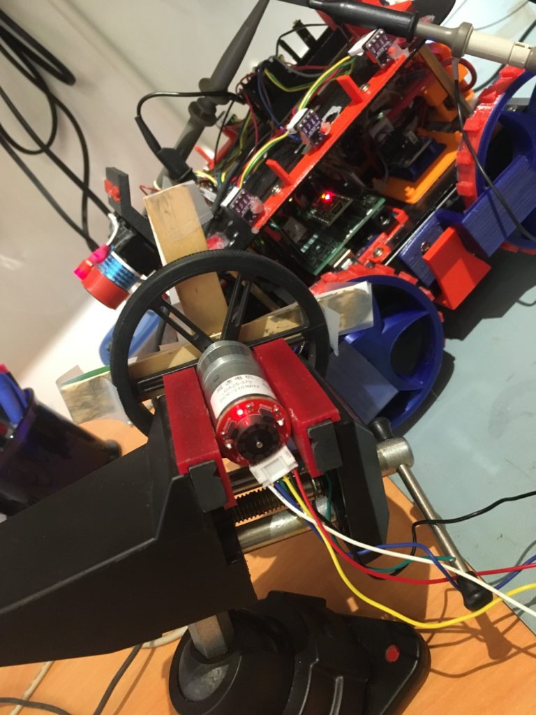
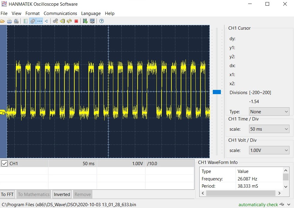
As can be seen from the DSO screenshot, the obstruction detection pulse frequency is about 26Hz, with a period of a little over 38 mSec. So it is clear that the VL53L0X running in continuous mode with a timing budget of 20 mSec can easily produce readings every 30 mSec or so.
04 October Update:
The next step was to see if the ‘VL53L0X fast/continuous’ code running on the Teensy VL53L0X sensor array manager would allow the main robot MCU to fetch distance readings faster. To do this, I uncommented the #define DISTANCES_ONLY //added 11/14/18 to just display distances in infinite loop line in my program to eliminate all code except a short loop displaying distances. Then I took measurements with my 4-blade ‘fan’ running in front of the left-front sensor. I ran the motor voltage up to the point where the Teensy’s blade sensor output was showing about a 20Hz blade rate, and got the following output from the main MCU ‘DISTANCES_ONLY’ loop.
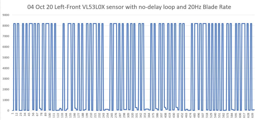
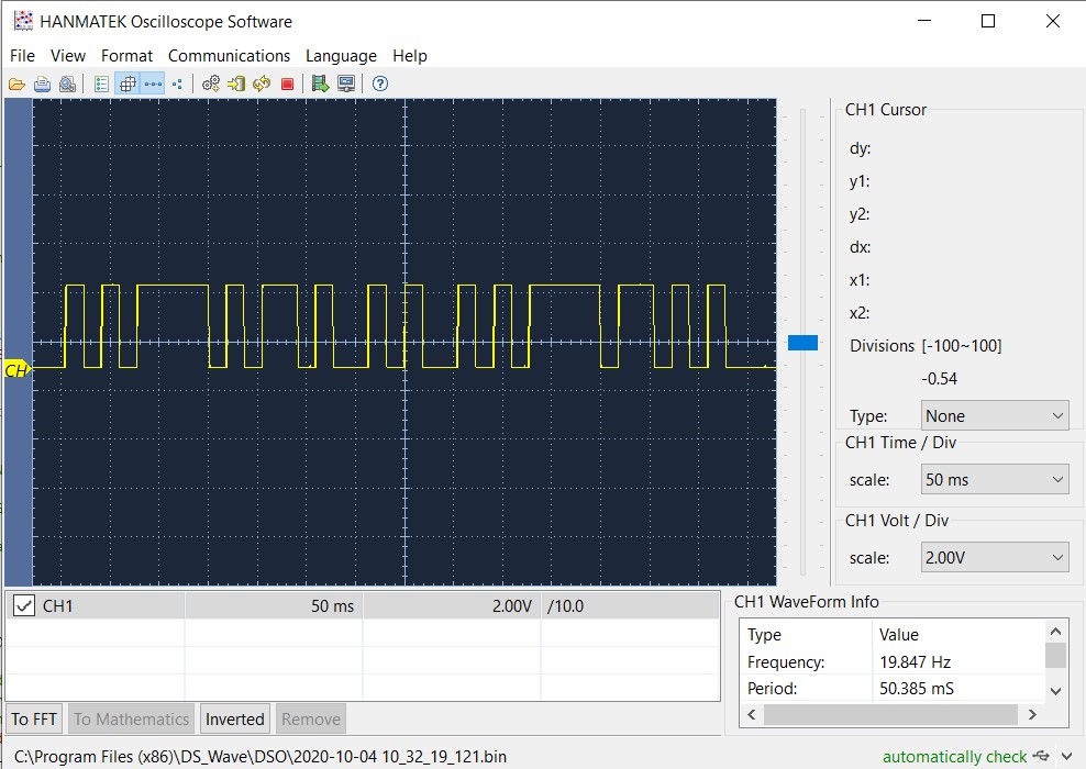
From the above, it is clear that the main MCU code can ‘see’ sensor output changes occurring at 20 Hz (50 mSec period). This should be fast enough to keep up with the physical movement of the robot during offset capture and wall-tracking activities.
In theory, I won’t have to do anything to the main MCU code to enjoy the faster response
Stay Tuned!
Frank
Pingback: Left Side Wall Tracking Success With VL53L0X Array | Paynter's Palace