posted 13 March 2020,
While updating my four wheel autonomous wall-following robot (aka Wall-E2), I ran into a roadblock when I couldn’t get my Teensy 3.2 IR demodulator/tracker module to communicate with the Mega 2560 main microcontroller over I2C. This worked fine when I last tested it, but now it seems to have taken a vacation. It’s been a while, and I have added some functionality since I originally installed and tested IR homing to the charging station, but it still should all work, right?
In any case, after trying (and failing) to get the I2C bus connection working, I thought I might try an alternate solution and just use SPI between the main controller (Mega 2560) and the IR homing controller (Teensy 3.2). This would have the advantage of making the Teensy independent of the I2C bus, and also give me the chance to play with a part of the Arduino ecosystem that I haven’t used before.
As usual, I started this process with a lot of Googling, and quickly ran across Australian Nick Gammon’s “SPI – Serial Peripheral Interface – for Arduino“ . This post was way more than I ever wanted to know about SPI, but it sure is complete!
Then I moved on to trying to get SPI working for myself. As noted above, my intended application is to transfer steering values from my IR detector/demodulator/homing module to the main Mega 2560 microcontroller. The Mega uses the steering data to adjust wheel speeds to home in on a charging station, so Wall-E2 can continue to roam our house autonomously.
It turns out that SPI between two Arduinos isn’t entirely straightforward, at least not at first. I went through a bunch of iterations, and even more passes through the available documentation. In the end though, I think I wrassled it into a reasonable facsimile of a working solution, as shown below. The program repeatedly transfers a fixed string (“Hello World!”) from the UNO (master) to the Mega 2560 (slave), and then transfers the string version of a float value (3.159) from the slave to the master.
The Circuit:
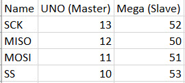
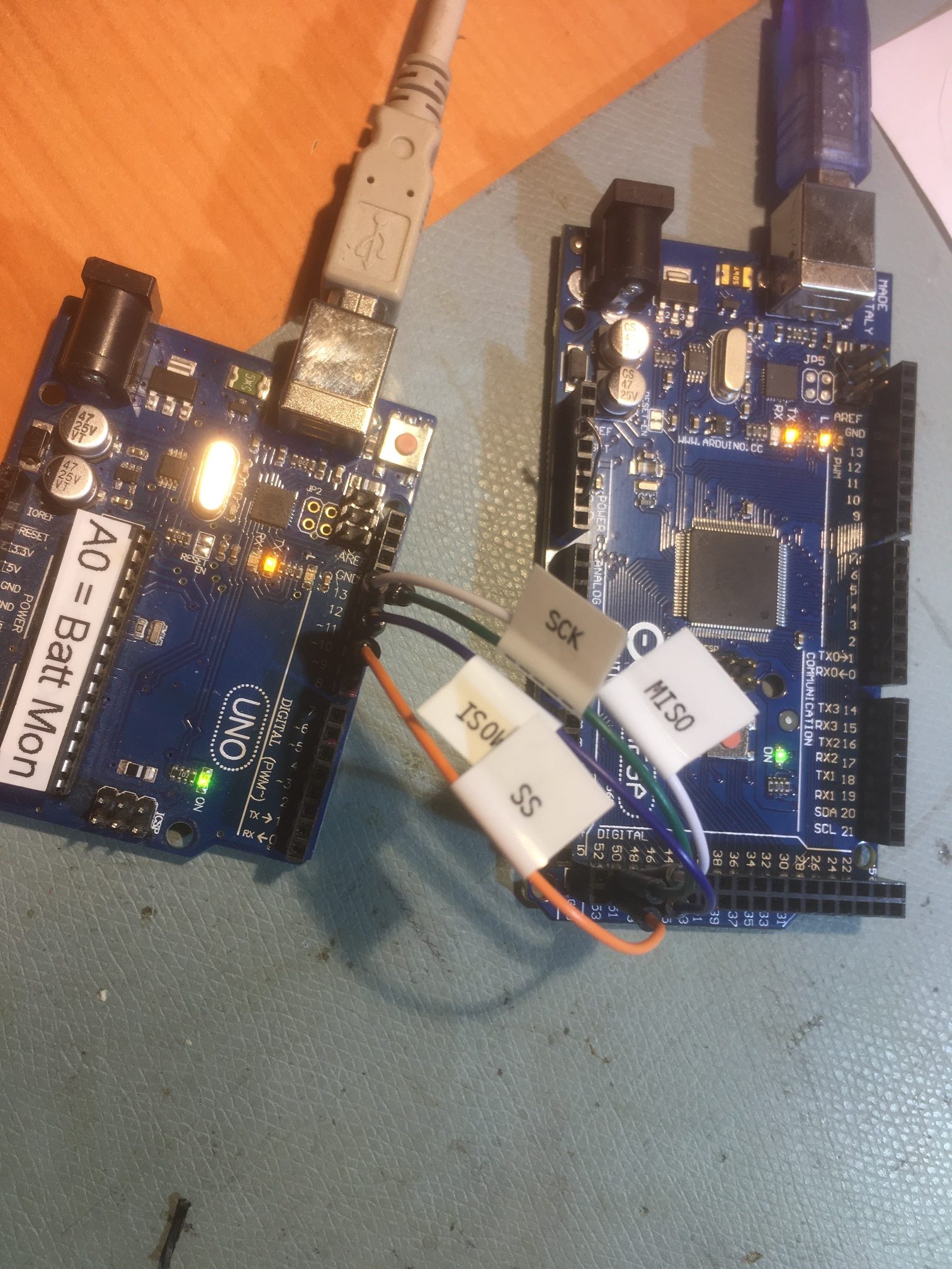
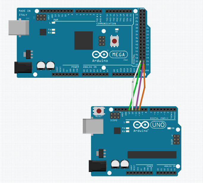
The circuit and layout is just about as basic as it gets. The UNO (master) connections are the default pinouts:


UNO (master) connected to Mega 2560 (slave) using default SPI pins on both ends

The Master:
|
1 2 3 4 5 6 7 8 9 10 11 12 13 14 15 16 17 18 19 20 21 22 23 24 25 26 27 28 29 30 31 32 33 34 35 36 37 38 39 40 41 42 43 44 45 46 47 48 49 50 51 52 53 54 55 56 57 58 59 60 61 62 63 64 65 66 67 68 69 70 71 72 73 74 75 76 77 78 79 80 81 82 83 84 85 86 87 88 89 90 91 92 |
/* Name: SPI_EX3_Master.ino Created: 3/13/2020 4:19:35 PM Author: FRANKNEWXPS15\Frank */ #include <SPI.h> #include "pins_arduino.h" #include <PrintEx.h> //allows printf-style printout syntax StreamEx mySerial = Serial; //added 03/18/18 for printf-style printing volatile byte rcvbyte = 0; char rcvbuf[100]; void setup(void) { Serial.begin(115200); // Put SCK, MOSI, SS pins into output mode // also put SCK, MOSI into LOW state, and SS into HIGH state. // Then put SPI hardware into Master mode and turn SPI on SPI.begin(); Serial.println("SPI Example Master"); memset(rcvbuf, 0, sizeof(rcvbuf)); } // end of setup void loop(void) { char c; // send test string Serial.println("Sending Test String"); //tell slave to get ready digitalWrite(SS, LOW); // SS is pin 10 delayMicroseconds(200); //give slave some time // send test string for (const char* p = "Hello, world!\n"; c = *p; p++) { mySerial.printf("Sending %x to Slave\n", c); SPI.transfer(c); delayMicroseconds(20); //required for arduino-arduino xfrs } //receive data from slave delay(500); //get float value from slave Serial.println("Receiving Data String\n"); int pos = 0; memset(rcvbuf, sizeof(rcvbuf), 0); c = 1; while (c != 0x0D) { c = SPI.transfer(0); mySerial.printf("got %x from Slave\n", c); rcvbuf[pos++] = c; delayMicroseconds(20); } //remove any non-numeric characters char buf2[20]; int buf2pos = 0; for (size_t i = 0; i < sizeof(rcvbuf); i++) { char p = rcvbuf[i]; // search for space if (p > 0x20 ) { buf2[buf2pos++] = p; } buf2[buf2pos] = 0; } rcvbuf[pos] = 0; //add NULL to terminate string if (pos > 0) { mySerial.printf("received %s from slave\n", buf2); } // tell slave to get ready for next data transfer digitalWrite(SS, HIGH); delay(1000); // 1 seconds delay } // end of loop |
The Slave:
|
1 2 3 4 5 6 7 8 9 10 11 12 13 14 15 16 17 18 19 20 21 22 23 24 25 26 27 28 29 30 31 32 33 34 35 36 37 38 39 40 41 42 43 44 45 46 47 48 49 50 51 52 53 54 55 56 57 58 59 60 61 62 63 64 65 66 67 68 69 70 71 72 73 74 75 76 77 78 79 80 81 82 83 84 85 86 87 88 89 90 91 92 93 94 95 96 97 98 99 100 101 102 103 |
/* Name: SPI_EX3_Slave.ino Created: 3/13/2020 4:21:43 PM Author: Frank */ #include "pins_arduino.h" #include <SPI.h> #include <PrintEx.h> //allows printf-style printout syntax StreamEx mySerial = Serial; //added 03/18/18 for printf-style printing char buf[100]; char val[20]; volatile byte rcv_pos; volatile byte xmt_pos; volatile boolean process_it; volatile boolean bReceivingString; void setup(void) { Serial.begin(115200); // debugging mySerial.printf("SPI Example Slave\n"); // have to send on master in, *slave out* pinMode(MISO, OUTPUT); pinMode(PIN_SPI_SS, INPUT_PULLUP); //SS is INPUT for slave device // turn on SPI in slave mode SPCR |= _BV(SPE); // turn on interrupts SPCR |= _BV(SPIE); rcv_pos = 0; process_it = false; //use dstrtof to produce string version of float value float x = 3.14159; memset(val, 0x0D, sizeof(val)); dtostrf(x, 7, 5, val); mySerial.printf("string representation of %2.5f is %s\n", x, val); for (size_t i = 0; i < sizeof(val) - 1; i++) { mySerial.printf("%x", val[i]); } mySerial.printf("%x\n", val[sizeof(val) - 1]); xmt_pos = 0; } // end of setup // SPI interrupt routine ISR(SPI_STC_vect) { if (bReceivingString) { byte c = SPDR; // add to buffer if room if (rcv_pos < sizeof buf) { buf[rcv_pos++] = c; //newline means time to process buffer if (c == '\n') process_it = true; } // end of room available } else { SPDR = val[xmt_pos]; xmt_pos++; } } // main loop - wait for flag set in interrupt routine void loop(void) { if (process_it) { mySerial.printf("In process_it with rcv_pos = %d\n", rcv_pos); buf[rcv_pos] = 0; mySerial.printf("Received %s from Master\n", buf); rcv_pos = 0; process_it = false; bReceivingString = false; } // end of flag set if (digitalRead(PIN_SPI_SS) == HIGH) { xmt_pos = 0; //get ready for next iteration SPDR = 0; bReceivingString = true; process_it = false; } } // end of loop |
The above configuration produced the following output:
Master:
|
1 2 3 4 5 6 7 8 9 10 11 12 13 14 15 16 17 18 19 20 21 22 23 24 25 26 27 28 29 30 31 |
Opening port Port open SPI Example Master Sending Test String Sending 48 to Slave Sending 65 to Slave Sending 6C to Slave Sending 6C to Slave Sending 6F to Slave Sending 2C to Slave Sending 20 to Slave Sending 77 to Slave Sending 6F to Slave Sending 72 to Slave Sending 6C to Slave Sending 64 to Slave Sending 21 to Slave Sending A to Slave Receiving Data String got A from Slave got 33 from Slave got 2E from Slave got 31 from Slave got 34 from Slave got 31 from Slave got 35 from Slave got 39 from Slave got 0 from Slave got D from Slave received 3.14159 from slave |
Slave:
|
1 2 3 4 5 6 7 8 9 10 11 12 13 14 15 16 17 18 19 20 21 22 23 24 25 |
Opening port Port open SPI Example Slave string representation of 3.14159 is 3.14159 332E31343135390DDDDDDDDDDDD In process_it with rcv_pos = 14 Received Hello, world! from Master In process_it with rcv_pos = 14 Received Hello, world! from Master In process_it with rcv_pos = 14 Received Hello, world! from Master In process_it with rcv_pos = 14 Received Hello, world! from Master In process_it with rcv_pos = 14 Received Hello, world! from Master In process_it with rcv_pos = 14 Received Hello, world! from Master Port closed |
Now that I’ve had my fun and games with SPI, I’m still not at all sure I want to use it to connect the Mega to the Teensy IR Demodulator/Homing module. While it is almost certain to work (eventually), it has some drawbacks
- It requires 4 additional wires
- It requires that I add an ISR and other code to the Teensy module, and companion code to the Mega
- More things to go wrong.
So, I think I’ll try again to get the original I2C based code working, as it worked before, so it should work again. If I can’t get it working after another good try, I’ll go with door #2 (SPI)
Stay tuned!
Frank
thanks for providing this example. Your code line delay(500) unfortunately makes the SPI as slow as Serial comms.
one of the main reasons for using SPI is its very low execution time.
You are welcome. When I did this I was just playing around, trying to learn about SPI. That delay (along with the print statements) can probably be removed – have you tried this?
Frank