/*
Name: Teensy_I2C_Sniffer_V6.ino
Created: 1/4/2020 8:40:20 AM
Author: FRANKNEWXPS15\Frank
This is a port of my Excel VBA code into Arduino/Teensy C++ language.
It parses the exact same sample data as the Excel program, so it should
produce the exact same I2C sequences.
The captured sample data to be parsed is held in the 'simdata' array.
The original VBA code is saved in 'ExcelVBACode.txt'
*/
/* 'Notes:
A typical I2C sentence when communicating with a MPU6050 IMU module goes like:
"I2C(68) wrote 1 byte to 75 - C0 Done."
"I2C(68) wrote 3 bytes to 72 - C0 0C 10 Done."
"I2C(68) read 5 bytes from 6A - C0 0C 10 14 03 Done."
To form a sentence, we need:
Device addr: 68 in the above examples
Read/Write direction
To/From register address: 75, 72 and 6A in the above examples
Data: C0, C0 0C 10, and C0 0C 10 14 03 in the above examples
number of bytes written/read: 1,3 & 5 in the above examples
Each I2C communication proceeds as follows (assuming a START from an IDLE condition):
A START or RESTART condition, denoted by SDA & SCL HIGH, followed by SDA LOW, SCL HIGH
A 7-bit device address, MSB first (0x8/0xC = 1, 0x0/0x4 = 0)
A R/W bit (0x8/0xC = read, 0x0/0x4 = write)
An ACK bit (0x8/0xC = NAK, 0x0/0x4 = ACK)
If the bus direction is WRITE, then
A register address for read/write
zero or more additional data bytes
Else (the bus direction is READ)
One or more additional data bytes
Endif
*/
/*
This version adds tonton81's circular buffer class (https://github.com/tonton81/Circular_Buffer)
to simulate real-time processing and display of I2C bus activity. The sample data is loaded into
a FIFO by an ISR triggered every microsecond by a timer, and then the processing code pulls it out
and parses it as fast as possible. If this works, then the next version will eliminate the sample
data and connect to a live I2C bus.
*/
#include <TimerOne.h> //needed for ISR
#include "circular_buffer.h"
Circular_Buffer<uint8_t, 2048> cb_trans; //holds transition values from ISR
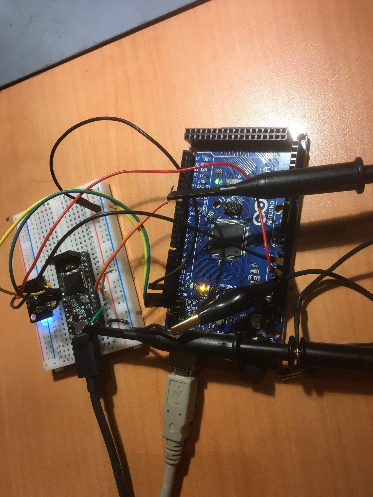
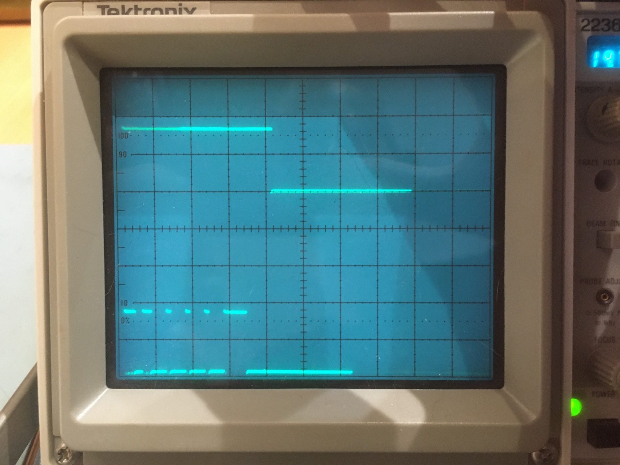
#define MONITOR_OUT1 2 //so can monitor ISR activity with O'scope
#define MONITOR_OUT2 3 //so can monitor ISR activity with O'scope
const int SIM_DATA_ARRAY_SIZE = 928;
byte simdata[SIM_DATA_ARRAY_SIZE] =
{
0xc, 0x4, 0x8, 0xc, 0x8, 0xc, 0x0, 0x4, 0x8, 0xc, 0x0,
0x4, 0x0, 0x4, 0x0, 0x4, 0x0, 0x4, 0x0, 0x4, 0x0, 0x4, 0x8, 0xc, 0x8, 0xc,
0x8, 0xc, 0x0, 0x4, 0x8, 0xc, 0x0, 0x4, 0x8, 0xc, 0x0, 0x4, 0x0, 0x4, 0xc,
0x4, 0x8, 0xc, 0x8, 0xc, 0x0, 0x4, 0x8, 0xc, 0x0, 0x4, 0x0, 0x4, 0x0, 0x4,
0x8, 0xc, 0x0, 0x4, 0x0, 0x4, 0x8, 0xc, 0x8, 0xc, 0x0, 0x4, 0x8, 0xc, 0x0,
0x4, 0x0, 0x4, 0x0, 0x4, 0x8, 0xc, 0x0, 0x4, 0xc, 0x4, 0x8, 0xc, 0x8, 0xc,
0x0, 0x4, 0x8, 0xc, 0x0, 0x4, 0x0, 0x4, 0x0, 0x4, 0x0, 0x4, 0x0, 0x4, 0x0,
0x4, 0x8, 0xc, 0x8, 0xc, 0x0, 0x4, 0x8, 0xc, 0x0, 0x4, 0x8, 0xc, 0x0, 0x4,
0x0, 0x4, 0x0, 0x4, 0xc, 0x4, 0x8, 0xc, 0x8, 0xc, 0x0, 0x4, 0x8, 0xc, 0x0,
0x4, 0x0, 0x4, 0x0, 0x4, 0x8, 0xc, 0x0, 0x4, 0x8, 0xc, 0x8, 0xc, 0x0, 0x4,
0x0, 0x4, 0x0, 0x4, 0x0, 0x4, 0x0, 0x4, 0x0, 0x4, 0x8, 0xc, 0x0, 0x4, 0xc,
0x4, 0x8, 0xc, 0x8, 0xc, 0x0, 0x4, 0x8, 0xc, 0x0, 0x4, 0x0, 0x4, 0x0, 0x4,
0x0, 0x4, 0x0, 0x4, 0x0, 0x4, 0x8, 0xc, 0x8, 0xc, 0x0, 0x4, 0x8, 0xc, 0x0,
0x4, 0x8, 0xc, 0x0, 0x4, 0x0, 0x4, 0x8, 0xc, 0x8, 0xc, 0x0, 0x4, 0x0, 0x4,
0x0, 0x4, 0x8, 0xc, 0x0, 0x4, 0x0, 0x4, 0x0, 0x4, 0x0, 0x4, 0xc, 0x4, 0x8,
0xc, 0x8, 0xc, 0x0, 0x4, 0x8, 0xc, 0x0, 0x4, 0x0, 0x4, 0x0, 0x4, 0x0, 0x4,
0x0, 0x4, 0x0, 0x4, 0x8, 0xc, 0x8, 0xc, 0x8, 0xc, 0x0, 0x4, 0x0, 0x4, 0x8,
0xc, 0x0, 0x4, 0x0, 0x4, 0x0, 0x4, 0xc, 0x4, 0x8, 0xc, 0x8, 0xc, 0x0, 0x4,
0x8, 0xc, 0x0, 0x4, 0x0, 0x4, 0x0, 0x4, 0x8, 0xc, 0x0, 0x4, 0x0, 0x4, 0x0,
0x4, 0x0, 0x4, 0x0, 0x4, 0x0, 0x4, 0x0, 0x4, 0x0, 0x4, 0x0, 0x4, 0x0, 0x4,
0x0, 0x4, 0x0, 0x4, 0x0, 0x4, 0x8, 0xc, 0x8, 0xc, 0x8, 0xc, 0x0, 0x4, 0x0,
0x4, 0x8, 0xc, 0x0, 0x4, 0xc, 0x4, 0x8, 0xc, 0x8, 0xc, 0x0, 0x4, 0x8, 0xc,
0x0, 0x4, 0x0, 0x4, 0x0, 0x4, 0x0, 0x4, 0x0, 0x4, 0x0, 0x4, 0x8, 0xc, 0x8,
0xc, 0x8, 0xc, 0x0, 0x4, 0x0, 0x4, 0x8, 0xc, 0x0, 0x4, 0x0, 0x4, 0x0, 0x4,
0xc, 0x4, 0x8, 0xc, 0x8, 0xc, 0x0, 0x4, 0x8, 0xc, 0x0, 0x4, 0x0, 0x4, 0x0,
0x4, 0x8, 0xc, 0x0, 0x4, 0x0, 0x4, 0x0, 0x4, 0x0, 0x4, 0x0, 0x4, 0x0, 0x4,
0x0, 0x4, 0x0, 0x4, 0x0, 0x4, 0x0, 0x4, 0x0, 0x4, 0x0, 0x4, 0x8, 0xc, 0x8,
0xc, 0x8, 0xc, 0x0, 0x4, 0x0, 0x4, 0x0, 0x4, 0x8, 0xc, 0x0, 0x4, 0xc, 0x4,
0x8, 0xc, 0x8, 0xc, 0x0, 0x4, 0x8, 0xc, 0x0, 0x4, 0x0, 0x4, 0x0, 0x4, 0x0,
0x4, 0x0, 0x4, 0x0, 0x4, 0x8, 0xc, 0x8, 0xc, 0x8, 0xc, 0x0, 0x4, 0x0, 0x4,
0x8, 0xc, 0x0, 0x4, 0x0, 0x4, 0x0, 0x4, 0xc, 0x4, 0x8, 0xc, 0x8, 0xc, 0x0,
0x4, 0x8, 0xc, 0x0, 0x4, 0x0, 0x4, 0x0, 0x4, 0x8, 0xc, 0x0, 0x4, 0x0, 0x4,
0x0, 0x4, 0x0, 0x4, 0x0, 0x4, 0x0, 0x4, 0x0, 0x4, 0x0, 0x4, 0x0, 0x4, 0x0,
0x4, 0x0, 0x4, 0x8, 0xc, 0x0, 0x4, 0x8, 0xc, 0x0, 0x4, 0x8, 0xc, 0x0, 0x4,
0x0, 0x4, 0x8, 0xc, 0x0, 0x4, 0xc, 0x4, 0x8, 0xc, 0x8, 0xc, 0x0, 0x4, 0x8,
0xc, 0x0, 0x4, 0x0, 0x4, 0x0, 0x4, 0x0, 0x4, 0x0, 0x4, 0x0, 0x4, 0x8, 0xc,
0x8, 0xc, 0x8, 0xc, 0x0, 0x4, 0x0, 0x4, 0x8, 0xc, 0x0, 0x4, 0x0, 0x4, 0x0,
0x4, 0xc, 0x4, 0x8, 0xc, 0x8, 0xc, 0x0, 0x4, 0x8, 0xc, 0x0, 0x4, 0x0, 0x4,
0x0, 0x4, 0x8, 0xc, 0x0, 0x4, 0x0, 0x4, 0x0, 0x4, 0x0, 0x4, 0x0, 0x4, 0x0,
0x4, 0x0, 0x4, 0x0, 0x4, 0x0, 0x4, 0x0, 0x4, 0x0, 0x4, 0x8, 0xc, 0x8, 0xc,
0x8, 0xc, 0x0, 0x4, 0x0, 0x4, 0x0, 0x4, 0x0, 0x4, 0x8, 0xc, 0x0, 0x4, 0xc,
0x4, 0x8, 0xc, 0x8, 0xc, 0x0, 0x4, 0x8, 0xc, 0x0, 0x4, 0x0, 0x4, 0x0, 0x4,
0x0, 0x4, 0x0, 0x4, 0x0, 0x4, 0x8, 0xc, 0x8, 0xc, 0x8, 0xc, 0x0, 0x4, 0x0,
0x4, 0x8, 0xc, 0x0, 0x4, 0x0, 0x4, 0x0, 0x4, 0xc, 0x4, 0x8, 0xc, 0x8, 0xc,
0x0, 0x4, 0x8, 0xc, 0x0, 0x4, 0x0, 0x4, 0x0, 0x4, 0x8, 0xc, 0x0, 0x4, 0x0,
0x4, 0x0, 0x4, 0x0, 0x4, 0x0, 0x4, 0x0, 0x4, 0x0, 0x4, 0x0, 0x4, 0x0, 0x4,
0x0, 0x4, 0x8, 0xc, 0x0, 0x4, 0x0, 0x4, 0x0, 0x4, 0x8, 0xc, 0x8, 0xc, 0x0,
0x4, 0x0, 0x4, 0x8, 0xc, 0x0, 0x4, 0xc, 0x4, 0x8, 0xc, 0x8, 0xc, 0x0, 0x4,
0x8, 0xc, 0x0, 0x4, 0x0, 0x4, 0x0, 0x4, 0x0, 0x4, 0x0, 0x4, 0x0, 0x4, 0x8,
0xc, 0x8, 0xc, 0x8, 0xc, 0x0, 0x4, 0x0, 0x4, 0x8, 0xc, 0x0, 0x4, 0x0, 0x4,
0x0, 0x4, 0xc, 0x4, 0x8, 0xc, 0x8, 0xc, 0x0, 0x4, 0x8, 0xc, 0x0, 0x4, 0x0,
0x4, 0x0, 0x4, 0x8, 0xc, 0x0, 0x4, 0x0, 0x4, 0x0, 0x4, 0x0, 0x4, 0x0, 0x4,
0x0, 0x4, 0x0, 0x4, 0x0, 0x4, 0x0, 0x4, 0x0, 0x4, 0x8, 0xc, 0x8, 0xc, 0x0,
0x4, 0x0, 0x4, 0x0, 0x4, 0x8, 0xc, 0x0, 0x4, 0x0, 0x4, 0x8, 0xc, 0x0, 0x4,
0xc, 0x4, 0x8, 0xc, 0x8, 0xc, 0x0, 0x4, 0x8, 0xc, 0x0, 0x4, 0x0, 0x4, 0x0,
0x4, 0x0, 0x4, 0x0, 0x4, 0x0, 0x4, 0x8, 0xc, 0x8, 0xc, 0x8, 0xc, 0x0, 0x4,
0x0, 0x4, 0x8, 0xc, 0x0, 0x4, 0x0, 0x4, 0x0, 0x4, 0xc, 0x4, 0x8, 0xc, 0x8,
0xc, 0x0, 0x4, 0x8, 0xc, 0x0, 0x4, 0x0, 0x4, 0x0, 0x4, 0x8, 0xc, 0x0, 0x4,
0x0, 0x4, 0x0, 0x4, 0x0, 0x4, 0x0, 0x4, 0x0, 0x4, 0x0, 0x4, 0x0, 0x4, 0x0,
0x4, 0x0, 0x4, 0x8, 0xc, 0x8, 0xc, 0x8, 0xc, 0x0, 0x4, 0x0, 0x4, 0x0, 0x4,
0x0, 0x4, 0x0, 0x4, 0x8, 0xc, 0x0, 0x4, 0xc, 0x4, 0x8, 0xc, 0x8, 0xc, 0x0,
0x4, 0x8, 0xc, 0x0, 0x4, 0x0, 0x4, 0x0, 0x4, 0x0, 0x4, 0x0, 0x4, 0x0, 0x4,
0x8, 0xc
};
//#define PARSE_LOOP_DEBUG
//#define GET_8BIT_DATABYTE_DEBUG
const int BUFFER_CHECK_INTERVAL_MSEC = 200;
//const int BUFFER_CHECK_INTERVAL_MSEC = 5;
#pragma region PROCESSING_VARIABLES
uint8_t devAddr;
uint8_t regAddr;
//added for bus direction labels
enum BUSDIR
{
WRITE,
READ,
UNKNOWN = -1
} RWDir;
BUSDIR BusDir = BUSDIR::UNKNOWN;
int ACKNAKFlag; //can be negative
uint8_t databyte_array[2048]; //holds multiple databytes for later output sentence construction
uint16_t databyte_idx = 0; //index into databyte_array
uint16_t numbytes = 0; //number of data bytes extracted from data stream
uint8_t killbuff[2]; //used to consume start/stop bytes
#pragma endregion ProcVars
#pragma region ISR_VARS
uint16_t write_index = 0;
uint16_t read_index = 0;
uint8_t current_portb = 0xFF;
uint8_t last_portb = 0xFF;
bool bBufferFull = false;
elapsedMillis mSecSinceLastBufferCheck;
#pragma endregion ISRVars
int DecodeAndPrintFIFOContents(Circular_Buffer<uint8_t, 2048>& cb); //need forward reference here
//-------------------------------------------------------------------------------
//-------------------------------- ISR ------------------------------------
//-------------------------------------------------------------------------------
//01/04/2020 modified to 'capture' data from simdata[]
void capture_data(void)
{
if (!bBufferFull) //for debug - writes only one set of data to FIFO
{
last_portb = current_portb;
current_portb = simdata[read_index]; //pull one transition value from simdata
read_index++;
if (last_portb != current_portb && !bBufferFull)
{
cb_trans.write(current_portb); //add current transition value to FIFO
digitalWriteFast(MONITOR_OUT1, !digitalReadFast(MONITOR_OUT1));
}
//pause writing to cb_trans circular buffer
if (read_index >= SIM_DATA_ARRAY_SIZE)
{
bBufferFull = true;
read_index = 0;
digitalWriteFast(MONITOR_OUT1, LOW);
}
}
}
void setup()
{
Serial.begin(1); //rate value ignored
unsigned long now = millis();
int idx = 0;
while (!Serial && (millis() - now) < 3000)
{
delay(500);
idx++;
}
Serial.printf("Serial available after %lu mSec\n", millis() - now);
pinMode(MONITOR_OUT1, OUTPUT);
pinMode(MONITOR_OUT2, OUTPUT);
pinMode(LED_BUILTIN, OUTPUT);
Timer1.initialize(1); // run every mico second
Timer1.attachInterrupt(capture_data);
mSecSinceLastBufferCheck = 0;
}
void loop()
{
if (mSecSinceLastBufferCheck > BUFFER_CHECK_INTERVAL_MSEC)
{
Serial.printf("%lu: cb_trans contains = %d elements\n", millis(), cb_trans.size());
mSecSinceLastBufferCheck -= BUFFER_CHECK_INTERVAL_MSEC;
DecodeAndPrintFIFOContents(cb_trans); //decode and print everything captured so far
Serial.printf("%lu: cb_trans contains = %d elements\n", millis(), cb_trans.size());
//cb_trans.clear();
read_index = 0;
bBufferFull = false;
digitalWriteFast(MONITOR_OUT2, !digitalReadFast(MONITOR_OUT2));
while (true)
{
}
}
}
void PrintNextFIFOBytes(Circular_Buffer<uint8_t, 2048>& cb, uint8_t numbytes)
{
Serial.printf("Next %d FIFO Bytes: ", numbytes);
for (uint8_t i = 0; i < numbytes-1; i++)
{
Serial.printf("%x,", cb.peek(i));
}
Serial.printf("%x\n", cb.peek(numbytes-1));
}
bool IsStart(Circular_Buffer<uint8_t, 2048>& cb)
{
bool result = false;
uint8_t data[2]; data[0] = data[1] = 0;
data[0] = cb.peek(0);
data[1] = cb.peek(1);
if (data[0] == 0xC && data[1] == 0x4)
{
//Serial.printf("Start detected at size = %d, data idx = %d\n", cb.size(), SIM_DATA_ARRAY_SIZE - cb.size());
result = true;
}
return result;
}
bool IsStop(Circular_Buffer<uint8_t, 2048>& cb)
{
bool result = false;
uint8_t data[2];
cb.peekBytes(data, 2);
if (data[0] == 0x4 && data[1] == 0xC)
{
//cb.readBytes(data, 2); //consume these bytes
result = true;
}
return result;
}
uint8_t Get7BitDeviceAddr(Circular_Buffer<uint8_t, 2048>& cb)
{
//Purpose: Construct a 7-bit address starting from next FIFO element
//Inputs:
// cb = reference to cb_trans FIFO
//Outputs:
// returns the address as an 8-bit value with the MSB = 0, or 0x0 if unsuccessful
// the 14 transitions associated with the 7-bit address removed from FIFO
//Plan:
// Step1: Convert a pair of FIFO elements into a 0 or 1
// Step2: Add the appropriate value to an ongoing sum
// Step3: return the total.
//Notes:
// A '0' is coded as a 0x0 followed by a 0x4
// A '1' is coded as a 0x8 followed by a 0xC
uint8_t devAddr = 0x0; //failure return value
//devAddr is exactly 7 bits long, so 8 bits with MSB = 0
uint8_t data[2]; //holds one transition pair
for (size_t i = 0; i < 7; i++)
{
cb.readBytes(data, 2);
//data[0] = cb.read();
//data[1] = cb.read();
//Serial.printf("data[0] = %x, data[1] = %x\n", data[0], data[1]);
if (data[0] == 0x8 && data[1] == 0xC)
{
//Serial.printf("Get7BitDeviceAddr: '1' found at i = %d, adding %x to devAddr to get %x\n",
//i, 1 << (7 - i), devAddr + (1 << (7 - i)));
devAddr += (1 << (7 - i)); //add 2^(7-i) to sum
}
}
devAddr = devAddr >> 1; //divide result by 2 to get 7-bit addr from 8 bits
return devAddr;
}
int GetReadWriteFlag(Circular_Buffer<uint8_t, 2048>& cb)
{
//Purpose: decode R/W byte pair
//Inputs:
// cb = reference to cb_trans FIFO
//Outputs:
// readidx = if successful, points to next byte pair in simdata
// returns 1 for Read (0x8/0xC), 0 for Write (0x0/0x4), -1 for failure
//Notes:
//
int result = 0;
uint8_t data[2];
data[0] = cb.read();
data[1] = cb.read();
//Serial.printf("data[0] = %x, data[1] = %x\n", data[0], data[1]);
if (data[0] == 0x8 && data[1] == 0xC)
{
result = 1; //read detected
}
//else if (simdata[readidx] == 0x0 && simdata[readidx + 1] == 0x4)
else if (data[0] == 0x0 && data[1] == 0x4)
{
result = 0; //write detected
}
else
{
result = -1; //failed to detect read or write
}
return result;
}
int GetACKNAKFlag(Circular_Buffer<uint8_t, 2048>& cb)
{
//Purpose: decode ACK/NAK byte pair
//Inputs:
// cb = reference to cb_trans circular buffer holding transition values
//Outputs:
// returns 1 for NAK (0x8/0xC), 0 for ACK (0x0/0x4), -1 for failure
//Notes:
// this code is identical to the code for GetReadWriteFlag, so use it instead
return GetReadWriteFlag(cb_trans);
}
int Get8BitDataByte(Circular_Buffer<uint8_t, 2048>& cb)
{
//Purpose: Construct a 8-bit data byte starting from dataidx
//Inputs:
// cb = reference to cb_trans circular buffer holding transition values
//Outputs:
// returns the address as an 8-bit value, or -1 if unsuccessful
// dataidx = pointer to next simdata entry
//Plan:
// Step1: Convert a pair of simdata entries into a 0 or 1
// Step2: Add the appropriate value to an ongoing sum
// Step3: return the total.
//Notes:
// A '0' is coded as a 0x0 followed by a 0x4
// A '1' is coded as a 0x8 followed by a 0xC
// 12/29/19 - changed return val to int, so can return -1 when a 'short byte' is detected
int dataval = 0x0;
int numbits = 0;
uint8_t data[2]{ 0x0,0x0 }; //holds one transition pair
////DEBUG!!
// Serial.printf("Get8BitDataByte top: data[0] = %x,data[1] = %x, size = %d, idx = %d\n",
// data[0], data[1], cb.size(), SIM_DATA_ARRAY_SIZE - cb.size());
// PrintNextFIFOBytes(cb, 20);
////DEBUG!!
//8 bits with MSB = 0
for (size_t i = 0; i < 8; i++)
{
data[0] = cb.peek(0); data[1] = cb.peek(1);
//Serial.printf("data[0] = %x, data[1] = %x\n", data[0], data[1]);
if (data[0] == 0x0 && data[1] == 0x4)
{
cb.readBytes(data, 2);// now consume the bytes
numbits++;
}
else if (data[0] == 0x8 && data[1] == 0xC)
{
#ifdef GET_8BIT_DATABYTE_DEBUG
Serial.printf("Get8BitDataByte: '1' found at i = %d, adding %x to devAddr to get %x\n",
i, 1 << (7 - i), dataval + (1 << (7 - i)));
#endif
cb.readBytes(data, 2);// now consume the bytes
dataval += (1 << (7 - i)); //add 2^(8-i) to sum
numbits++;
}
else //not a 1 or 0 - get me outa here!
{
break;
}
}
////DEBUG!!
// Serial.printf("Get8BitDataByte bottom: numbits = %d, data[0] = %x,data[1] = %x, size = %d, idx = %d\n",
// numbits, data[0], data[1], cb.size(), SIM_DATA_ARRAY_SIZE - cb.size());
// PrintNextFIFOBytes(cb, 20);
////DEBUG!!
if (numbits != 8)
{
dataval = -1; //error return value
}
return dataval;
}
int GetDataBytes(Circular_Buffer<uint8_t, 2048>& cb, uint8_t* databytes)
{
//Notes:
// 01/01/2020: removed databyteidx from sig - always starts at zero
uint16_t numbytes = 0;
uint16_t databyte_idx = 0;
bool StartFlag = false;
bool StopFlag = false;
int dataval;
do
{
dataval = Get8BitDataByte(cb);
////DEBUG!!
// Serial.printf("GetDataBytes() just after Get8BitDataByte(): datval = %x, size = %d, idx = %d\n",
// dataval, cb.size(), SIM_DATA_ARRAY_SIZE-cb.size());
// PrintNextFIFOBytes(cb, 10);
////DEBUG!!
//watch out for 'short byte' reads
if (dataval >= 0)
{
uint8_t databyte = (uint8_t)dataval;
databyte_array[databyte_idx] = databyte;
databyte_idx++;
numbytes++;
ACKNAKFlag = GetACKNAKFlag(cb_trans); //01/05/20 moved inside 'good byte' block
}
//ACKNAKFlag = GetACKNAKFlag(cb_trans);
////DEBUG!!
// Serial.printf("GetDataBytes() just after GetACKNAKFlag(): ACKNAK = %d, size = %d, idx = %d\n",
// ACKNAKFlag, cb.size(), SIM_DATA_ARRAY_SIZE-cb.size());
// PrintNextFIFOBytes(cb, 10);
////DEBUG!!
StartFlag = IsStart(cb_trans);
////DEBUG!!
// Serial.printf("GetDataBytes() just after IsStart(): StartFlag = %d, size = %d, idx = %d\n",
// StartFlag, cb.size(), SIM_DATA_ARRAY_SIZE-cb.size());
// PrintNextFIFOBytes(cb, 10);
////DEBUG!!
StopFlag = IsStop(cb_trans);
#ifdef PARSE_LOOP_DEBUG
Serial.printf("IsStart %d, IsStop %d, next two bytes are %x, %x, data idx = %d\n",
StartFlag, StopFlag, cb.peek(0), cb.peek(1), SIM_DATA_ARRAY_SIZE-cb.size());
#endif
} while (!StartFlag && !StopFlag && cb_trans.size() > 0);
return numbytes;
}
void OutputFormattedSentence(int RW, uint8_t dev, uint8_t reg, uint8_t numbytes, uint8_t* bytearray, uint16_t startidx)
{
Serial.printf("I2C(%x) %s %d bytes %s %x... ",
dev, (RW == 0 ? "writing" : "reading"), numbytes - startidx, (RW == 0 ? "to" : "from"), reg);
for (size_t i = startidx; i < numbytes; i++)
{
Serial.printf("%x ", bytearray[i]);
}
Serial.printf(". Done\n");
}
int DecodeAndPrintFIFOContents(Circular_Buffer<uint8_t, 2048>& cb)
{
//Purpose: decode and print I2C conversation held in cb_trans FIFO
//Inputs:
// cb = 2048 element FIFO
//Outputs:
// returns number of bytes processed, or -1 for failure
// outputs structured I2C sentence to serial monitor
//Plan:
// Step1: Determine if there is anything to do (have to have more than one transition in FIFO)
// Step2: Parse transitions into I2C sentence structure
// Step3: Output sentence to serial monitor
if (cb.size() < 2)
{
return 0;
}
while (cb.size() > 0)
{
#ifdef PARSE_LOOP_DEBUG
Serial.printf("At top of while (cb.size() > 0): size = %d\n", cb.size());
Serial.printf("Next two bytes in FIFO are %x, %x\n", cb.peek(0), cb.peek(1));
#endif
//Find a START sequence (0xC followed by 0x4)
while (!IsStart(cb))
{
Serial.printf("looking for start...\n");
}
cb.readBytes(killbuff,2); //01/05/20 moved START byte consume out of IsStart()
#ifdef PARSE_LOOP_DEBUG
Serial.printf("Start sequence found, FIFO size = %d, idx = %d\n", cb.size(), SIM_DATA_ARRAY_SIZE-cb.size());
//PrintNextFIFOBytes(cb_trans, 20);
#endif
if (cb.size() > 14)//14 entries required for 7-bit address
{
//Get 7-bit device address
devAddr = Get7BitDeviceAddr(cb);
//Serial.printf("devAddr = %x, FIFO size = %d, idx = %d\n", devAddr, cb.size(), SIM_DATA_ARRAY_SIZE - cb.size());
}
//get read/write flag 1 = Read, 0 = Write, -1 = error
BusDir = (BUSDIR)GetReadWriteFlag(cb);
#ifdef PARSE_LOOP_DEBUG
Serial.printf("BusDir = %s\n", ((BusDir == BUSDIR::WRITE) ? "WRITE" : "READ"));
//PrintNextFIFOBytes(cb_trans, 20);
#endif
//get ACK/NAK flag
ACKNAKFlag = GetACKNAKFlag(cb);
numbytes = GetDataBytes(cb, databyte_array); //terminates on a START, but the start bytes are not consumed
#ifdef PARSE_LOOP_DEBUG
Serial.printf("Got %d bytes from GetDataBytes() --> ", numbytes);
for (size_t i = 0; i < numbytes; i++)
{
Serial.printf(" %x ", databyte_array[i]);
}
Serial.printf("\n");
//PrintNextFIFOBytes(cb_trans, 20);
#endif
//If the bus direction is WRITE, then extract
// A register address for read / write
// zero or more additional data bytes
if (BusDir == BUSDIR::WRITE)
{
regAddr = databyte_array[0];
#ifdef PARSE_LOOP_DEBUG
Serial.printf("regAddr = %x, cb size = %d\n", regAddr, cb.size());
#endif
//check for additional data
if (numbytes > 1)
{
#ifdef PARSE_LOOP_DEBUG
Serial.printf("Additional data found!\n");
for (size_t i = 0; i < numbytes; i++)
{
Serial.printf("data[%d] = %x\n", i, databyte_array[i]);
}
#endif
//1st byte is register addr, subsequent bytes are data
OutputFormattedSentence(BusDir, devAddr, regAddr, numbytes, databyte_array, 1);
}
}
else //all bytes are data
{
#ifdef PARSE_LOOP_DEBUG
Serial.printf("In data block: got %d bytes of data\n", numbytes);
for (size_t i = 0; i < numbytes; i++)
{
Serial.printf("data[%d] = %x\n", i, databyte_array[i]);
}
#endif
OutputFormattedSentence(BusDir, devAddr, regAddr, numbytes, databyte_array, 0);
}
#ifdef PARSE_LOOP_DEBUG
Serial.printf("At end of while (cb.size() > 0): size = %d\n", cb.size());
Serial.printf("Next two bytes in FIFO are %x, %x\n", cb.peek(0), cb.peek(1));
#endif
}//while (cb.size() > 0)
return 1;
}
