Posted 08 August 2019
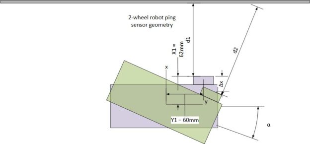
In my last post on this subject, I described some ideas for improving Wall-E2’s wall following performance by compensating for distance-to-wall errors caused by Wall-E2 not being oriented perfectly parallel to the wall. The situation is shown in the diagram below:
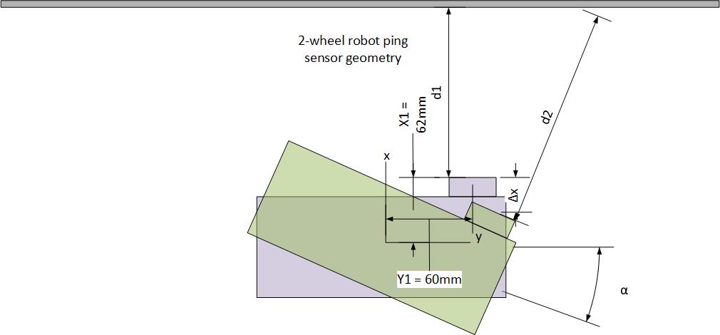
When the robot is parallel to the wall, as shown in light purple, the ping sensor measures distance d1 to the wall. However, when it rotates to make a wall-following adjustment, the ping sensor now measures distance d2, even though the robot’s center of rotation (CR) hasn’t moved at all. If the wall-following algorithm is based strictly on ping distance, the robot tends to wander back and forth, chasing ping measurements that don’t reflect (no pun intended) reality. I need a way of relating the measured distance to the distance from the robot’s CR to the wall, so that wall-following adjustments can be made referenced to the CR, not to the ping sensor position on the robot.
Given the above geometry, an expression can be developed to relate the perpendicular distance d1 and the measured distance d2, as shown below:
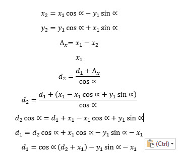
Expression relating perpendicular distance to measured distance for any rotation angle
I set up an experiment where the robot was placed on a platform about 16cm away from an obstacle. I measured the ‘ping’ distance to the obstacle as the robot was manually rotated +/- 20 deg. Then I plotted the data in Excel as shown below:
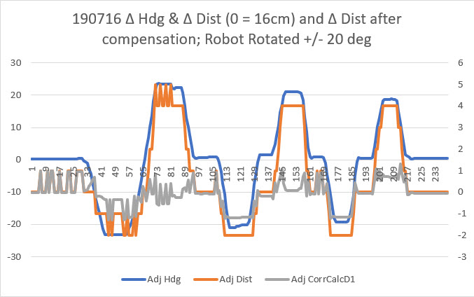
In the above plot, the heading values (blue line) have been normalized to the initial heading and any linear drift removed. After correction, the robot changes heading almost exactly +/- 20 deg. Similarly, the measured distances (orange line) values were normalized to the nominal distance of 16cm. As can be seen, the measured distance varied about +4 to -2 cm, even though the robot center of rotation (CR) remained fixed. Then the distance compensation expression shown above was applied, resulting in the gray line. This shows that the compensation expression is effective in reducing angle-induced distance changes.
Next, I set up a ‘live’ experiment with the 2-motor robot to more closely emulate the normal operating environment. I set up a section of ‘wall’ and had the robot make a single 60 deg turn, starting with the robot angled about 30 deg toward the wall, and ending with the robot angled about 30 deg away from the wall. Distance measurements were taken as rapidly as possible during the turn, but not before or after the turn started.
Here’s a short video of the 2-motor robot approaching a ‘wall’ at an angle of about 30º and making a single turn of about 60º. The entire sequence is about 3 seconds long. The robot runs straight for about 1 sec, then turns for about 1 sec, then goes straight again for about 1 sec.
The measured ‘ping’ distances for the 1-second turn portion of the run is shown in the Excel plot below
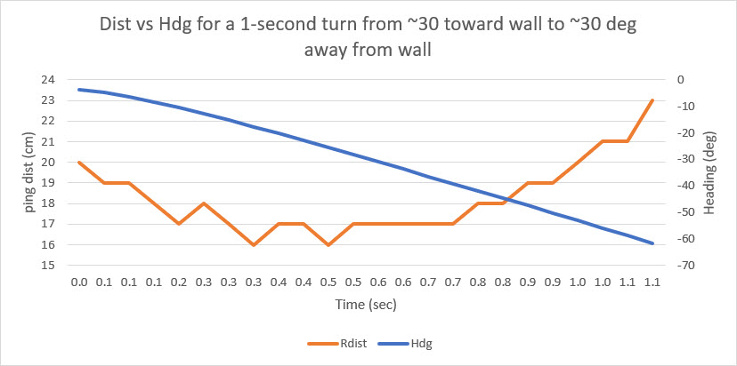
The above plot starts when the robot starts turning at about 1.2 sec into the video (the approach to the wall is not shown). When the turn starts, the measured distance to the wall is about 20 cm. The measured distance decreases rapidly to about 16 cm at about 0.4 sec into the turn (about 1.6 sec into the video), and stays there for about 0.4 sec and then starts climbing rapidly to about 23 cm when the turn finishes. However, the distance from the center of rotation (CR) of the robot to the wall changes hardly at all. The blue painter’s tape in the background of the video has black markings each 5 cm, and it is possible to estimate the distance from the CR to the wall throughout the turn. My estimate is that the robot’s CR starts at about 25 cm, decreases to about 22 cm at the apex of the turn, and then goes back to about 25 cm at the end of the turn. The measured distance decreases 4 cm and then increases 8 cm while the robot’s CR decreases 3 cm and increases 3 – quite a difference, due entirely to the angle change between the robot and the wall during the turn. After normalizing the heading values so that they reflect the angle off parallel and applying the distance compensation expression above, I got the following plot:
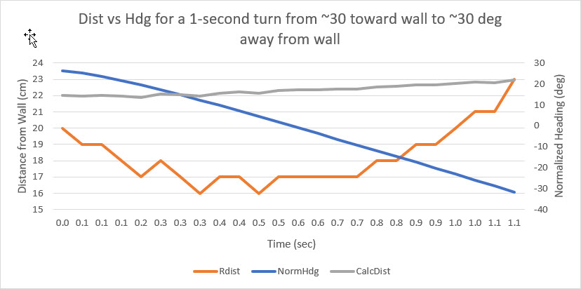
In the above plot, the gray line shows the corrected distance from the robot CR to the wall. As estimated from the video earlier, the CR varies only about 1cm during the turn. This is pretty strong evidence that the proposed distance correction scheme is correct and effective in removing distance measurement errors due to robot heading changes.
With the technique demonstrated above, I am optimistic that I can now not only improve wall tracking, but also can implement wall-following at a specific distance, say 25 cm. The difficulty with trying to displace laterally to acquire and then lock to a specific distance is the large changes in measured difference due to the angle change needed to move toward or away from the wall made it impossible to determine where the robot’s CR actually was relative to the desired offset distance. By (mostly) removing this orientation-induced error term, it should be feasible to determine the actions needed to approach and then track the desired offset distance.
Stay tuned!
Frank
08 February 2020 Update:
As I continued my campaign to integrate heading information into my wall-following robot algorithm, my efforts to compensate ‘ping’ distances for off-parallel robot orientations with respect to the nearest wall kept failing, and I didn’t know why. I had gone through the math several times and was convinced it was valid, and as the plot above showed, it should work.
So, I made another run at it, completely redoing the math from the ground up – and running some more test in my ‘local range’ (aka my office). Still no joy – no matter what I did, the math seemed to be overcompensating, as shown in the plot below:
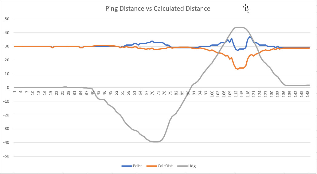
Ping Distance vs Calc Distance for two heading changes
This plot (and others like it) convinced me that I was still missing something fundamental. As I often do, I was thinking about this in bed while drifting off to sleep, and I realized that I might be able to determine the culprit by cheating; I would place the robot at a set distance from the wall, and carefully rotate it manually over a compass rose. At each heading I would manually measure the distance from the ping sensor to the wall, perpendicular to the plane of the sensor (i.e. I would physically measure the distance I would expect the ping sensor to report), and also record the ‘ping’ distance reported by the sensor. With just a few measurements the problem became obvious; the ‘ping’ distance for slant angles to the wall do not even remotely resemble the actual physical distance – it is much less, as shown below.
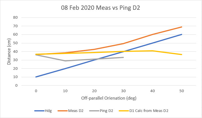
As can be seen , the compensation algorithm actually works quite well, when dealing with the physically measured slant range. However, because the ‘ping’ distance loses accuracy very rapidly off-parallel angles beyond about 20 degrees, the compensation algorithm is ineffective. A classic case of ‘GIGO’.
After performing the above experiment, I was still left with the mystery of why the compensation algorithm appeared to work so well before – WTF? So, I went back and very carefully examined the previous plot and the underlying data, and discovered I’d made another classic experimental error – The ‘Calculated Distance’ data was plotted on the wrong scale. When plotted on the correct scale, the plot changes to the one shown below:
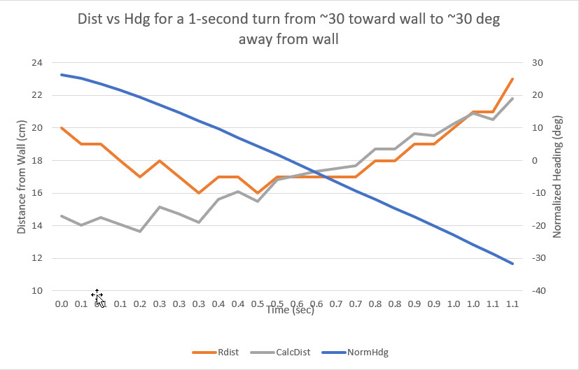
Previous plot with ‘Calc Distance’ plotted on the correct scale
Now it is clear that the calculated compensation using ‘ping’ distances is not at all useful.
So, the bottom line on all of this it that the effort to apply a heading-based ping distance compensation was doomed to failure from the start, because the distance reported by the ping sensor is wildly inaccurate for off-perpendicular geometries. The good news is that now at least I know why the compensation effort was doomed to fail!
In the meantime, I independently developed a technique for determining the heading required for orienting the robot parallel to the wall as the heading associated with the minimum ping distance achieved by swinging the robot back and forth. This technique utilizes the ping sensors in the realm where they are most accurate, and does away entirely with the need for compensation.
Stay tuned!
Frank
