Posted 24 February 2018
I have been working on Wall-E2, my autonomous wall-following robot, for almost three years now, and it seems like I have been struggling with the battery and charger arrangement for that entire time. I started out with 4 AA batteries, but quickly moved on to a pair of Sparkfun 2000mAh ‘flat-pack’ cells with Sparkfun chargers, with a relay to switch the batteries from series (RUN) to parallel (CHG) wiring. This worked, but not very well. The flat-pack batteries weren’t a good match for motor control, and I kept burning up charger modules as well. After struggling with this through several iterations, I finally abandoned it entirely in favor of a 7.4V 20C LiPo RC battery and an external charger. This worked much better, but forced me to manually disconnect the battery from the robot and charge it externally – not at all what I wanted. Later on I made another run at the 2-cell series/parallel switching strategy for charging, this time using Adafruit Powerboost 1000C charge modules, each capable of 1A charge rates. Again this worked (actually quite well), but I recently discovered that it has a fatal flaw – this design imposes significant IR drops on the way from the battery terminals to the motors.
So, I have once again been searching for a solution to the battery/charger problem. While wandering through the Googleverse the other day, I ran across a mention of the 1/2-cell TP5100-based charger module (about 9:50 from start), available for next to nothing on eBay.
Unfortunately, the available technical information on this module is also next to nothing, and what does exist is all in Chinese. Still, this module has the potential for vastly simplifying my charger setup, so I thought it was worth the effort to perform a thorough study.
In a previous post, I described an Arduino controlled charge/discharge test setup for testing operation of my 2-cell parallel/series switched setup, so I decided to modify it for evaluating the TP5100 module, as shown below
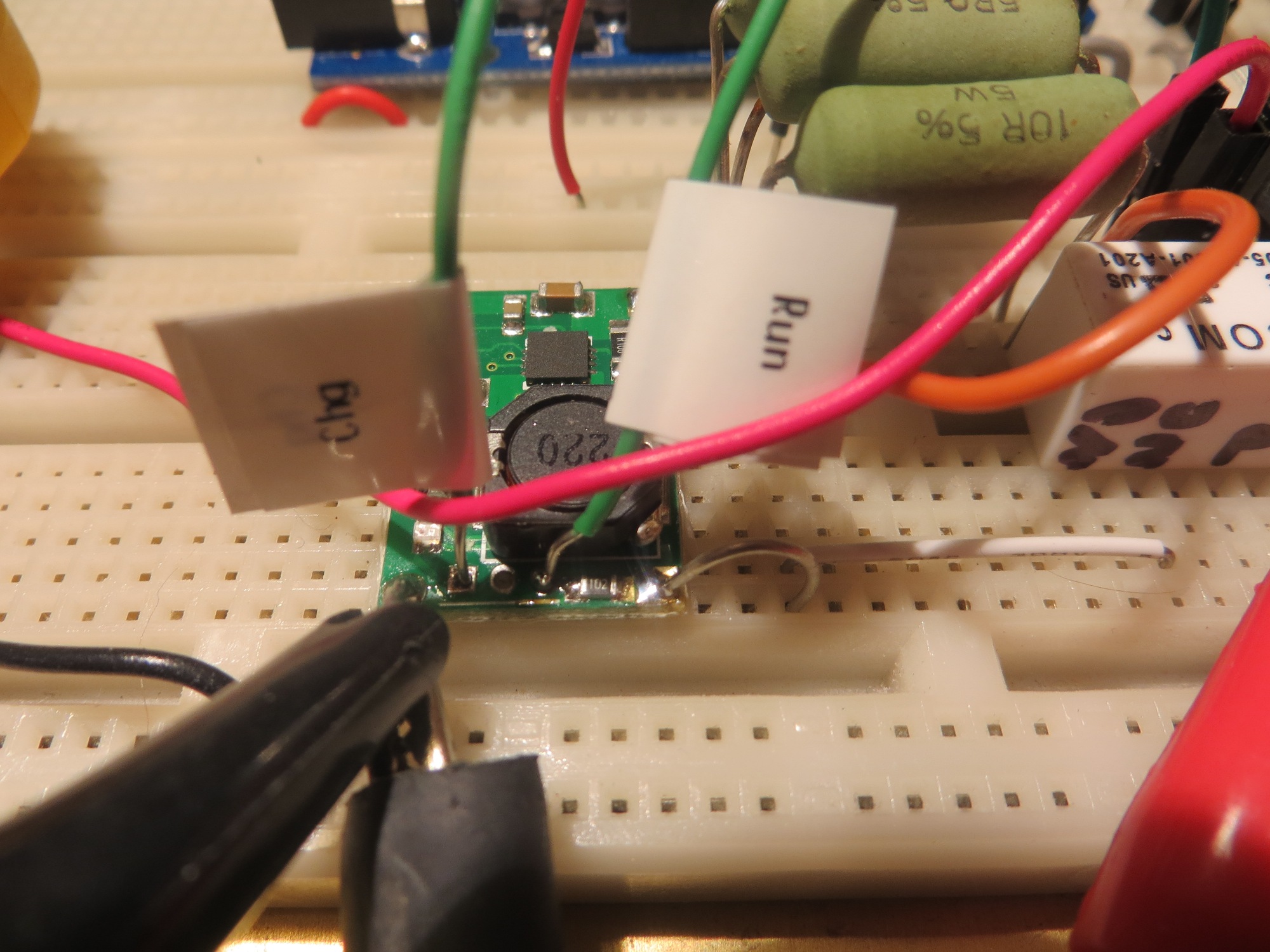
View of TP5100 module showing RUN & CHG indicator connections
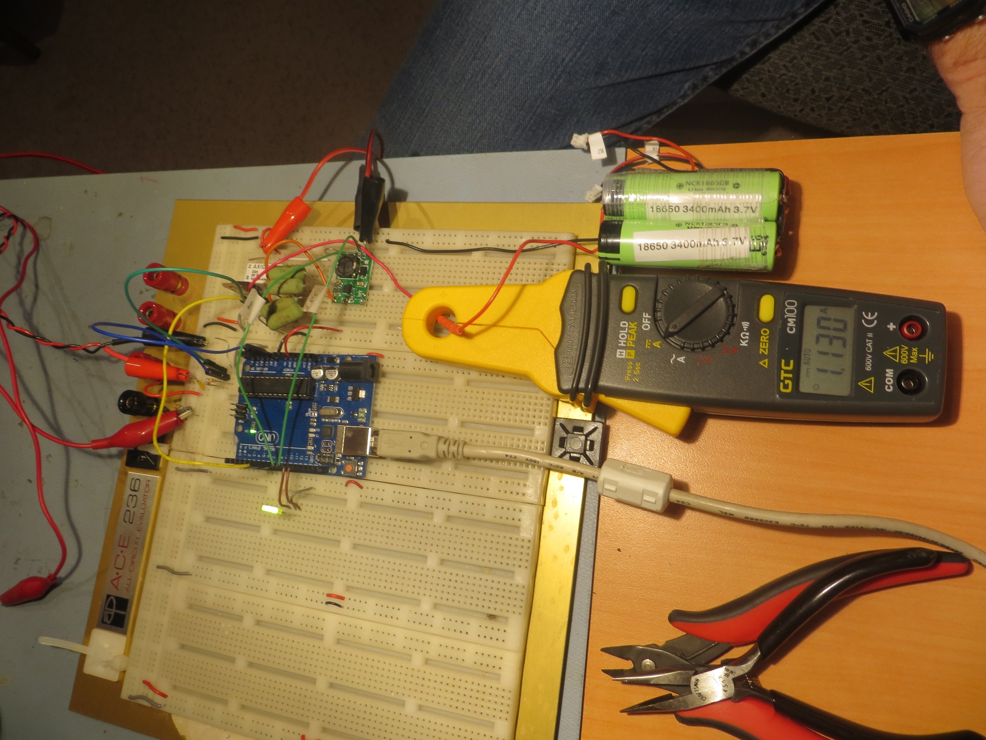
Charger test setup, in discharge mode (note 1.1A discharge current)

Charger test setup, in charge mode (note 1.8A charge current)
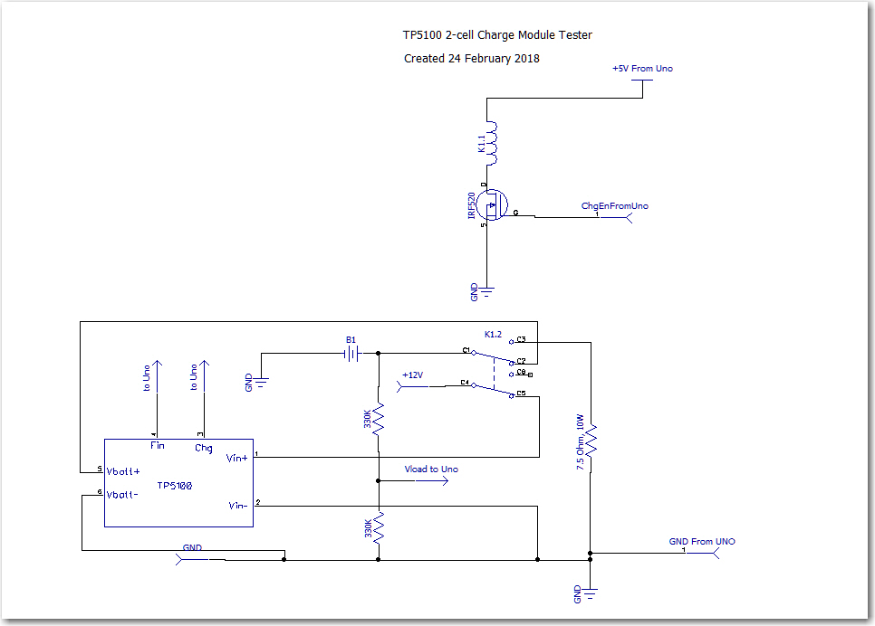
TP5100 Module Test Circuit
Using this setup, I was able to cycle the battery between a 7.5V load and the TP5100 charge module. In order to keep the cycle times down to a dull roar, I set the software to switch to charge when the battery voltage dropped below 7.5V, resulting in the plots shown below.
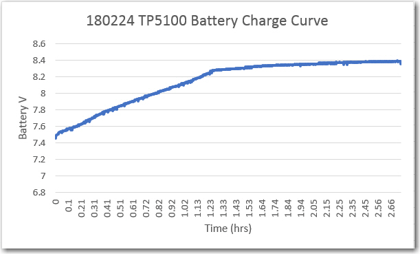
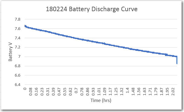
In this case, the discharge current was about 1.1A, and the observed charge current was about 1.8A. The TP5100 modules seems to work as advertised – with a 12V 5A power supply and a partially charged battery, it successfully charged my 2-cell LiPo pack terminated the charge at about 8.4V (I’m not sure if it is terminating based on current or voltage).
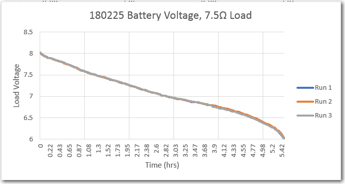
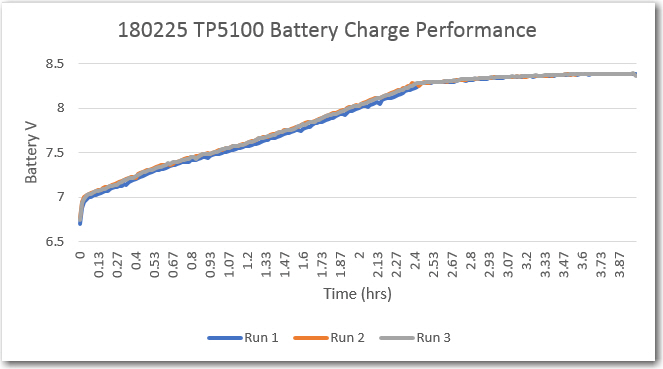
Over the next couple of days, I performed three complete charge/discharge cycles using this same setup. Discharge was terminated at 6V, and charge was terminated when the TP5100 ‘complete’ output changed from open-circuit to active-low. As can be seen in these charts, performance was very consistent – almost 6 hours run time into a 7.5V load, and about 4 hours for a complete recharge.
So here’s what I know now about the TP5100 module
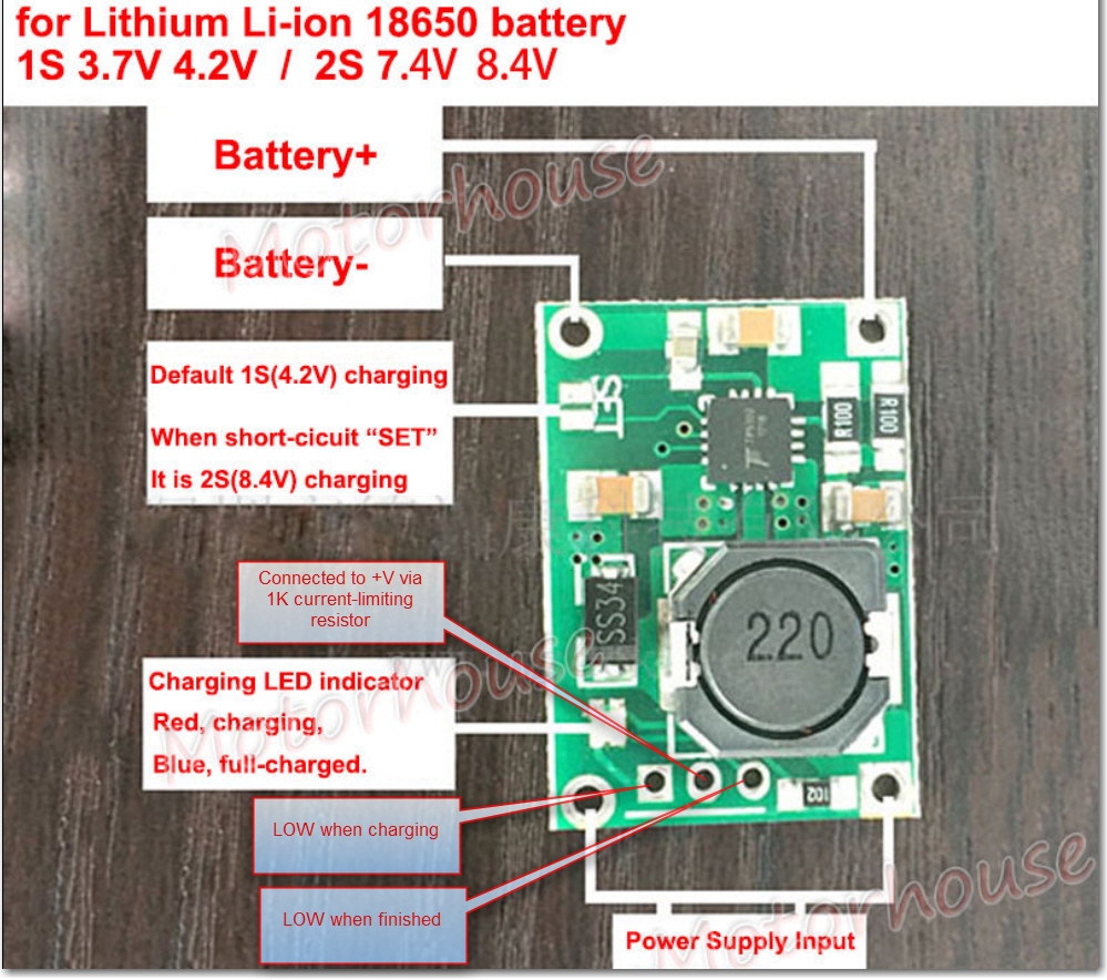
- When the ‘1-cell/2-cell’ jumper selector is shorted to select 2-cell, the output voltage stabilized at 8.4 with a 10-15V DC input (I used a 12V 5A supply for the tests). Below about 10V, the output voltage falls below 8.4V
- with a partially charged battery stack, output current was about 1.8A at the start, tapering to below 200mA at termination
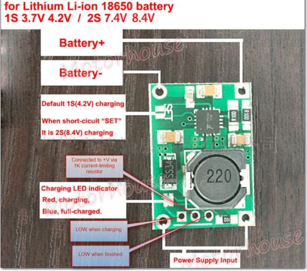
- There is an onboard Red/Blue LED and solder holes for an external bi-color LED. The onboard LED states are:
- RED = Charging
- Blue = Finished
- Both the onboard and external LED connections are tied to +V via the same 1K current limiting resistor. This resistor is routed to the center hole of the 3-hole external LED breakout. The rightmost hole is tied to an open-collector gate that goes LOW upon charge termination, and the leftmost hole is tied to an open-collector gate that goes LOW upon charge initiation. In my testing circuit above, these lines are labelled ‘Fin’ and ‘Chg’ respectively and were routed to digital inputs with 20K pullups on the Arduino UNO.
- This is NOT a balance charger – so there may be differences in cell voltages over time. If this is a potential issue, then separate cell protection modules like these should be installed.
Here’s an annotated photo showing the pertinent features:
So, it looks like this TP5100 module will work fine for my 2-cell LiPo application, with the addition of an external 2-cell protection module like the one noted above. Not only will this solve my original IR drop problem, but it is much smaller and simpler too, as shown in the following size comparison shot. Oh well, at least I had a lot of fun building up and testing the original charger module ;-).
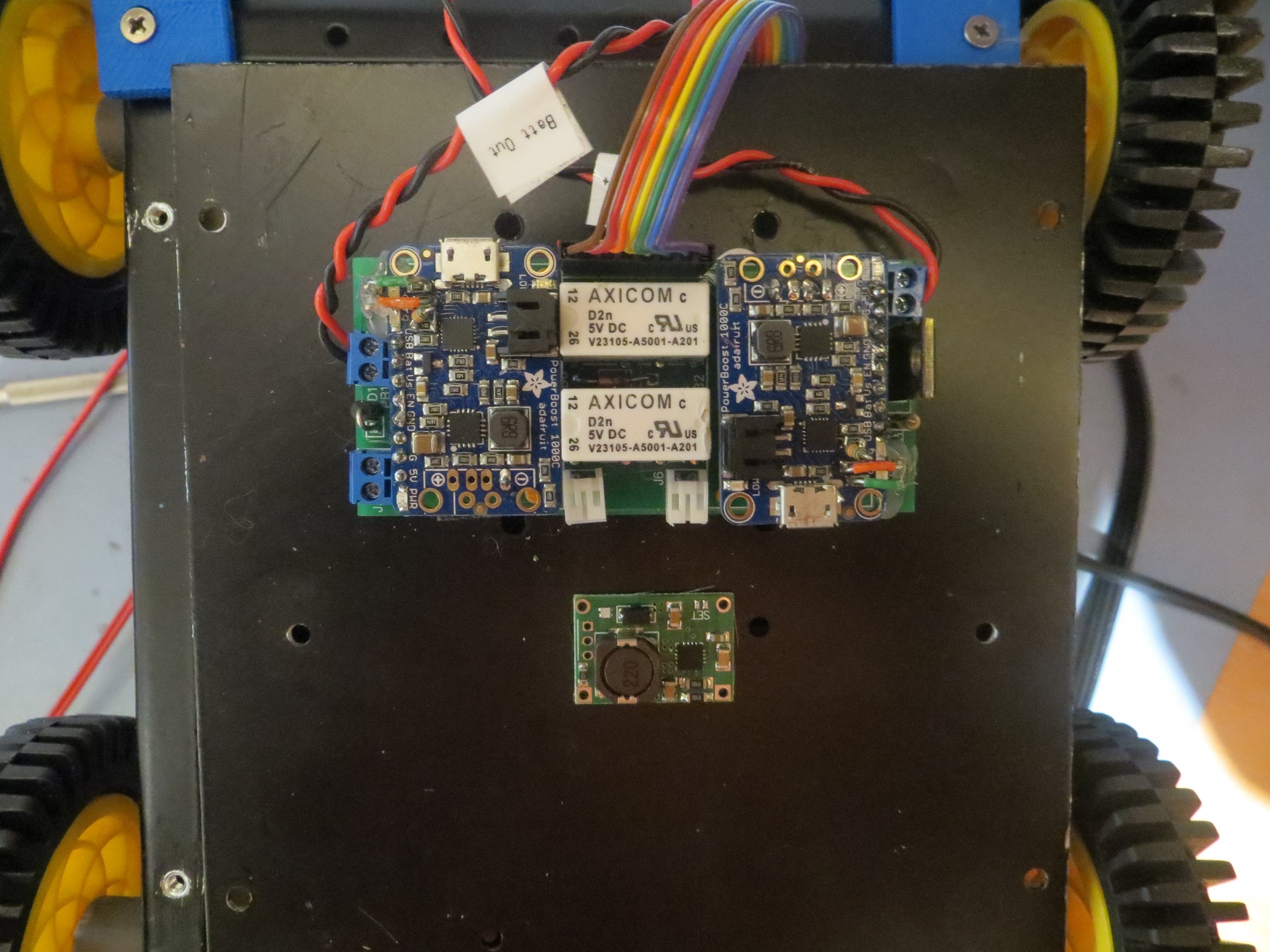
charger module and TP5100 size comparison
Stay tuned!
Frank
Pingback: New TP5100-based Battery Pack for Wall-E2 - Paynter's Palace
Could you by chance tell me what the value of the ceramic caps are on the tp5100? trying to create an all in one PCB
Sorry, they aren’t marked at all. If that is critical, I recommend you buy a couple of TP5100 modules and measure them yourself – they are dirt cheap!
Frank
Nice test, thank you for sharing it.
You wrote “I’m not sure if it is terminating based on current or voltage”
It terminates on the current. In the second stage you should see a constant voltage charging, and it is terminated by the current dropping below the threshold value. In your diagram the voltage appears not to be constant. Actually it is constant on the BAT terminal of the TP5100, however due to the resistance of wiring and relay contacts it is still increasing on the terminal of the battery.
I purchased 12 pieces of this circuit, out of them 6 failed immediately after switching on 12 V input. In 4 circuits the TP5100 burned (a hole and even sparks out of them appeared). 2 others did not burn, but directly output the input voltage.
The rest of them work fine.
Thanks for the input, but I had no trouble with either of the units I got. Both worked fine, once I figured out how to enable the 2-cell configuration
Unfortunately in China there are many illegal copies, sometimes even the original manufacturer has problems to tell if it was their make. In the last years I had similar experience with two integrated circuits, one of them was a 3.3V supply which failed over 6 V input, while specification was 12V. It turned out that I purchased a fake product…
I purchased 5 of TP5100 from Aliexpress. Two of them burnt out immediately, the third charged but burnt out when connecting another DC supply. Learning (as for now):
1 – NEVER connect the input to pulsed DC (rectified AC). These modules seemingly accept only flat DC voltage.
2 – Perhaps it can help to add a series resistor (1-2 Ohms) and a larger capacitor to the input. Probably this does not help for rectified AC as that would require extremely large capacitor. (several thousand uF )
Now I have still two of them, I can try.
The first one I bought worked fine from 9V, after I used 12V it too burnt out and applied 12V directly to the output. I bought another which has been fine. I also bought a TP5100 chip to replace the one on the faulty module, though I haven’t actually done this yet.
Dunno, guys. It worked at the first power on. I bought 3 pcs from Ebay diler (https://www.ebay.com/itm/292606804895), all working. I liked this charger better than TP4056, because heats up a bit lower (TP4056 requires little heatsink). 2-cell scenario went very good, charging stops at 8.4V level. I used generic QuickCharge USB smartphone charger and a trigger (https://www.ebay.com/itm/322461068691) to get 12V supply. The only drawback of TP5100 can be lack of balance function, and cell protection MOSFETs, but these are available too at Ebay/Aliexpress/etc. I charge SONY SRS-XB20/30/40 batteries, they are protected. Thanks for reading)
Pingback: Divergence Meter Battery Mod - nixies.us
Hi, I purchased 10 of them trough Banggood and already six of the TP5100 failed miserably. (With all of them the TP5100 IC failed)
The problem seems to be with some sub standard components and I studied the circuit and the badly translated document so I redid the document as well as I could.
The main problem seems to be with the Schottky, the SS34’s reverse leakage current maybe just to high for the IC.
Im ordering MBRS540T3G (RS-Components number 688-0512) with an reverse leakage of 300uA as a replacement for the six that survived. Im also going to replace the remaining 10uF caps for just in case and also the 100nF cap. I’m going to use a low ESR 10uF cap from TDK with a 10% tolerance (RS-Components number 903-9170). All the components footprint is the same as the current. I’m also thinking about replacing the two 100 mili ohm resistor with a 1% tolerance 50 milli ohm 1W resistor (RS-Components number 126-0398) that is specifically for current sense purposes just to be on the safe side (The items takes way to long to reach me to risk the remaining four and with sensitive devices like the LiPo batteries high risk)
I have improved the translated document on the TP5100 and made some notes in PDF format If you are interested.
Hope this help
Now I have 11 working modules. Out of them 3 leaks about 6-8mA from the battery when power supply is not connected… I learned, that some Chinese IC manufacturers also sell the parts which are out of specs. Probably this is the case here.
@Eugene Lindemann: Thank you for the input on SS34 problem, which is very likely the cause of failures in my experience.