Monthly Archives: January 2018

Printing an ABS Shaft Adaptor for 80mm Wheel

Posted 25 January 2018

Over the last few days I have been struggling with a project to 3D print a small adaptor to allow me to mount some 80mm wheels I bought some time ago to my Wall-E2 autonomous wall-following 4-wheel drive robot.

The original robot came with 56mm wheels and this gave Wall-E2 very little ground clearance.   I found some 80mm wheels that I thought would do the trick nicely, but when I tried them, it quickly became apparent that the shaft receptacle on the wheel was significantly larger than the motor shaft, leading to a very bad wobble and catastrophic wheel departures – oops!
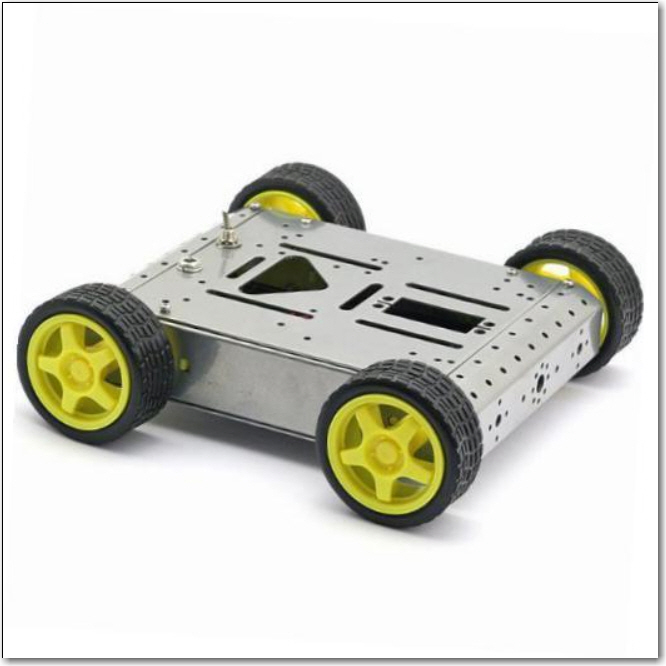
Lightweight 4WD Drive Aluminum Mobile Dolly Car Robot Platform for Arduino
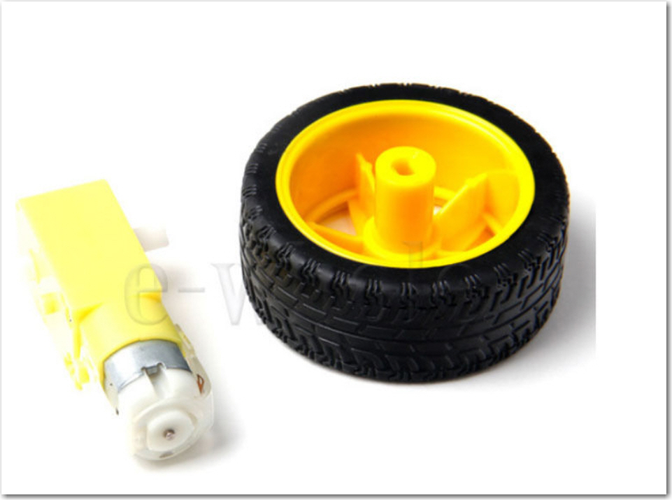
 

original 56mm wheel and companion motor
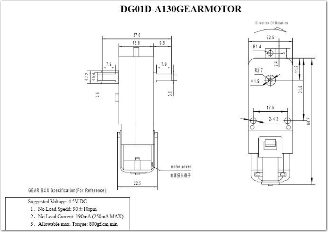
Ebay ‘Arduino Robot’ motor dimensions
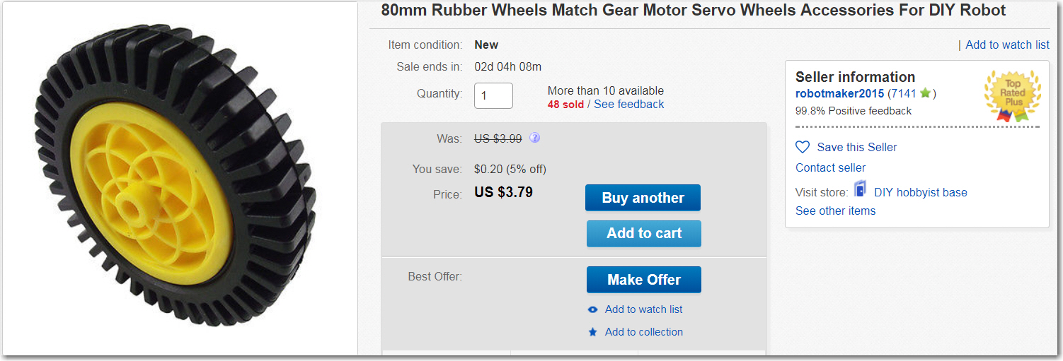
80mm wheel

After some troubleshooting, I discovered that the new 80mm wheels have a shaft receptacle that measures 5.9mm long and 3.6mm wide, while the motor shafts are 5.4mm long and 3.5mm wide.   The width is OK, but the longer length is causing the problem.

After thinking (and cursing) a bit, I decided to try printing an adaptor.   The larger diameter wheels are also considerably thinner (20mm or so vs 30mm), so there should be room for an adaptor part, as shown below
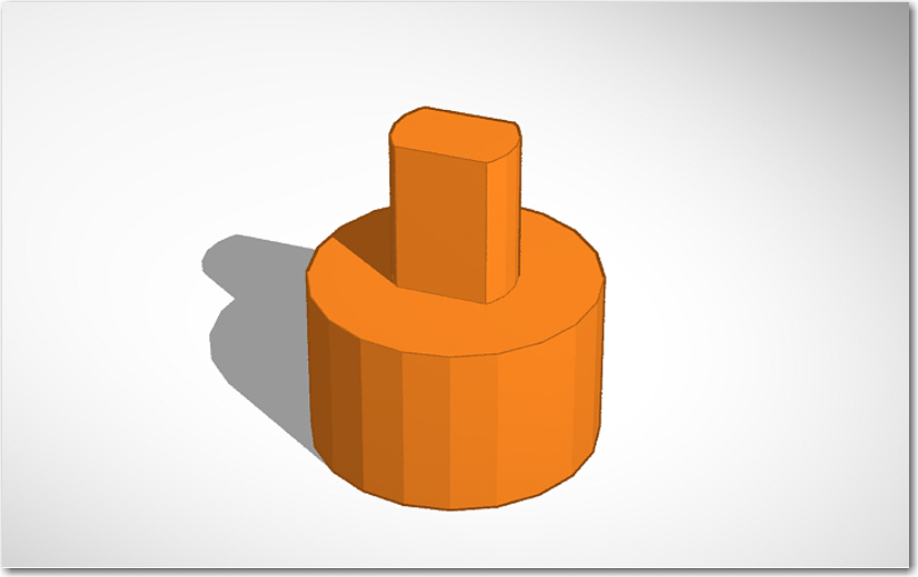
shaft adaptor for 80mm wheel

And threw it on my PowerSpec 3D PRO (Flashforge Creator Pro knockoff).   After just a little fiddling, I got some nice parts, and thought I was done.   A couple of days later, I noticed one of the parts was just a little loose on its shaft, so I said to myself – “I’ll just print off another one”.   Unfortunately, what came off the printer was really ugly, and completely unusable, even though that same printer had produced nice parts just a few days ago – WTF!?   Clearly I had forgotten what magic I had wrought the first time, so now I had to go back and recreate it – bummer.   As part of my penance for this crime, I am writing this post so the next time I want to do this, I’ll have the print settings recorded.

Print Settings for ABS

The significant factors in how to get good prints with ABS on this printer appear to be

  • Print speed
  • Extrusion factor

The first thing I did was slow the print speed down, but this had only a minor effect on print quality.   Going slower helped, but even very slow speeds (like 10mm/sec) didn’t result in clean edges on the male part of the adapter. However, the female portion was very clean, which left me a bit puzzled – why one part but not the other?   I finally realized that the difference was that the female piece was perfect because the hole perimeter was the first thing laid down at each slice, then the outside perimeter, and finally the fill material was added last.   This meant that the hole perimeter had a chance to cool and solidify before the fill material impinged on its outer surface, and this meant that the perimeter stayed in the same shape as originally laid down.   When printing the male part, however, the outer perimeter was laid down first, and then the fill material was immediately added, before the outer perimeter had a chance to cool and solidify, even at the slower speeds.   The material making up the fill was pushing the outer perimeter out of shape.

This led me to focus on the extrusion factor.   Reducing the extrusion factor from 1.00 to 0.95 had a significant positive impact on the print quality of the male portion of the adaptor.   Reducing it again to 0.90 resulted in an even better print, as did a further reduction to 0.85.   However, at the 0.85 value, I started to see some degradation in the quality of the female portion, so I backed off to 0.90 as the final value.   The following image shows the last seven prints.   All were printed at either 20mm/sec or 10mm/sec, and the last three on the right were printed with 10mm/sec and extrusion factors of 0.95, 0.90, and 0.85 respectively.
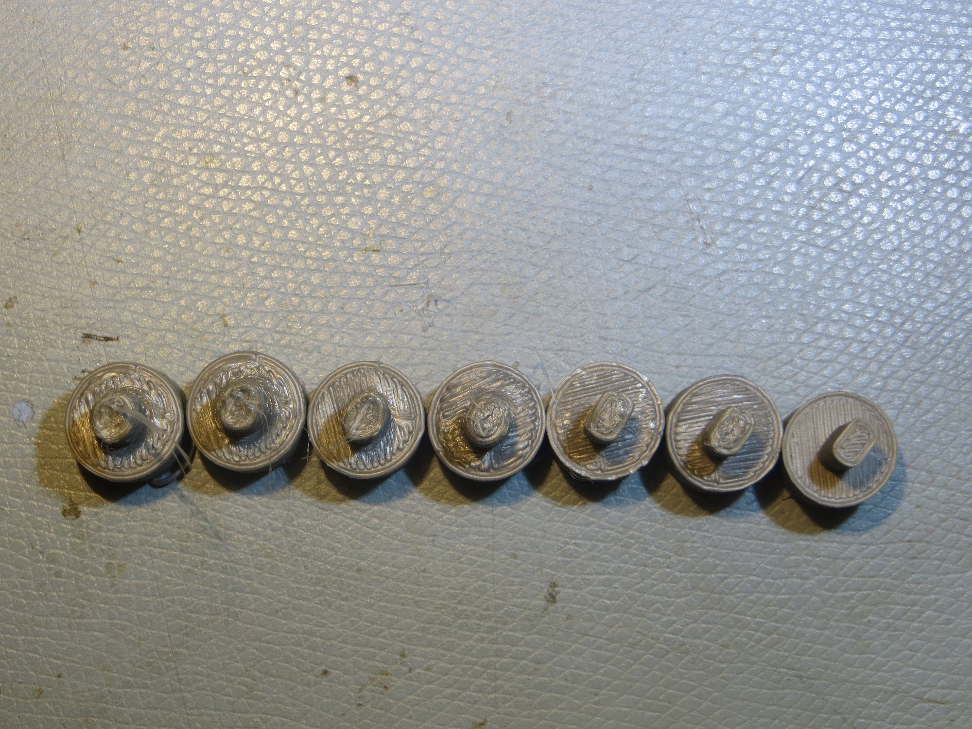
The last seven prints. the last three on the right were printed at 10mm/sec and with extrusion factors of 0.95, 0.90, and 0.85 respectively
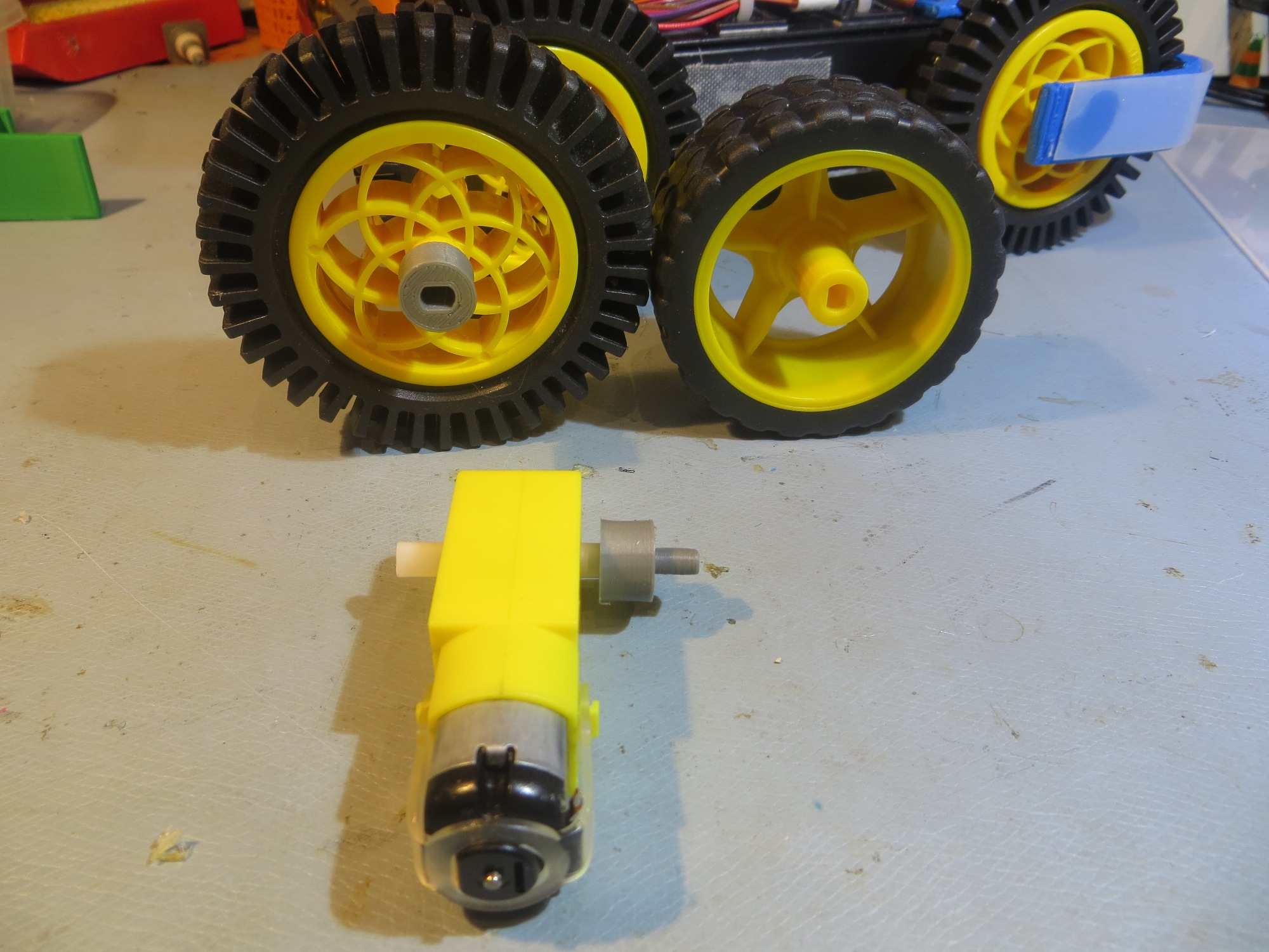
Original and new wheels, with completed adaptor shown

Bottom Line (PowerSpec 3D Pro, Simplify3D):

  • Material: Gray ABS
  • Extruder temp: 230 (not critical 220-240 should be OK)
  • Bed temp: 110 (not critical, 100 should do too)
  • Speed: 20 or 10mm/sec (maybe faster would be OK, but not much)
  • Extrusion factor: 0.95 or 0.90


A New Chassis For Wall-E2, Part III

Posted 13 January 2018

Back in November of last year I started moving Wall-E2 to his new home in a larger chassis, and subsequently I was able to integrate the new-improved charging system in to this new chassis.

So, today I started some field testing, and discovered a major problem – the motors that came with the new chassis don’t have sufficient torque to handle the operating environment – they stall out much too quickly when encountering any movement issues at all.   This wasn’t a problem for the previous incarnation of Wall-E2, so clearly the motors that came with the new chassis have different speed/torque specs than before.   And, of course, the old motors won’t fit into the new chassis (actually, they do fit, but not with the new battery pack).    What a bummer!

So, I started researching dc motors to determine if I could find motors with the speed/torque specs of the old chassis, but with the physical specs of the motors that came with the new one.

Motors in previous ‘Pirate’ chassis:

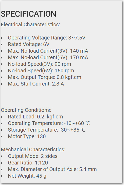
The specs for the motors that came with the DF Robots ‘Pirate’ chassis are shown below:

Specifications for the motors using in the ‘Pirate’ robot chassis from DFRobots

With a gear ratio of 160, the motors should produce about 160 RPM at At Wall-E2’s normal operating range of 6-7.5V, and can produce a maximum torque of 0.8 kgf-cm (kilogram force – cm).

Motors in new chassis:

A DRIVE MOTOR GEARBOX REDUCTION RATIO: 1:48
DRIVE MOTOR NO-LOAD SPEED: 220RPM

I couldn’t find the max torque specification, but assuming it’s the same basic motor body, the much lower gear ratio should result in the observed higher no-load speed and lower torque.

So, I’m fairly confident that I now know  why the motors in the new chassis aren’t performing as well as the old ones – a much lower gear ratio.   Now all I need to do is find another motor source with the same form factor as the new ones, but with a gear ratio more like the ones from the older chassis:

Pololu:

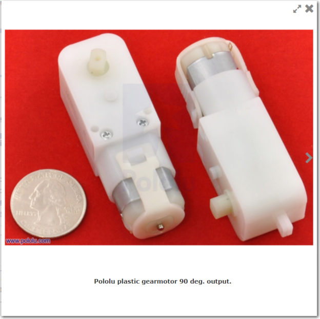
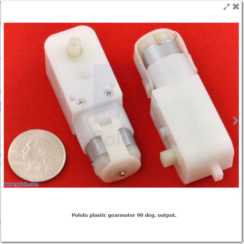
I found a 120:1 gear ratio right-angle motor at Pololu

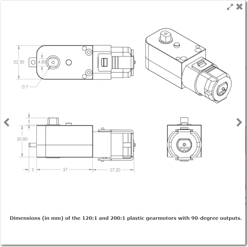
Pololu 120:1 right-angle motor dimensions

Pololu 120:1 right-angle motor

These motors have almost the same exact dimensions as the ones in the new chassis,  but they have a shorter (5 vs 9mm) and larger diameter shaft (7 vs 5mm).   These are not insurmountable difficulties, but surely I can find a better fit.

Ebay:

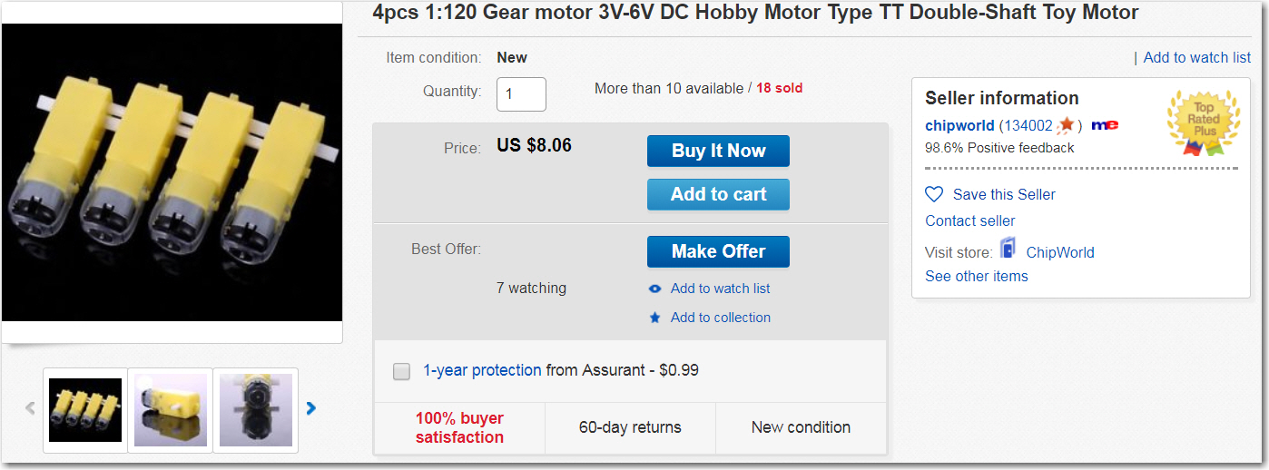
So, eventually I ended up back on eBay, the same place where I got the new chassis.   But, this time I was a little more informed about what gear ratio I wanted, and so was able to reasonably quickly locate a set of 4 motors (without wheels – I have too many already!), as shown below

4ea 1:120 right-angle shaft motors with 5mm shaft diameter

So, now all I have to do is wait 2-3 weeks for them to arrive, and I should be back in the low(er)-speed, high(er)-torque business!

Stay tuned!

Frank


Wall-E2 battery charger module integration

Posted 01 January 2018

What a way to start off the new year!   The battery charger module for my autonomous wall-following robot Wall-E2 has been completed and tested, and now has been integrated into the robot – yay!!

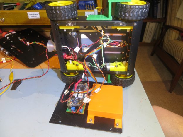
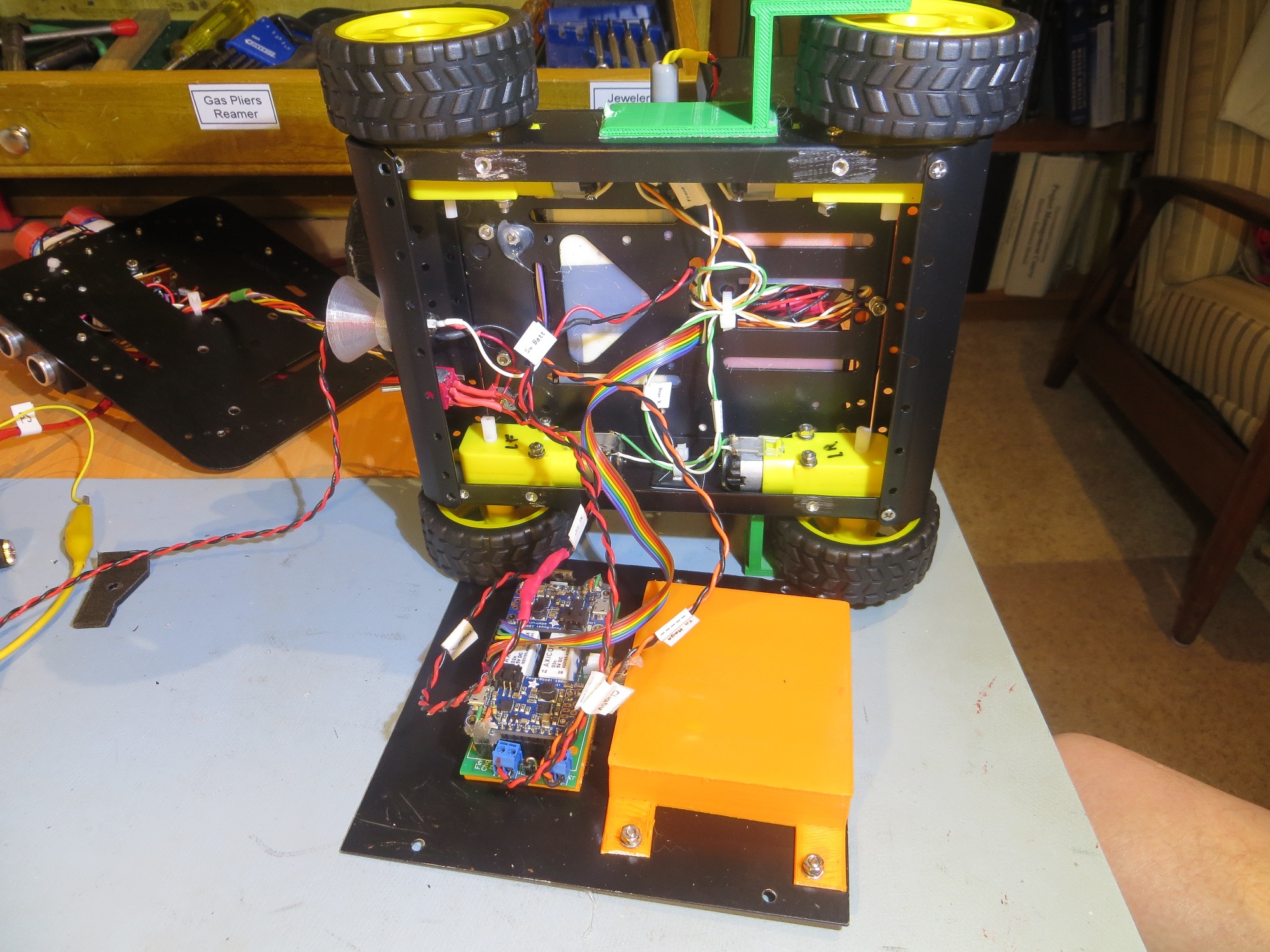
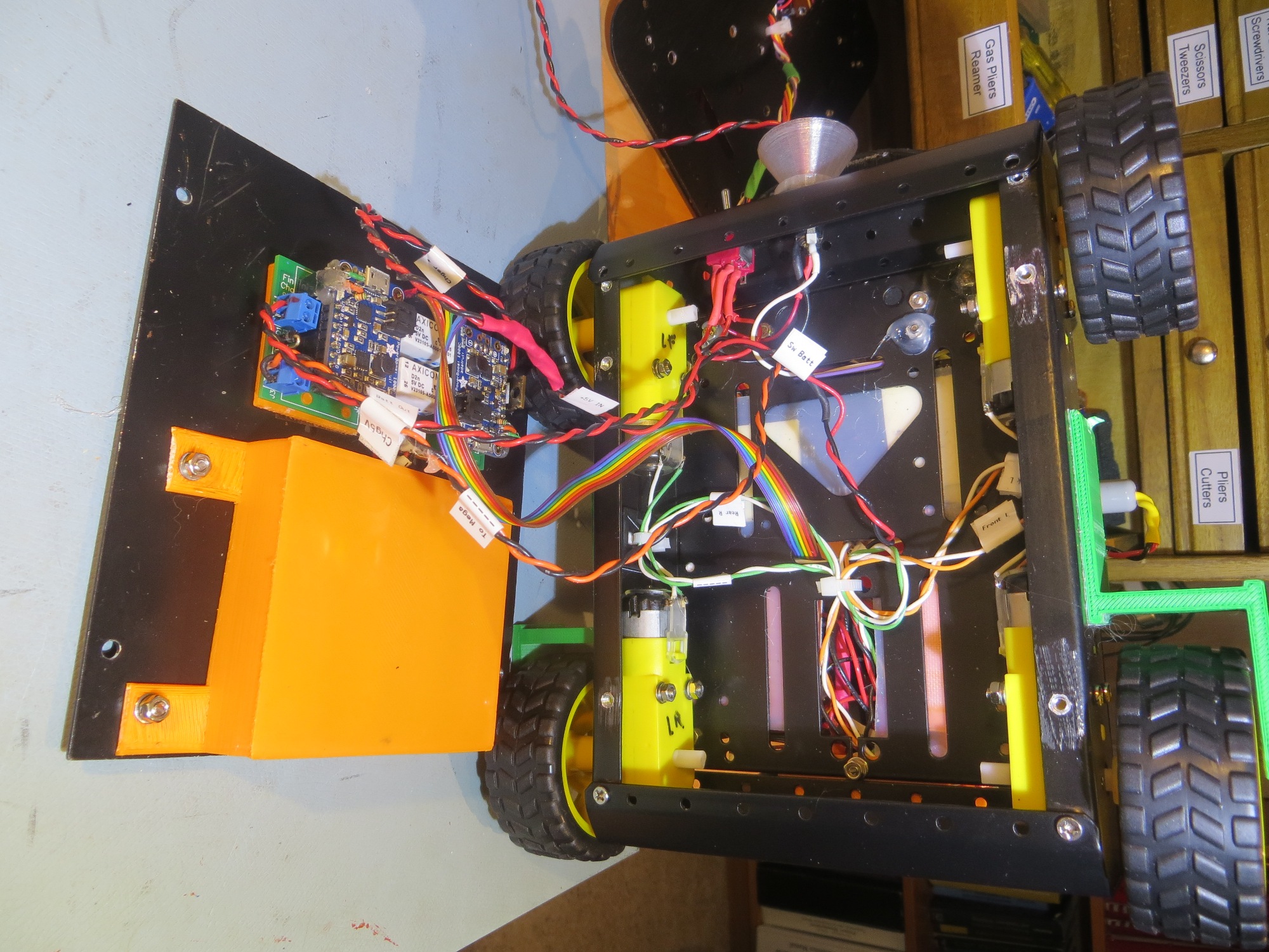
If you have been following this saga, you will recall that I started working on an internal charging module for Wall-E2 well over a year ago, back in November 2016 with this post.   Since then I have gone through several iterations, revisions, and mis-steps (including a semi mind-boggling deep-dive into the details of the Adafruit PowerBoost 1000C specifications in this post).   Last month I finally got a complete system (two PowerBoost 1000C’s integrated onto a single PCB with appropriate control and battery switching circuitry) working, and was able to run extensive charge/discharge cycle testing using a simple test circuit and an Arduino Uno to run it. So, now all I had to do was stuff the whole thing back into the robot.   This task was made possible by my earlier decision to upgrade Wall-E2’s ride to a slightly larger chassis, so instead of trying to cram 2Kg of battery/charger into a 1Kg space, I now had the pleasure of fitting 2Kg into a 3Kg space – nice!    Here are some photos of the integration process.

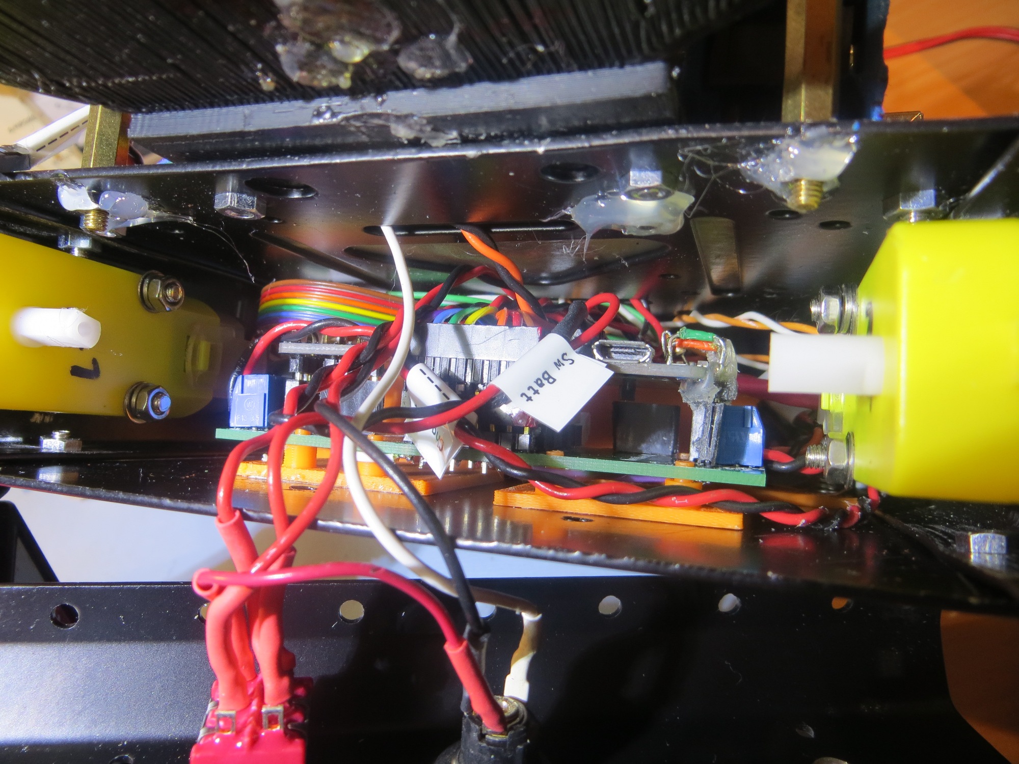
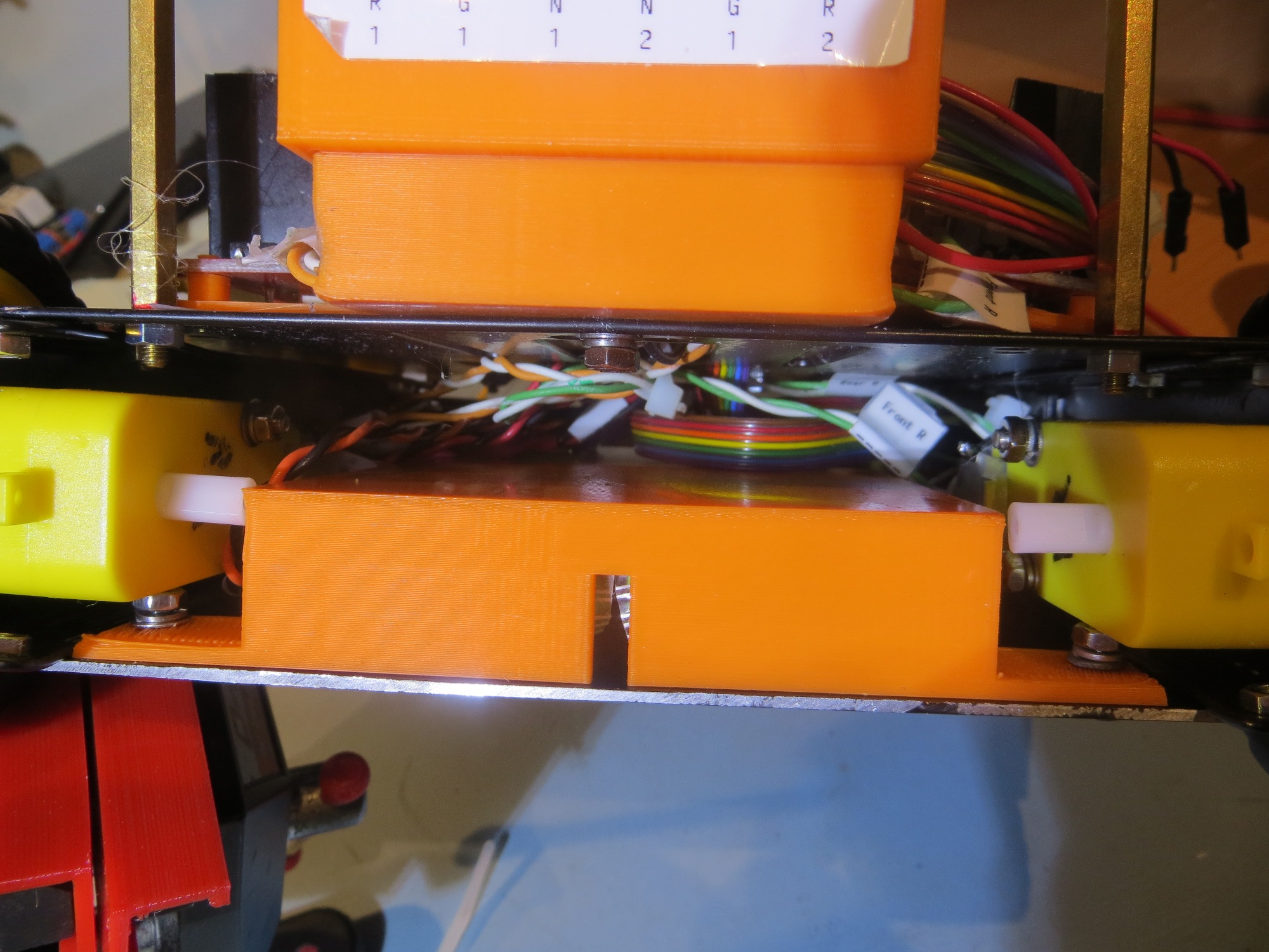
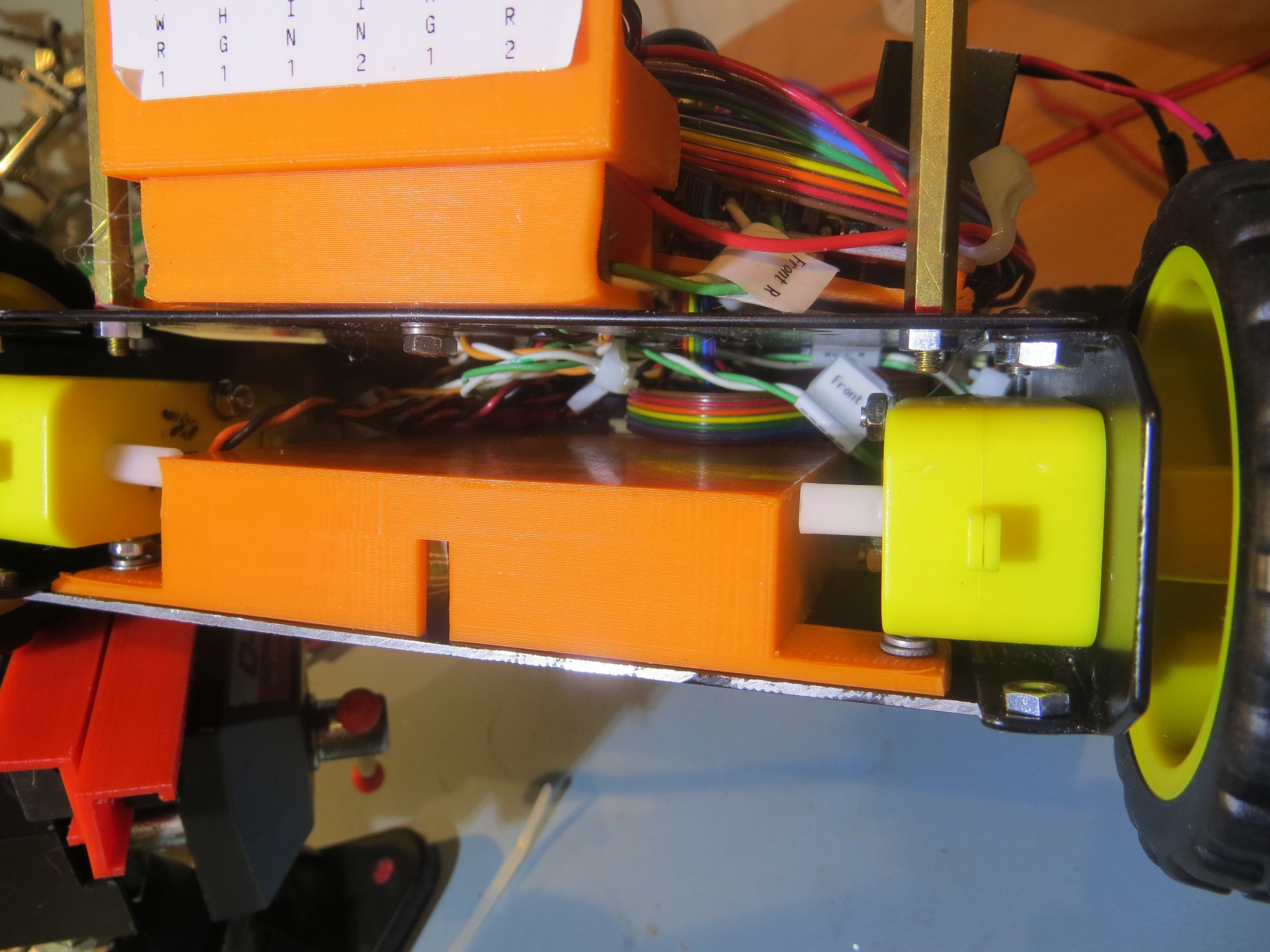
Battery module shown in the ‘maintenance’ configuration.

Another shot of Battery module in the ‘maintenance’ configuration.

Front cover removed to show how the battery module fits into the robot. Note there is plenty of room for cable runs

Front cover removed to show how the battery module fits into the robot. Note there is plenty of room for cable runs

Rear cover removed to show how the battery module fits into the robot. Note there is plenty of room for cable runs

Rear cover removed to show how the battery module fits into the robot. Note there is plenty of room for cable runs

Now that the battery/charger module has been integrated into the robot chassis, I will have to make some minor changes to the robot operating system to accommodate changes I have made along the way, but these should be easy and straightforward.   Then, it will be back to field testing, I hope.

Stay tuned!

Frank