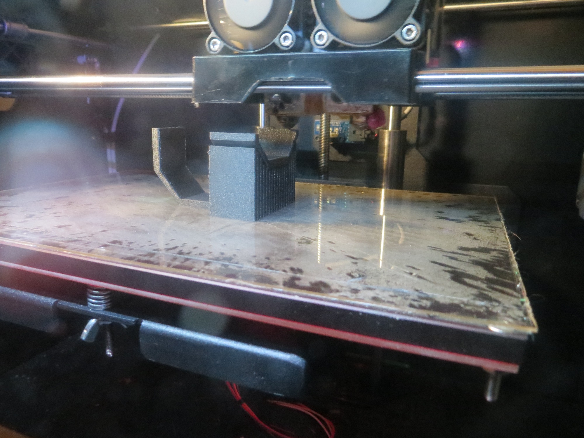
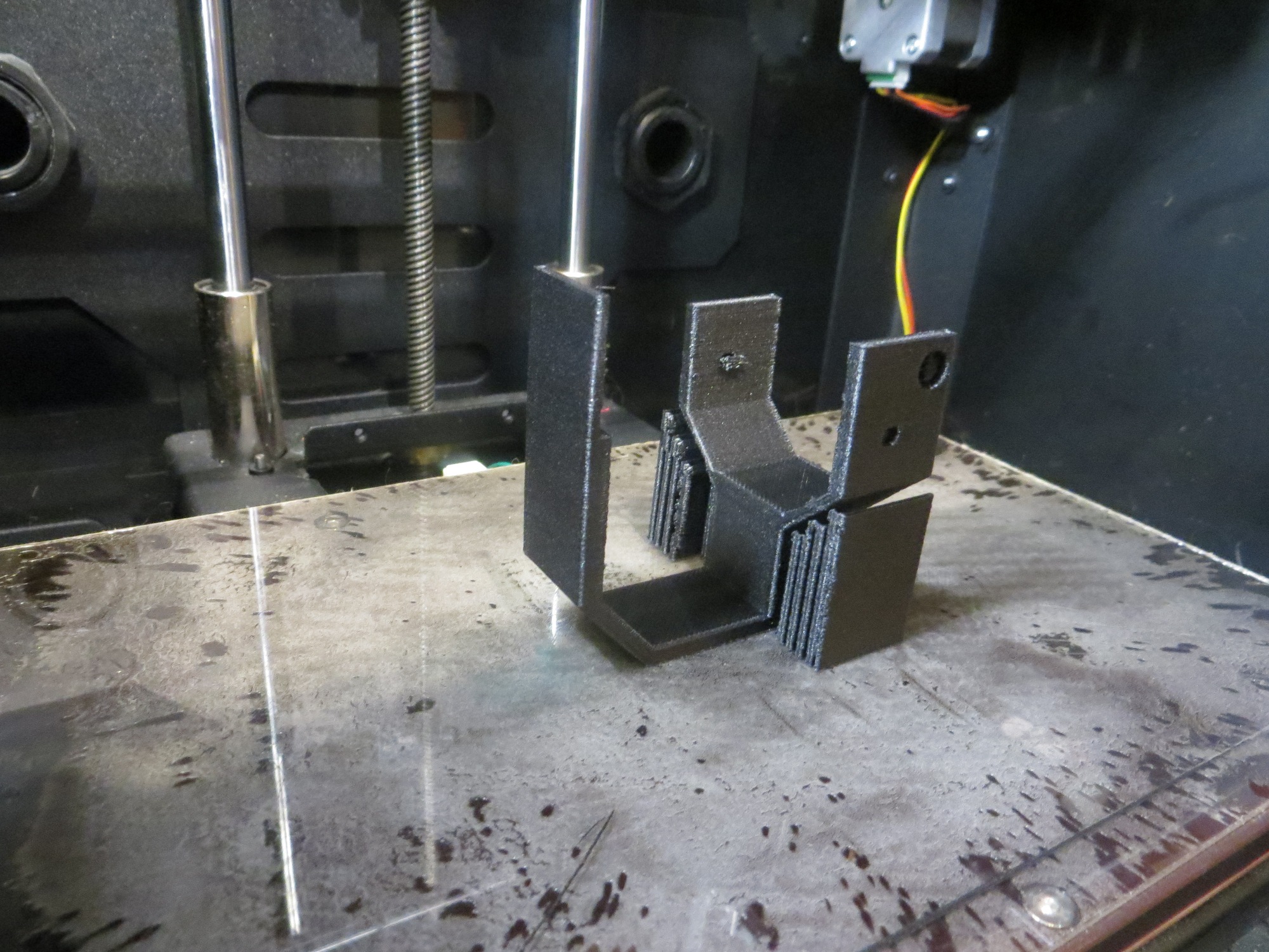
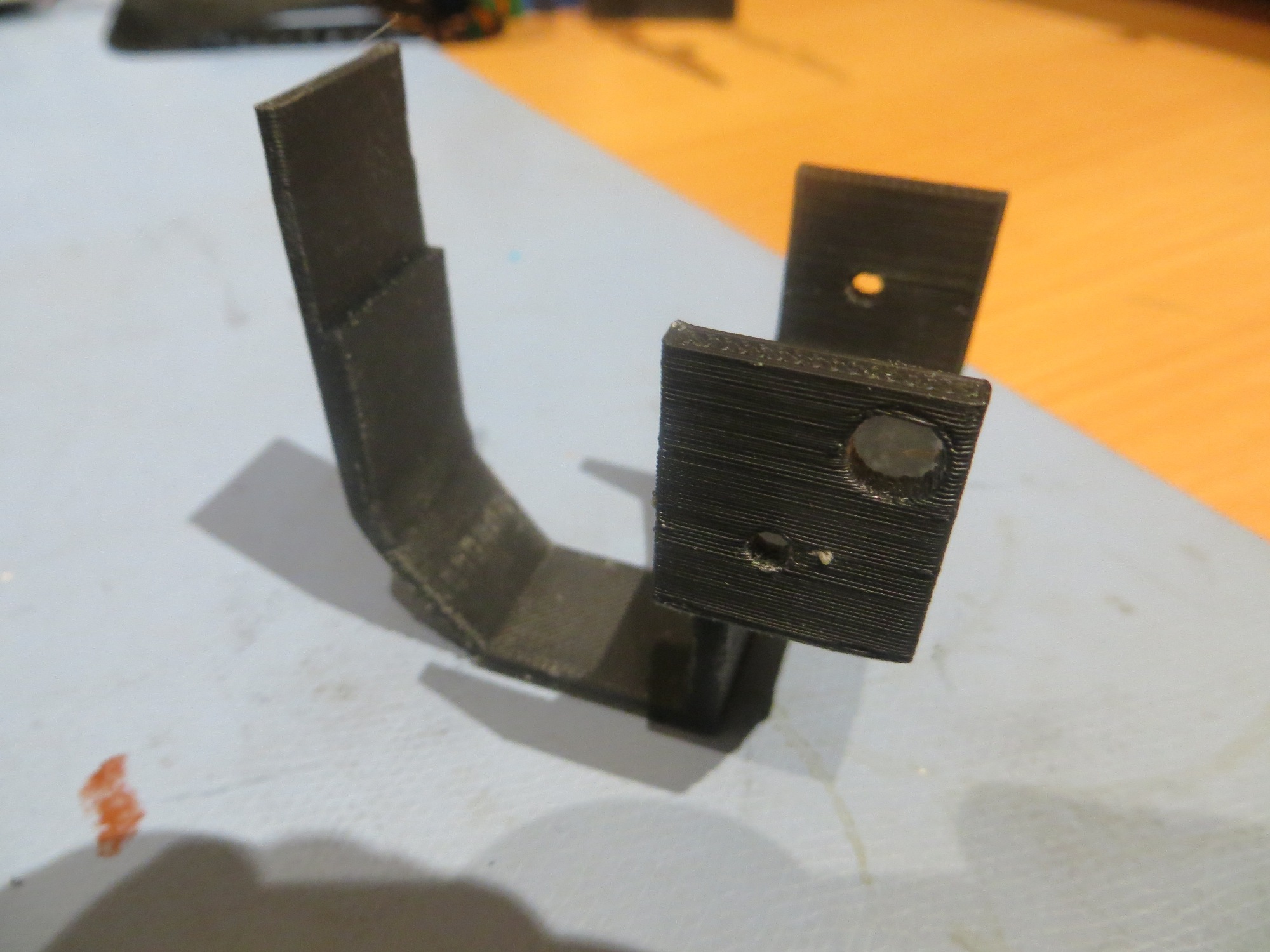
Yearly Archives: 2017

Charging Station System Integration. Part IV

Posted xx  April 2017

While doing the hallway testing that led to the  discovery of the overhead IR ‘noise’ problem and the design of a ‘sunshade’ to suppress that noise and implementation of the flashlight reflector idea for the IR LED, I discovered several other problems with the operating system, as follows:

  1. Once the software detects an IR signal, it switches in to IR homing mode, but the only way back out again is to either execute the avoidance routine if it isn’t in need of a charge, or by connecting to the charger and then disconnecting once the battery is fully charged.  There’s no provision for error cases, like getting stuck on on of the lead-in rails.
  2. The charging station disconnect maneuver needs work – it doesn’t back far enough away, and doesn’t turn far enough to actually get away from the charging station.
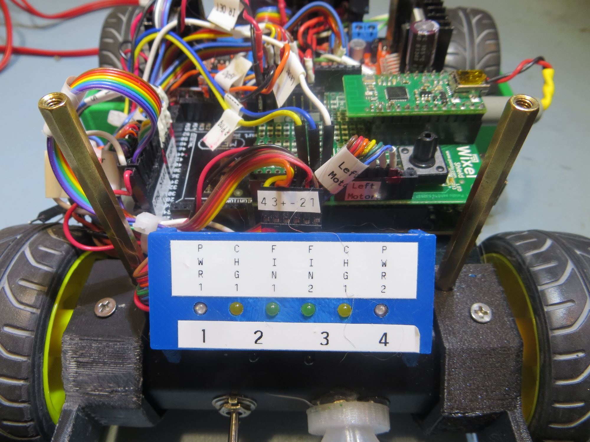
  3. The routine that monitors the charging state needs work. On several occasions it detected ‘end of charge’ when one of the chargers momentarily switched  from ‘charging’ to the ‘finished’ state and back to ‘charging’.  The software should not declare ‘end of charge’ until both chargers’ status is ‘finished’, and the software should employ  integration  to handle momentary state changes.

Item 1 – Exit provisions for IR homing code

This item actually turned into a full-blown rewrite of Wall-E2’s operating system software structure.  As I looked at the code to determine the best way to implement the required error case detection/responses, it became apparent that the problem was ‘baked-in’ to the software system design, and would have to be addressed at that level.  So, I went ‘back to the drawing board’ (in this case to Microsoft Visio) and reworked the system design to allow Wall-E2 to detect and respond appropriately to error conditions in any mode, not just the normal wall-following one.  The revised structure charts are shown in the following PDF document:

Loader Loading...
EAD Logo Taking too long?

Reload Reload document
| Open Open in new tab

Download

In the revised structure, the system always returns to the ‘Determine Op Mode’ block after each pass through the system, without getting stuck anywhere.  This means that the ‘GetOpMode()’ routine has the opportunity on each pass through loop() to detect error situations (like the ‘stuck’ condition) and respond by switching to the appropriate branch of the structure tree.

Item 2 – Charging Station Disconnect Maneuver

This one was just a matter of tweaking the ‘degrees’ parameter to the ‘RotateCWDeg((bool bRotateCW, int degrees_to_rotate)’ function.  I started out with degrees_to_rotate = 90, but then tweaked it to 120 for better disconnect performance.

Item 3 – Charge State Monitoring

In the current operating system, a function called ‘MonitorChargeUntilDone()’ is called when the robot detects that it is connected to the charging plug.  This function goes into an infinite loop, waiting for the charging status to change from ‘charging’ to ‘finished’.  While in this loop, the charger 1 and charger 2 status lines are read in about once per second, until either both ‘finished’ outputs are TRUE, or the  BATT_CHG_TIMEOUT_SEC backup timer elapses.  This logic seems OK, but I have observed several inappropriate disconnect instances where only one of the two ‘finished’ outputs were TRUE.   I suspect that there is a period of time where these two status lines oscillate from FALSE (not yet finished) to TRUE (finished) and back again, before finally settling down on ‘finished’.

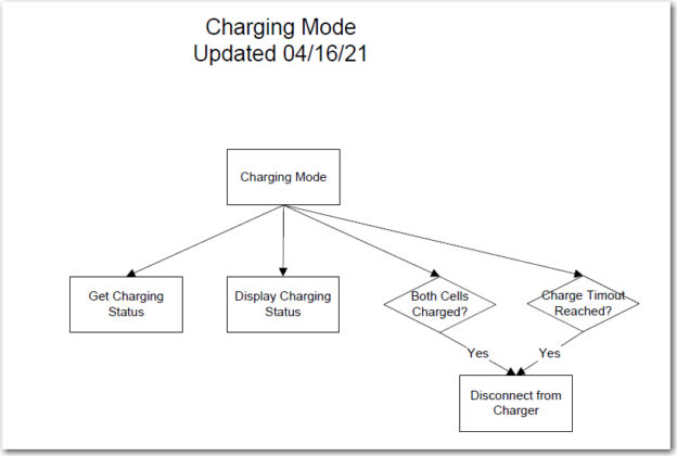
In my new strategy of eliminating all inner loops, the   ‘MonitorChargeUntilDone()’ function will no longer be used.  Instead,  the ‘Charge Mode’ block of the new software structure chart (shown below) will be implemented.
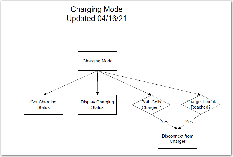
Updated Charge Mode Structure Chart Detail

This block will be executed on each pass through the loop() function, as long as the ‘Determine Op Mode’ block returns with the current mode set to ‘MODE_CHARGING’.  When/If the ‘Both Cells Charged’ or the ‘Charger Timeout’ reached ‘if’ statements return TRUE, then the ‘Disconnect’ function will be triggered, which will cause the robot to immediately disconnect and back away from the charging station.  This in turn will cause the ‘Determine Op Mode’ block to output a different mode value (assumed to be, but not necessarily ‘MODE_WALL_FOLLOWING’), and the appropriate portion of the overall structure diagram will be executed.

I’m away from my robot at the moment, at a bridge tournament in Gatlinburg, Tennessee, so I can’t immediately implement and test the above changes.  However, I will be back home next week and hope to have everything running by the end of May. If everything works out, I may have a fully functioning charge station operational by then, and a ‘more-or-less’ fully autonomous Wall-E2 robot.  It will be interesting to see what kind of trouble Wall-E2 can get into with the much longer run times that should be possible with autonomous charging capability.

Stay tuned!! 😉

Frank


Charging Station System Integration. Part III

Posted 15  April 2017

In my previous post on this subject, I described some IR homing tests with and without the overhead incandescent lights, and  the development of a ‘sunshade’ to block out enough of the IR energy from the overhead lamps to allow Wall-E2 to successfully home in on the IR beam from the charging station.  At the conclusion of that post, I had made a couple of successful runs using a temporary cardboard sunshade, and thought that a permanent sunshade would be all that I needed.

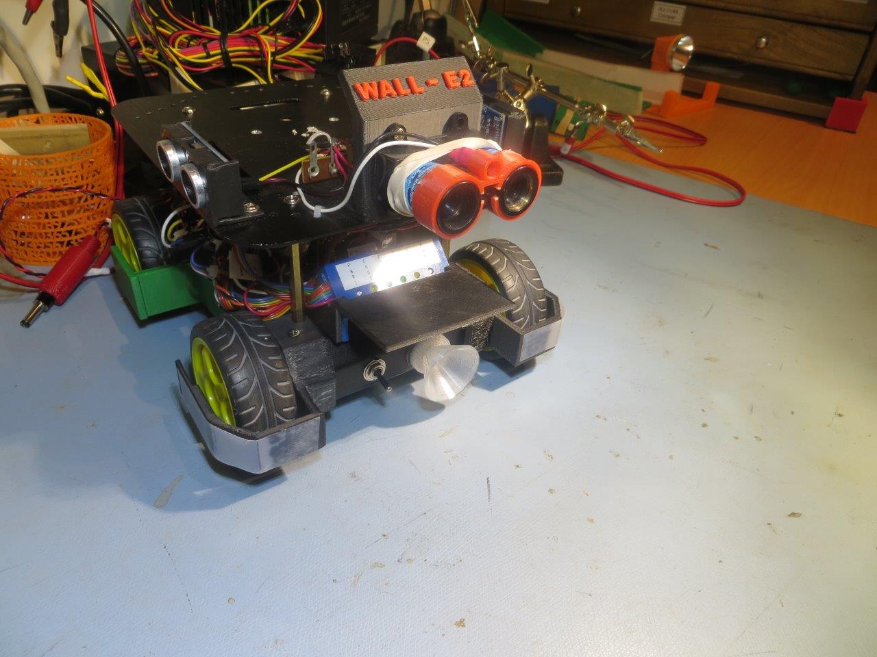
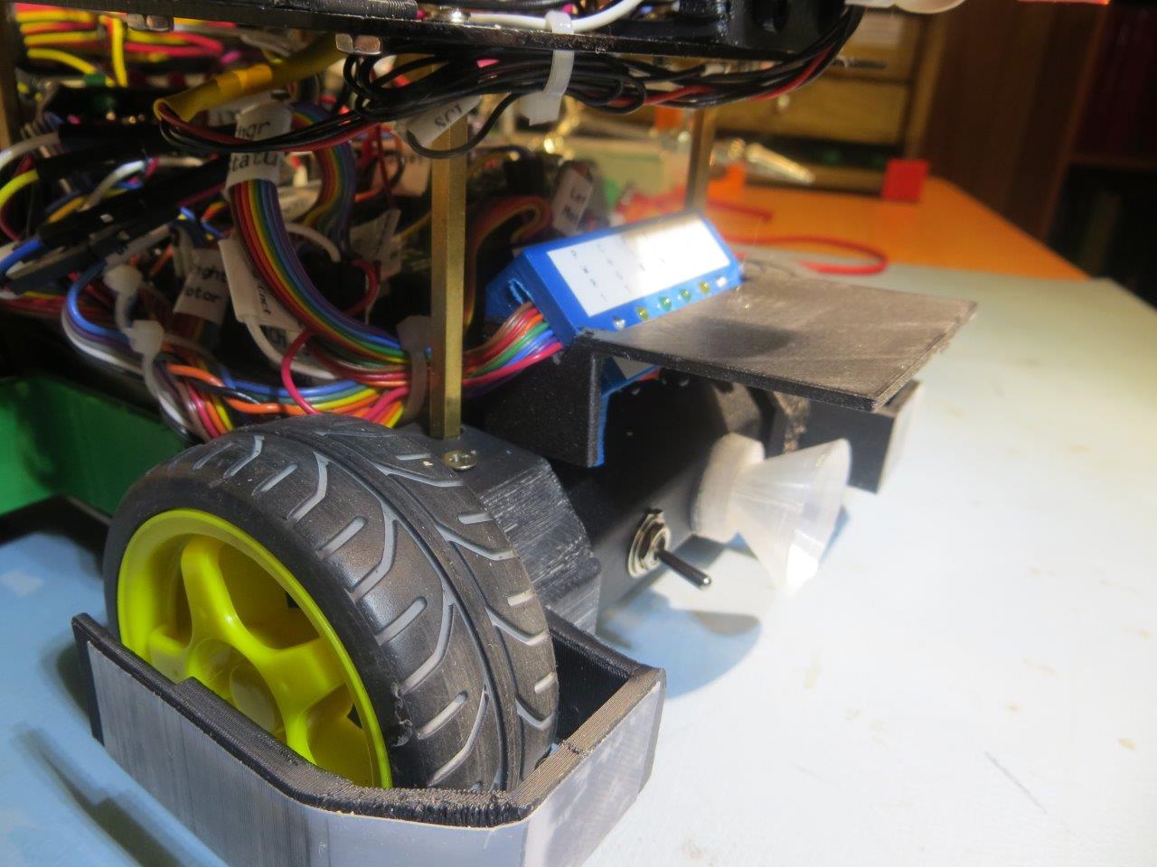
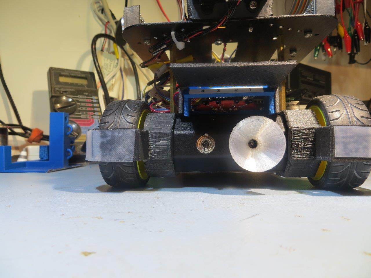
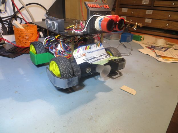
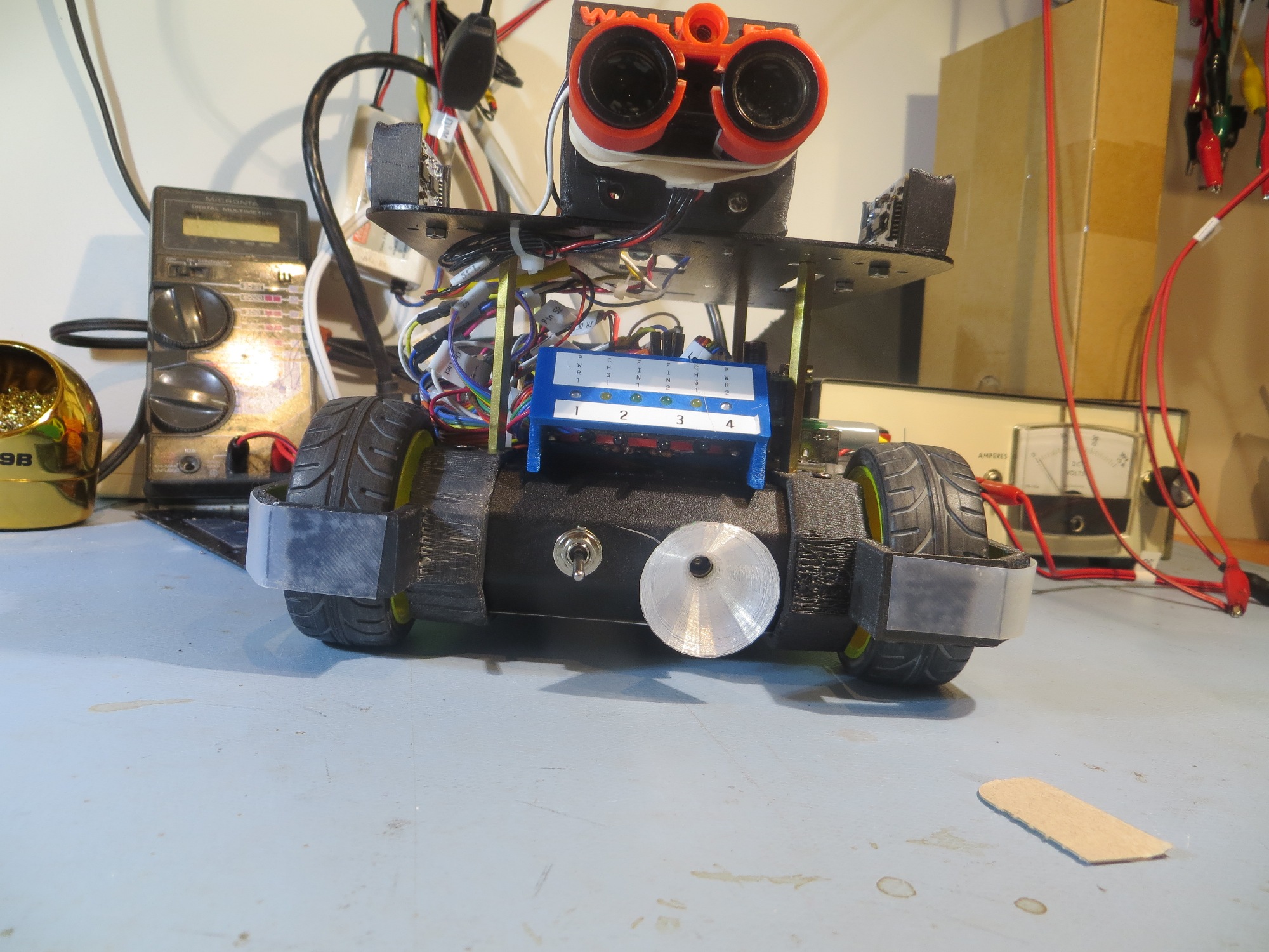
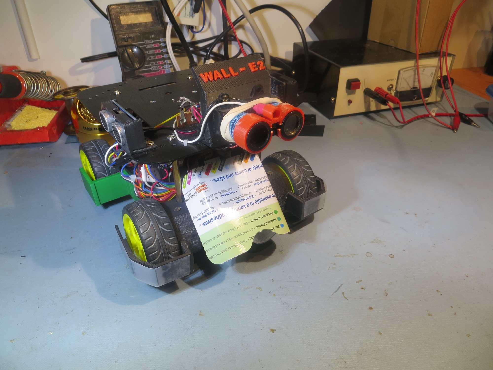
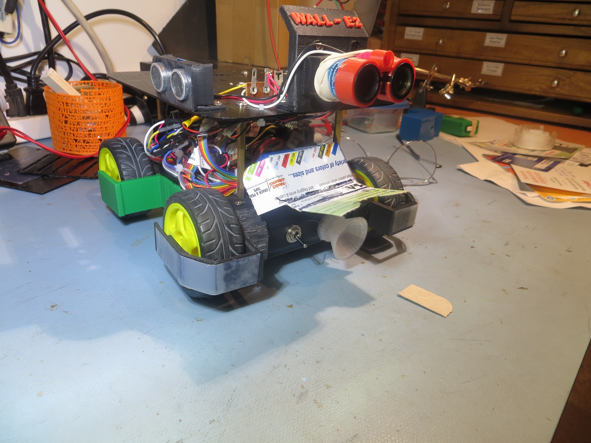
However, after installing the sunshade (shown below), I discovered that the homing performance in the presence of overhead IR lamps was marginal when the robot’s offset distance from the wall was more than about 50 cm.

Sunshade, oblique view

Sunshade, side view

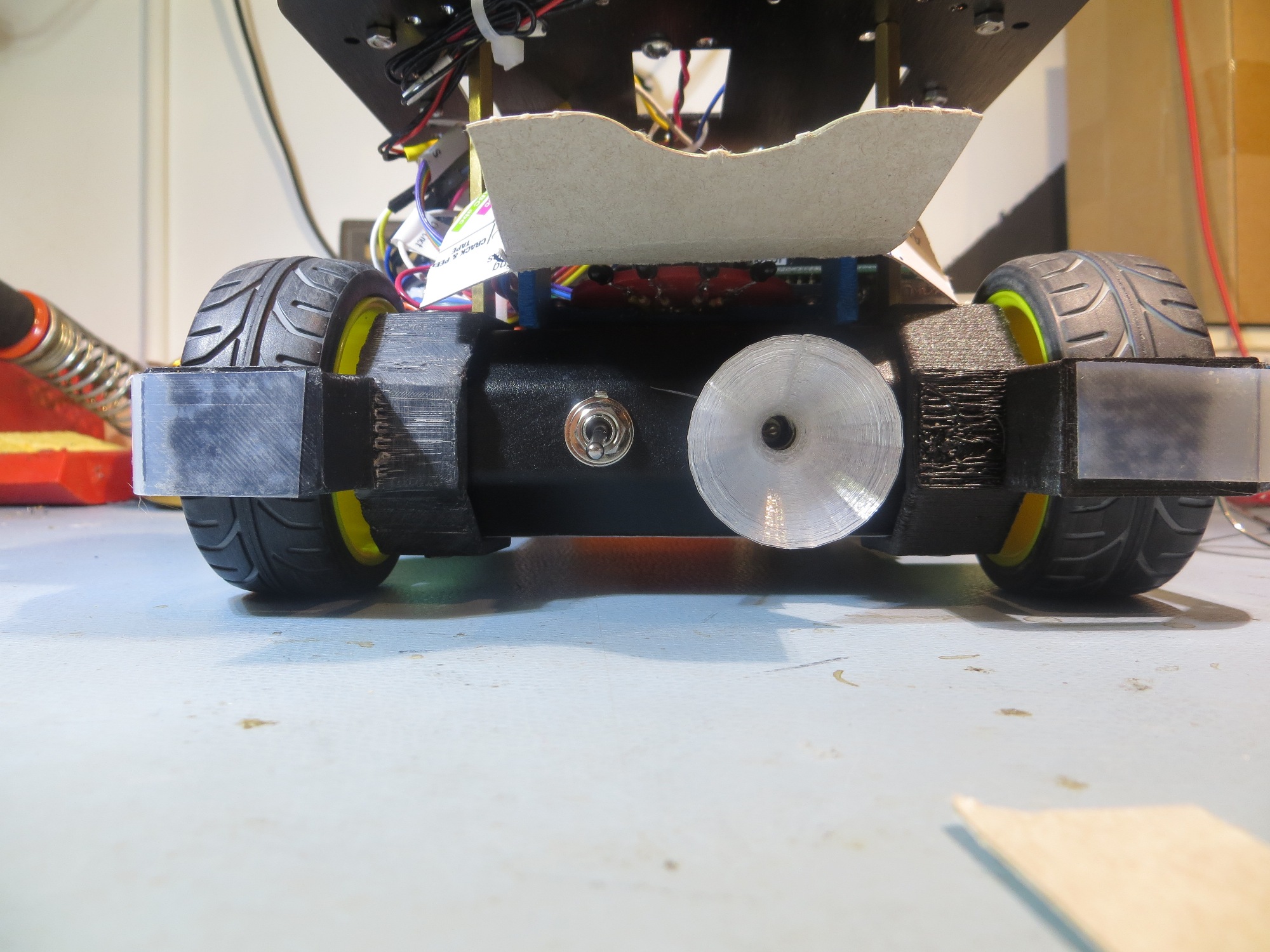
Sunshade, front view

Apparently  the IR interference was causing the robot to not respond to the IR beam until too close to miss the outer lead-in rail.  This issue was explored in an earlier post, but I have repeated the relevant drawings here as well.


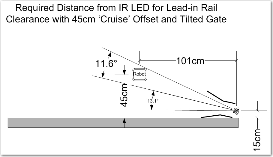
Tilted gate option. The tilt decreases the minimum required IR beam capture distance from about 1.7m to about 1.0m

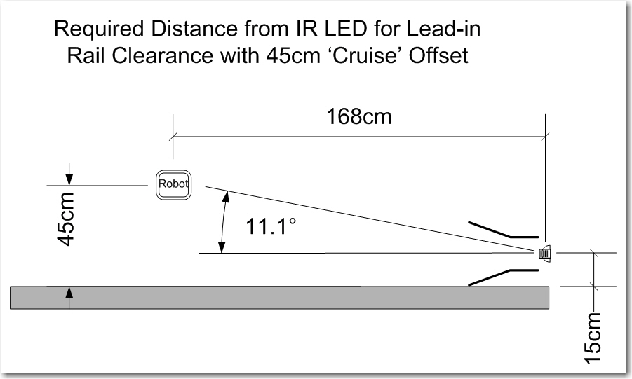
Capture parameters for the robot approaching a charging station

When the robot is ‘cruising’ at more than about 50 cm from the tracked wall,  the IR interference from the overhead lamps prevents the robot from acquiring the charging station IR beam until too late to avoid the outer lead-in rail, even in the 13 º tilted rail arrangement in the first drawing above.


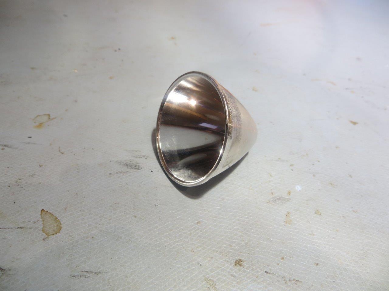
So, what to do?  I am already running the IR LED at close to the upper limit of the normal operating current, so I can’t significantly increase the IR beam intensity – at least not directly.  I can’t really increase the size of the ‘sunshade’ dramatically without also significantly affecting the IR beam detection performance.  What I really needed was a way of increasing the IR beam intensity  without increasing the LED current.  As it turns out, I spent over a decade as a research scientist at The Ohio State University ElectroScience Lab, where I helped design reflector antenna systems for spacecraft.  Spacecraft are power and weight limited, so anything that can be done to improve link margins without increasing weight and/or power is a  good thing, and it turns out you can do just that by using  well-designed reflector dishes to focus the microwave communications energy much like a flashlight. You get more power where you want it, but you don’t have to pay for it with more power input; the only ‘cost’ is the insignificant added weight of the reflector structure itself – almost free!  In any case, I needed something similar for my design, and I happened to have a small flashlight reflector hanging around from a previous project – maybe I could use that to focus and narrow the IR beam along the charging station centerline.

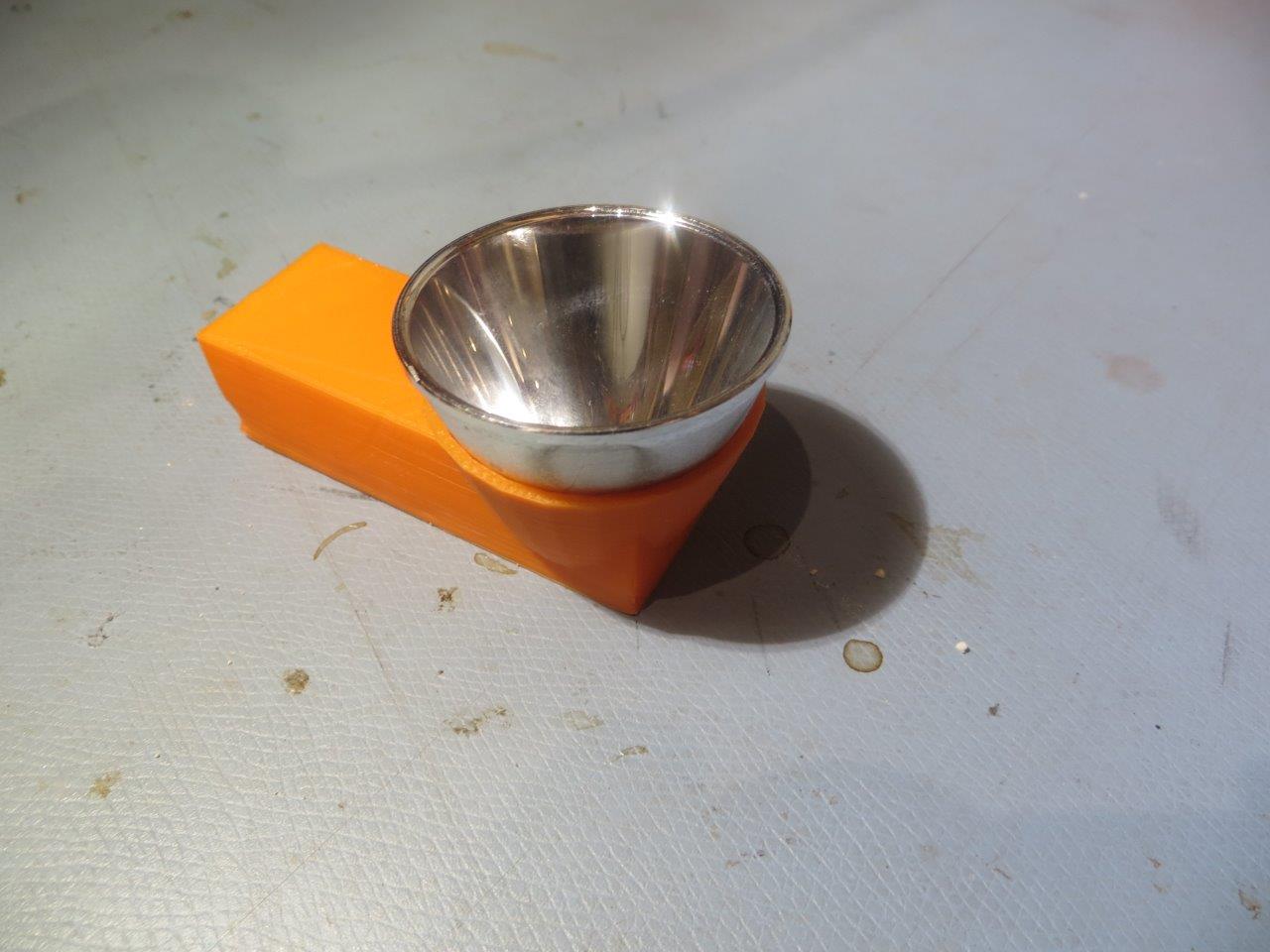
LED flashlight reflector

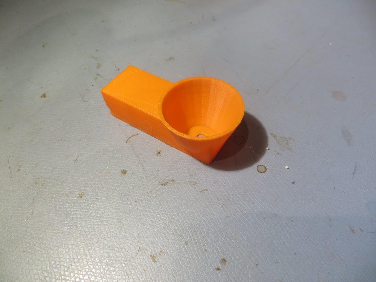
So, using my trusty PowerSpec PRO 3D printer and TinkerCad, I whipped up an experimental holder for the above reflector, as shown below

Experimental 3D-printed flashlight reflector holder

Reflector mounted on experimental holder

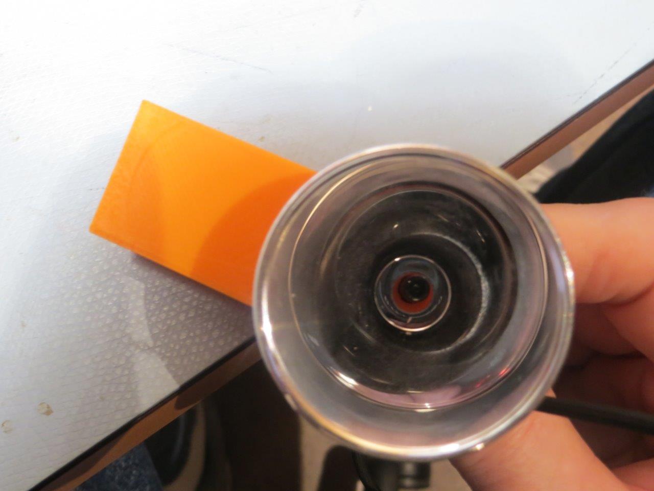
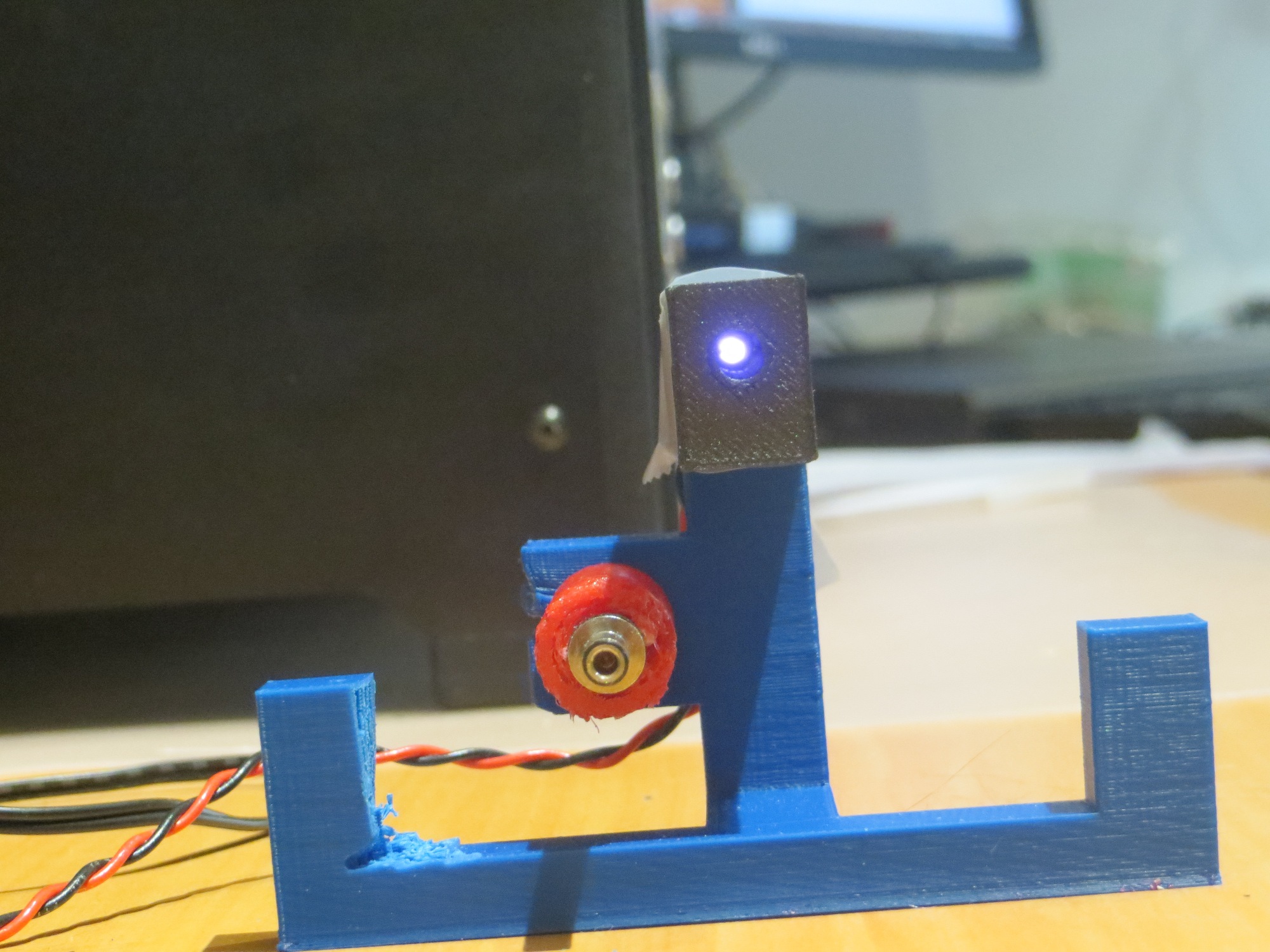
IR LED mounted on reflector

A couple of quick bench-top tests convinced me I was on the right track; At 1m separation between the IR LED/reflector combination and the robot, I was able to drive the robot’s phototransistors into saturation (i.e. an analog input reading of about 20 out of 1024 max), where before I was lucky to get it down to 100 or so.  However, this only happened when I got the LED positioned at the reflector focal point, which was tricky to do by hand, but not too bad for a first try!

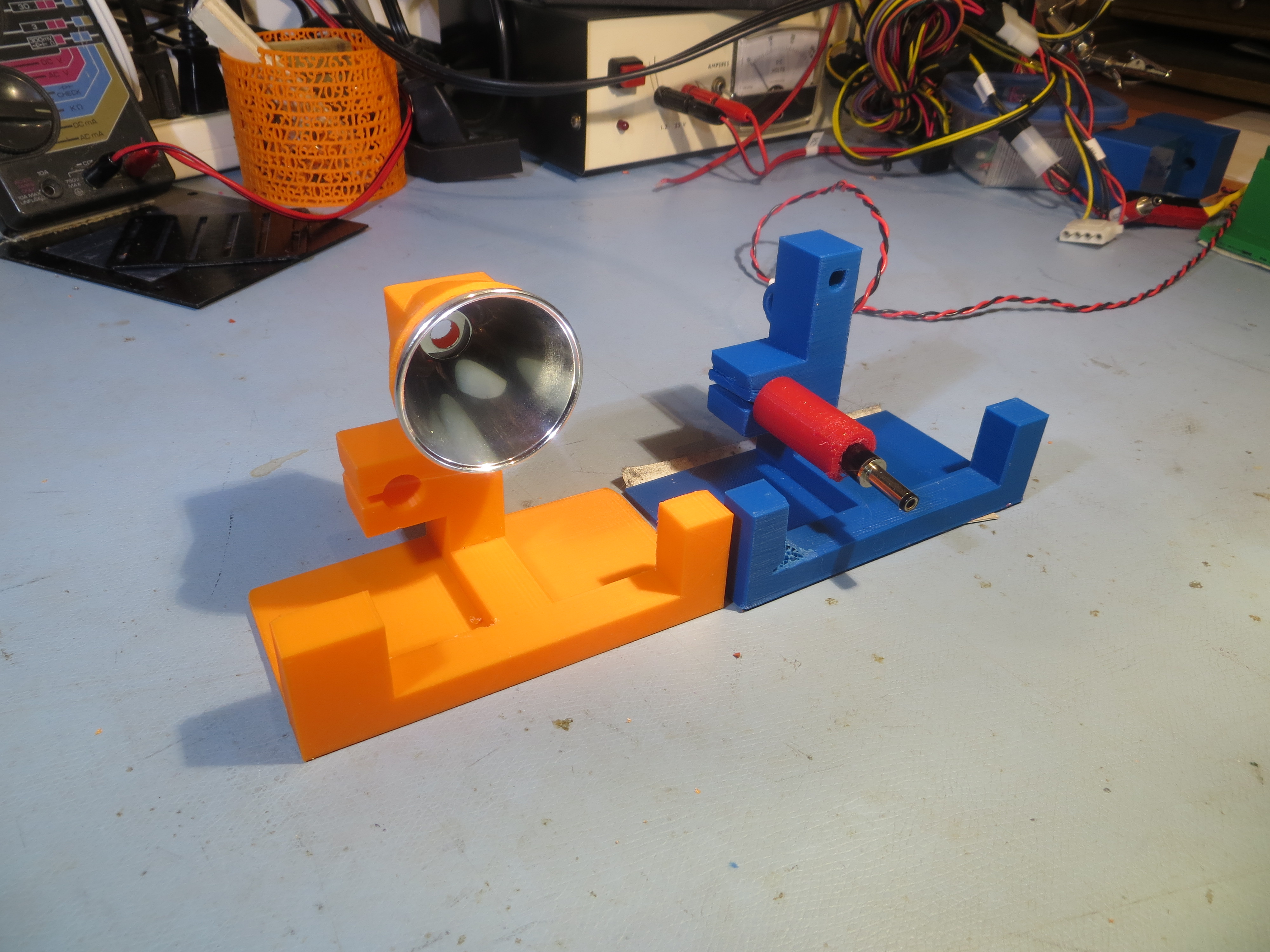
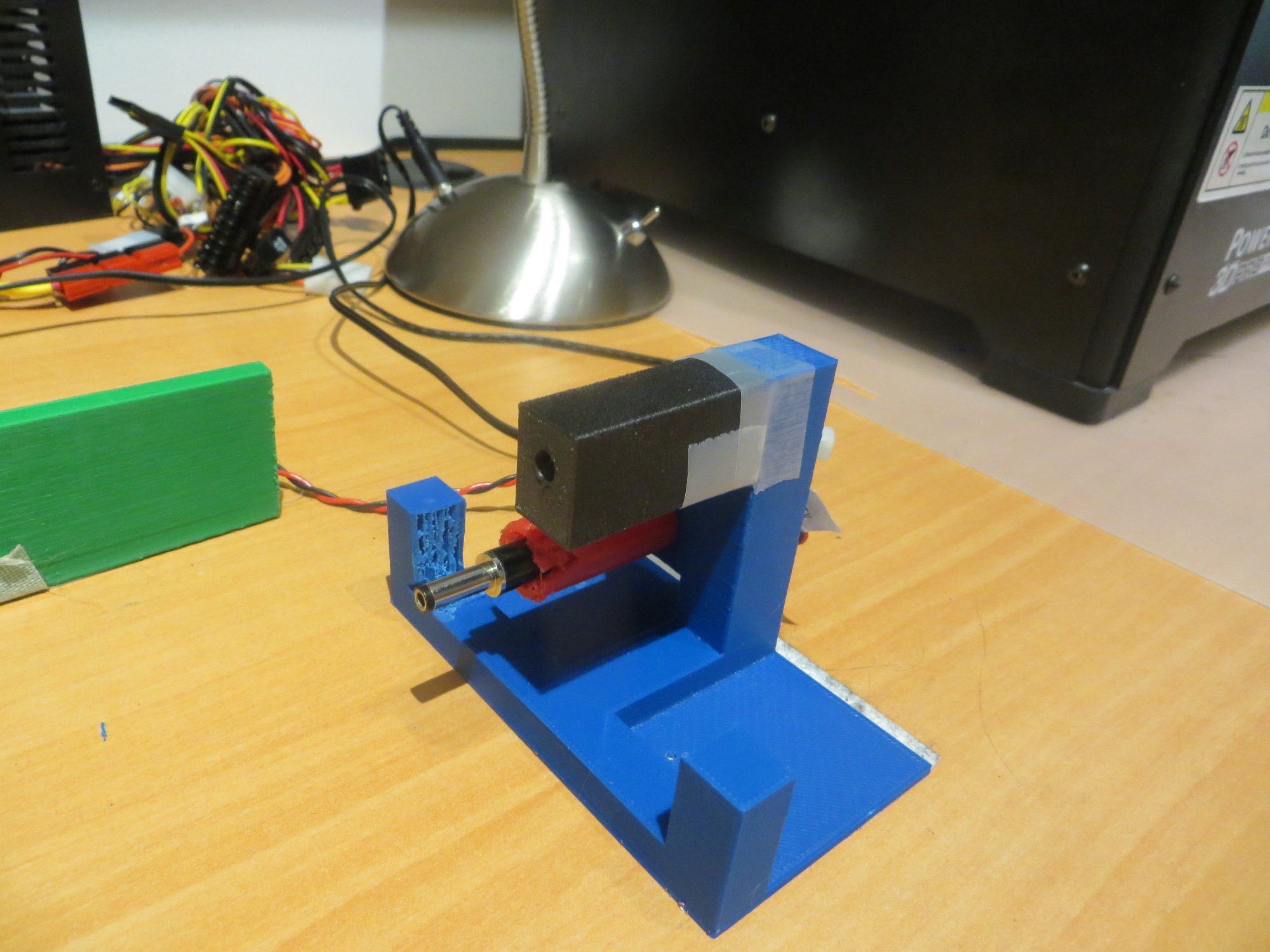
Next, I tried incorporating the reflector idea into the current charging station IR LED/charging probe fixture, as shown in the following photo. This was much closer to what I wanted, but it still was too difficult to get the IR LED positioned correctly, and this was made even more difficult by the fact that I literally could not see what I was doing – it’s IR after all!

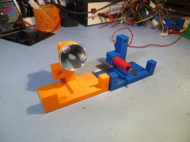
New reflector and old charging station fixture designs

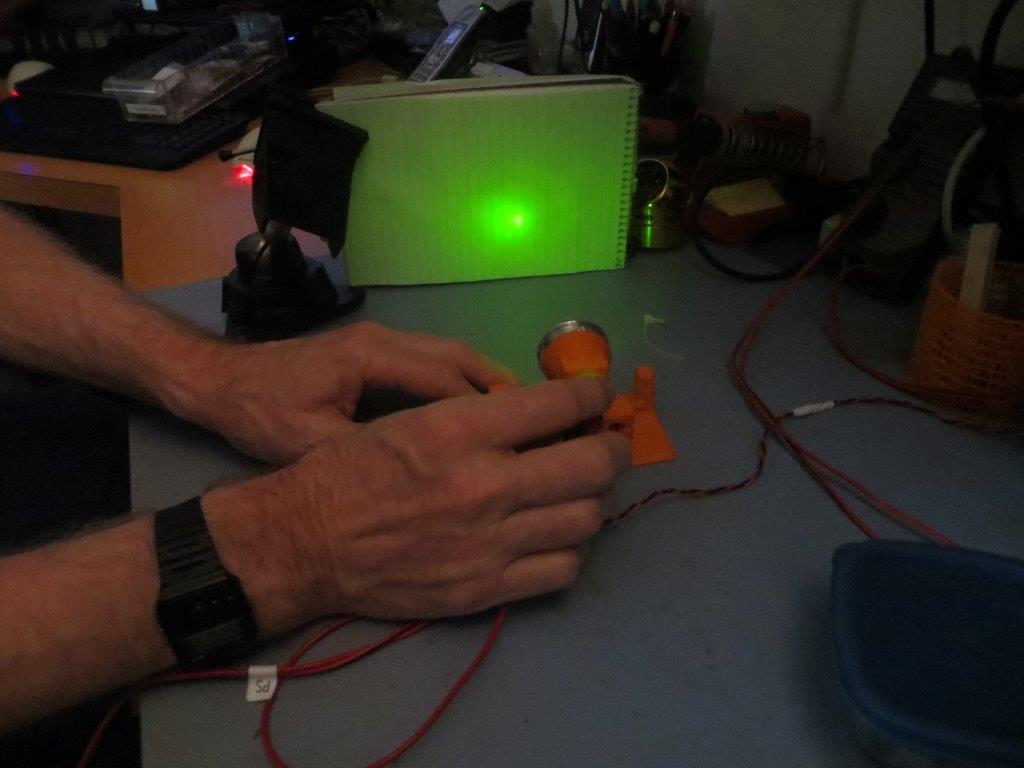
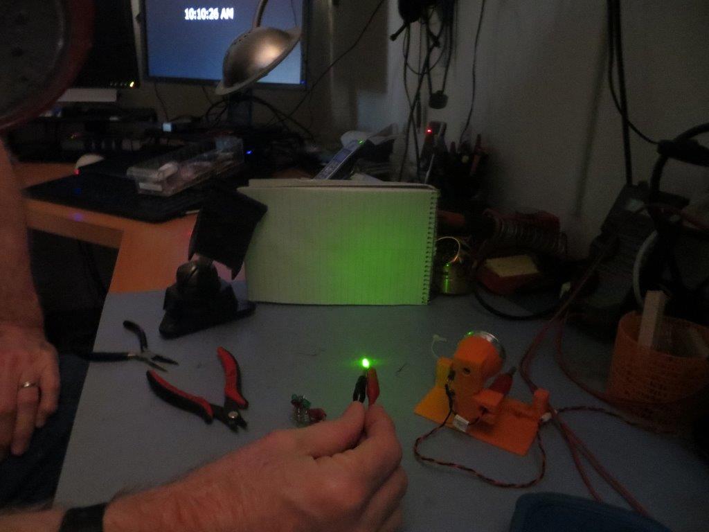
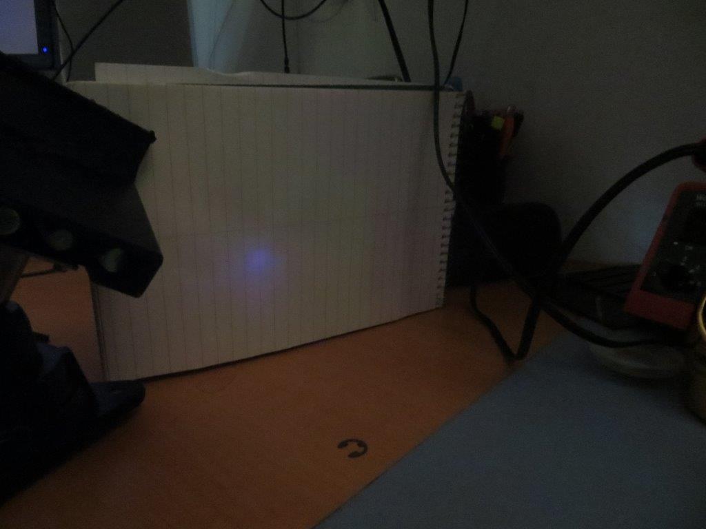
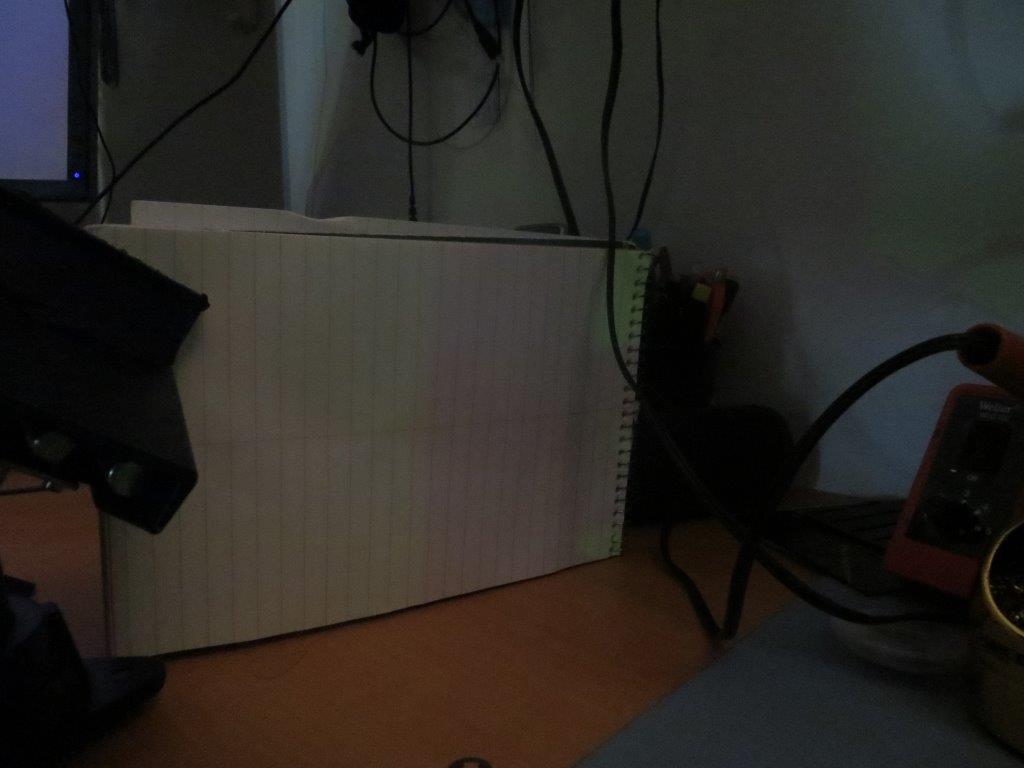
However, the reflector focusing performance should be (mostly) the same for IR and visible wavelengths, so I should be able to use a visible-wavelength LED for initial testing, at least.  So, I set up a small white screen 15-20 cm away from the reflector, and used a regular visible LED to investigate focus point position effects.  As the following photos show, the reflector makes quite a difference in energy density.

Green visible LED, hand-positioned near the focal point

Pattern without the reflector

Next, I used my Canon PowerShot SX260HS digital camera as an IR visualizer so I could see the IR beam pattern. As shown below, the reflector does an excellent job of focusing the available IR energy into a tight beam

IR beam visualized using my Canon PowerShot SX260HS digital camera

IR LED, without reflector

Next, I made another version of the reflector holder, but this time with a way of mounting the LED more firmly at (or as near as I could eyeball) the reflector focal point.

Reflector holder modified for more accurate LED mounting

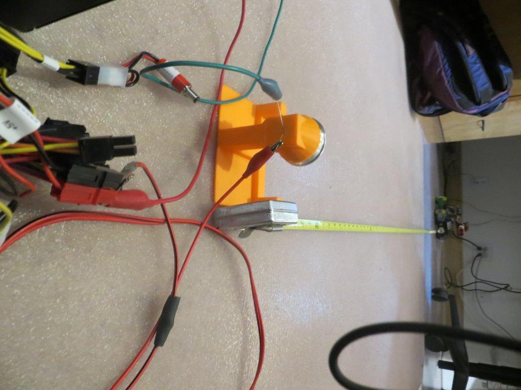
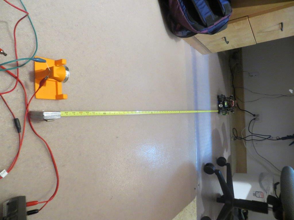
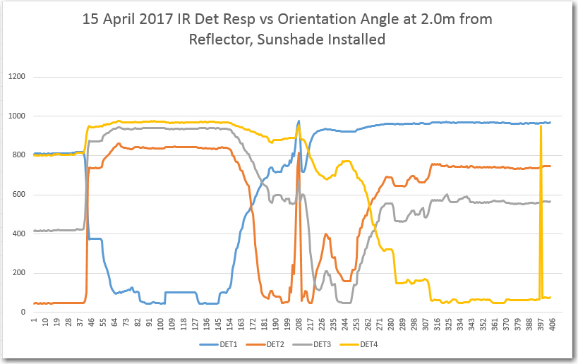
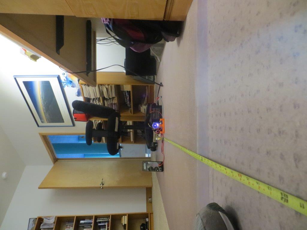
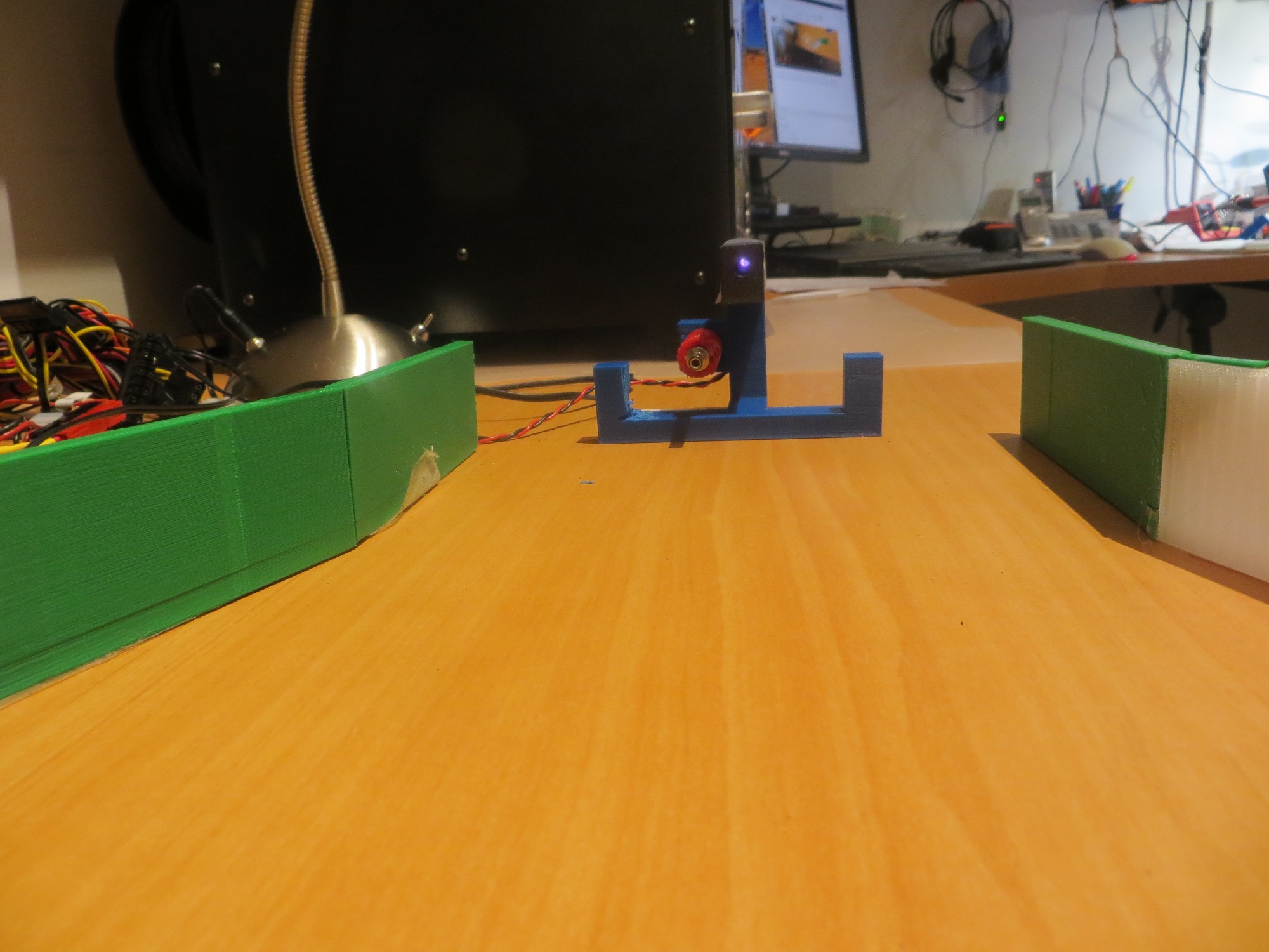
With this modification, I was able to get pretty good focusing without having to fiddle with the LED location, so I set up some range tests on the floor of my lab.  With LED overhead lighting (not incandescent), I was able to get excellent homing performance all the way out to 2m, as shown in the following photos and plots

Range testing the IR reflector in the lab. Distance 2m

IR Detector response vs orientation at 2m from reflector, in the lab

IR reflector beam pattern at 2m, visualized using digital CCD camera

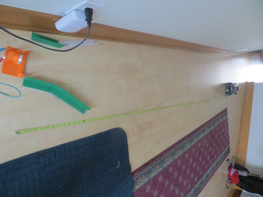
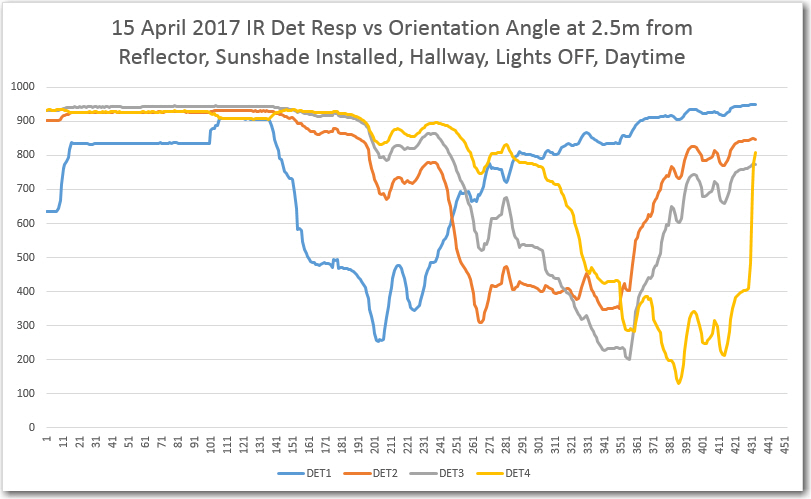
After this, I decided to try my luck again out in our entry hallway, with the dreaded IR interference from the overhead lighting and/or sunlight.   I installed the lead-in rails in the ’tilted’ arrangement, and then performed a response vs orientation test with the robot situated about 2.5m from the IR LED/reflector assembly, in natural daylight illumination with the overhead incandescents OFF.  This produced the curves shown in the plot below.

Robot response vs orientation test setup, 2.5 m from tilted lead-in rails & LED/reflector assembly

IR detector response vs orientation test, 2.5 m from IR LED/Reflector assembly

In  the above Excel plot, the individual detector response minimums can be clearly seen, with minimum values in the 200-300 range, and off-axis responses in the 800-1000 range.  This should be more than enough for successful IR homing.

After seeing these positive responses, I ran some homing tests starting from this same general position.  In each run, the robot started off tracking the right-hand wall at about 50 cm  offset.  One run was in daylight with the overhead lights OFF, and another was in daylight with the overhead lights ON.  As can be seen in the videos below.

Both of the above test runs were successful.  The robot started homing on the IR beam almost immediately, and was successfully captured by the lead-in rails.

So, it is clear the reflector idea is a winner – it allows the robot to detect and home in on the IR beam from far enough away to not miss the capture aperture, even in the presence of IR interference from daylight  and/or  overhead incandescent lighting.

Next step – reprint the IR LED reflector holder with the charging probe holder included (I managed to leave it out of the model the last time), and verify that the robot will indeed connect and start charging.


Charging Station System Integration. Part II

Posted 07 April 2017

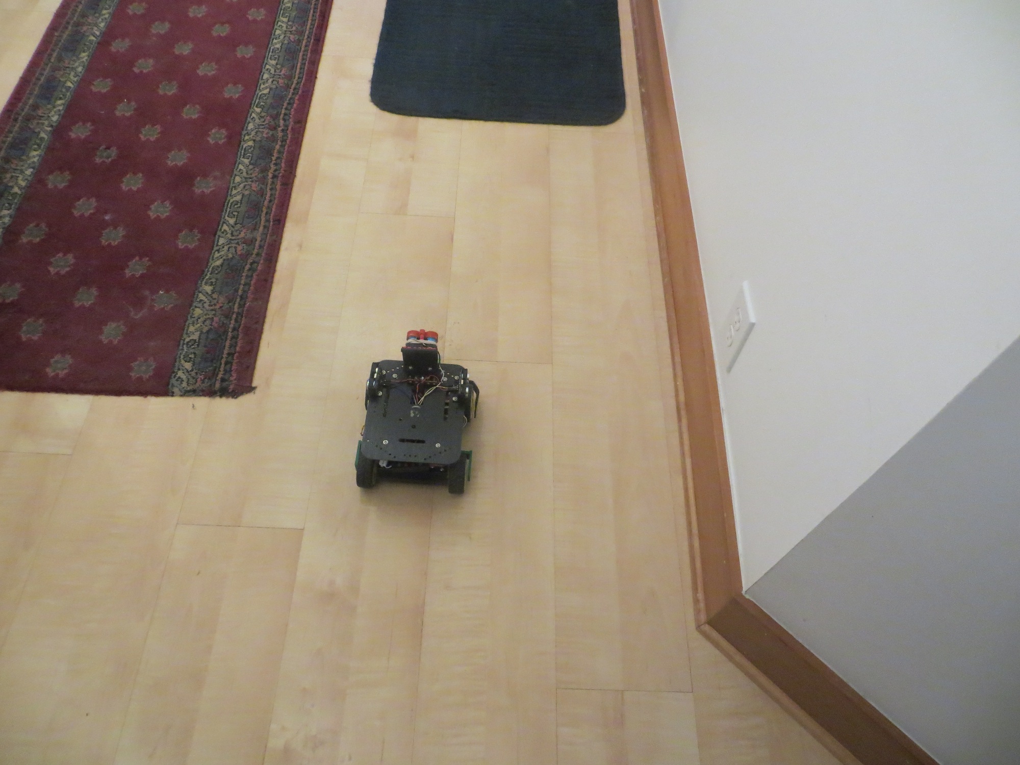
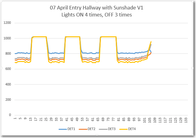
After getting the wall-following mode re-implemented in the ‘new-improved’ Wall-E2 operating system, I re-enabled the IR homing part of the code, only to discover that Wall-E2 thought it could see the IR homing beam  everywhere, in the atrium, even though the IR homing LED wasn’t even in the room (and was turned OFF, besides)!  This didn’t make a whole lot of sense, until I realized Wall-E2’s sensors were ‘seeing’ IR from the overhead floodlamps.  I confirmed this by having my ‘lovely assistant’ wife turn the atrium lights on & off and monitoring the detector outputs.  Same thing for the entry hallway (see data below)

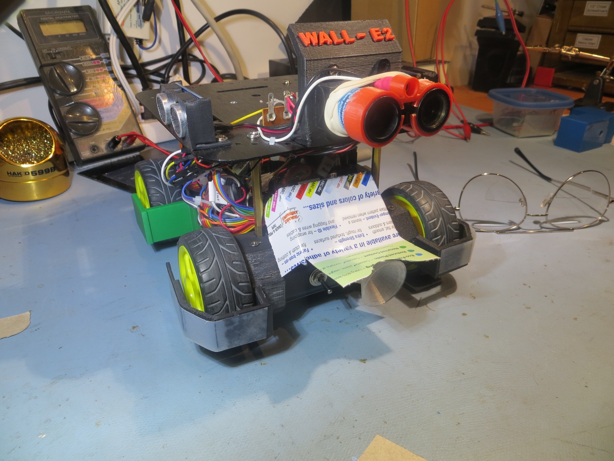
I thought I had solved this problem way back when I first started working with the IR detection/homing idea back in October of last  year.  In that initial post  where I investigated  the  OSEPP IR Light Follower’, I found I had to turn OFF the LED track lights in my lab in order to avoid swamping the detector array.  Over the next month or so this project evolved into a custom designed array of  Oshram SFH309FA-4 phototransistors (see  http://gfpbridge.com/2016/11/ir-light-follower-wall-e2-part-vi/), and as part of this I discovered that the Oshram devices weren’t at all sensitive to the LED track lighting in my lab.  From this I concluded (erroneously as it now turns out!) that I didn’t need a ‘sunshade’ at all, which allowed for a much simpler installation on the robot (see  http://gfpbridge.com/2016/11/ir-light-follower-wall-e2-part-vii/).  Finally, when this module was transferred from the 3-wheel test bed to the Wall-E2 and combined with the charging status display panel, we arrived at the ‘final’ arrangement shown in the following photo

IR detector module (red) shown beneath charging status display panel (blue)

This worked great for all my in-lab IR homing tests with my all-LED overhead track lighting, but as soon as I started testing out in the rest of the house, the overhead incandescent and halogen lamps swamped out the detectors. So, it was back to the drawing board – again :-(.

The first thing I did was to confirm that the IR detectors were indeed getting swamped by the overhead lighting, and that it was possible to prevent this by some sort of shielding.  I started with a wrap-around cardboard shield that completely covered the IR detector module, as shown below, and placed the robot on the floor of the entry hallway in a normal ‘wall-following’ position

Sunshade V0. Not very practical, but does set the baseline for the rest of the tests

Test position for 07 April 2017 sunshade tests


With this setup, Wall-E2 was pretty much deaf to the overhead lamps, showing no reaction to cycling the lights.  Of course, this configuration would also completely prevent it from detecting the charging station IR beam, but….

Next I modified the above V0 cover to allow a bit more visibility, as shown below:

Sunshade V1 oblique view

Sunshade V1 front view

This version is still a bit too restrictive for normal IR beam detection/homing, but was worth a shot for testing purposes.  With this setup, the overhead lighting  is noticeable, as shown below.

Sunshade V1 at sunshade test position. Lights ON four times for 5, 5, 5 and 10 sec

As can be seen from the plot, the V1 sunshade responds to the overhead lamp IR with an average A/D reading about 700 out of 1024.

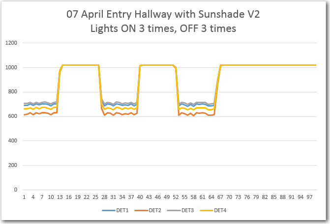
Next, I modified  the sunshade again so that it would just allow the IR detector module to ‘see’ straight ahead, on the theory that that would be the minimum requirement for successful IR beam detection/homing.  With this setup, the overhead lamp response was stronger, but still not completely overbearing;  the IR detector response to the overhead lights averages A/D values of about 600 out of 1024.

Sunshade V2 oblique view

Sunshade V2 front view.  Note IR detectors visible from directly in front

IR detector response to overhead lamps. ON three times for 5 sec each

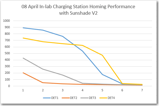
When I ran a homing test  with the V2 sunshade in my lab (with LED overheads, not incandescent), the robot homed successfully from about 1 m away, with the following IR detector/homing performance

In-lab (LED overhead lighting) charging station homing performance with V2 sunshade

In the above homing test, the IR detector values started out at approximately 900, 200, 450 and 750, respectively.  This means I could set the IR beam detection threshold at, say, 400 and still have a 200-count noise margin in both directions (200 down from the overhead IR flooding value, and 200 up from the typical 1-meter IR beam intensity).  From the movie it is obvious that the minimum IR reading is switching back and forth between at least two detectors, so I think it is safe to say that IR homing would occur even in the presence of a 600 unit noise level, as the 200 or lower reading switched between detectors.

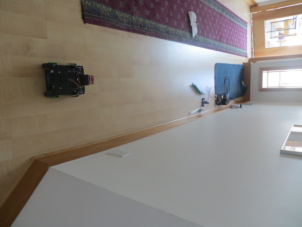
Next, I moved the charging station into the entry hall so I could test IR homing performance with the overhead lights on and off.  My prediction was that Wall-E2 should be able to home successfully in both cases.  For the test, the charging station lead-in rails were oriented in the preferred ’tilted’ orientation, as that should give the best homing performance, as shown in the photos below:

Hallway IR homing test setup

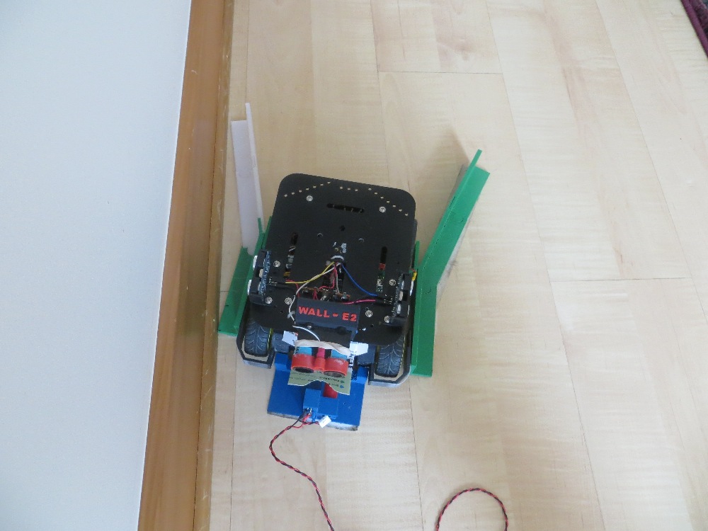
Robot shown in captured position. Note lead-in rail ’tilt’ relative to the wall

I made three runs; Lights ON, lights OFF, and Lights ON, as shown in the three video clips below:


As can be seen in the videos, Wall-E2 successfully homed to the charging station with the overhead lights OFF, but not with them ON – bummer!

So, further testing will be required to determine the particulars of the two failed runs, and what – if anything – can be done about it.

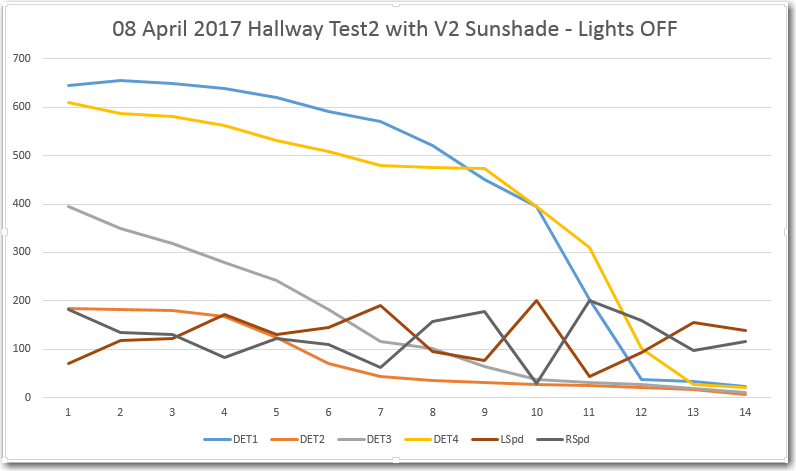
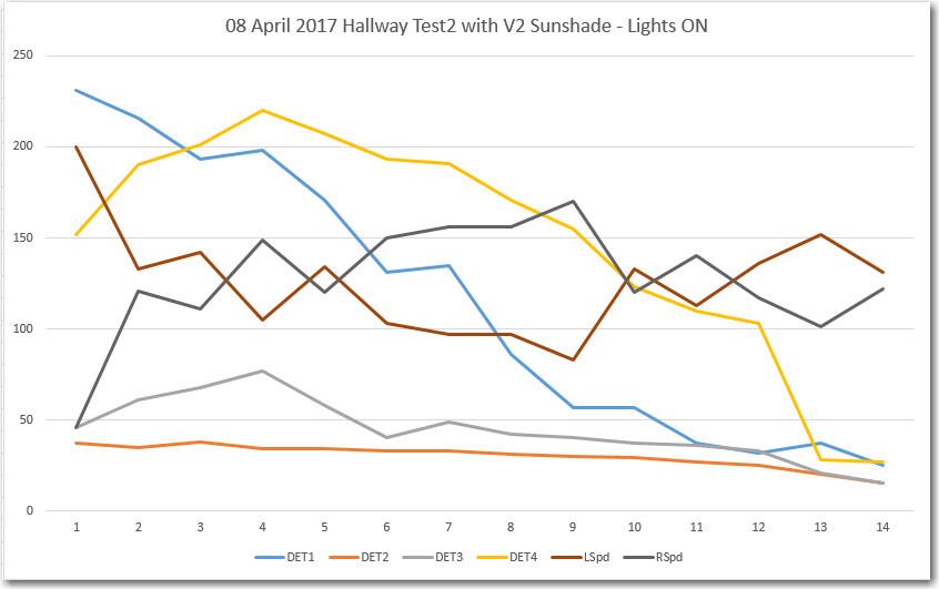
After moving my laptop  out into the hallway so I could capture telemetry from the robot while also filming the runs, and checking everything out, I made two successful IR homing runs – one with the overhead lights ON, and another one with them OFF.  I captured telemetry from both runs, and was clearly able to distinguish between the lights ON and OFF scenarios.  The videos and the telemetry plots are shown below:

08 April 2017 Hallway Test2 with V2 Sunshade – Lights OFF

08 April 2017 Hallway Test2 with V2 Sunshade – Lights ON

From the above plots, the lights ON & OFF conditions are readily recognizable.  In the ‘OFF’ condition, the ‘background noise’ is at about 600-700, and the IR beam is at 100-200.  In the ‘ON’ case, the noise level is higher (lower count), at about 150-250, but the IR beam is lower too – around 50-150.  I guess this makes some sort of sense, as the IR energy from the charging station beam is a separate, additive source relative to the overhead lighting.  Also, both plots show good motor response curves – the left & right motor speeds are obviously being adjusted rapidly in response to IR detector changes.

So, at this point I’m pretty convinced that the V2 sunshade is working, so I plan to print up a permanent version that will (hopefully) simply slide on to the front of the existing charge status display panel.

Stay tuned!

Frank


Charging Station System Integration – Part I

Posted 29 March 2017

In my last ‘Charging Station’ post, I had arrived at the point where Wall-E2 could reliably home in on an IR beam, dock with the charging station power probe, switch from ‘run’ to ‘charge’ mode, and then after a 10-second delay (for testing purposes only – the ‘production’ version will wait for  the ‘Finished’ signal from both battery stacks before disconnecting) disconnect and back away from the charging station.  At this point, it is time to start the process of incorporating Wall-E2’s new charging super powers  into the overall system design  (or maybe integrating the overall system design with Wall-E2’s new charging super powers).

In my 11 March 2017  ‘Charging Station Design, Part X‘ post, I described what I thought were the major tasks remaining,  as follows:

  1. Reconnect and test the LIDAR and ping sensor hardware; this will be required to test wall-following and the charge station avoidance sub-mode
  2. Reprint the charging station fixture with 5mm more height
  3. Set up the full lead-in rail arrangement and confirm proper homing/engagement, along with proper dis-engagement, and proper avoidance when the battery isn’t low.
  4. re-implement and test the wall-following code in the new structure, as MODE_WALLFOLLOW.  This  should be just a bunch of cut-and-paste operations.
  5. test the various normal’ state transitions; wall-follow to IR homing to charge monitoring to wall-following
  6. test the wall-follow to IR homing to charge station avoidance transition.
  7. fully test the end-of-charge scenario.

Of the above tasks, the first three items are  essentially complete;  It is now time to address the last 4 items, starting with re-implementing the wall-following feature as part of the new software structure.  Contrary to my original thoughts, I no longer expect this to be a ‘bunch of cut-and-paste operations’ as my understanding of the overall system has improved considerably since I started the charging station work some four months ago.  Instead, I plan to start with the software structure proposed in my Wall-E2 Operating Mode Review post from 06 March 2017, as shown below:

Loader Loading...
EAD Logo Taking too long?

Reload Reload document
| Open Open in new tab

Download

The wall tracking structure is actually pretty simple, with the magic occurring in the details of the algorithm for tracking the selected wall using the appropriate ping sensor.  The current tracking algorithm is essentially a hand-coded version of a PID engine, with PID = (0,0, K), where K is a ‘MOTOR_SPEED_ADJ_FACTOR (currently set to 40).  Here’s the relevant code

LSPDn = LSPDn-1 + K * (Dn. Dn-1); RSPDn = RSPDn-1 – K * (Dn. Dn-1)

Based on the experience gained from using the PID engine for IR homing, I’m fairly confident it should work for wall tracking as well.  However, using the PID engine requires that a target setpoint be defined – in the case of wall tracking this would be a target offset distance from the wall being tracked.  In the current non-PID algorithm, this isn’t required – the robot simply tries to keep the distance constant, with no regard to the actual value.  I *think* I can handle this by dynamically setting the PID target value to the smaller of the initial left/right ping values  when the robot first enters wall tracking mode.  We’ll see….

April 05 2017 Update

I reconnected the LIDAR and sonar sensors, and re-implemented the wall-following code in the MODE_WALLFOLLOW case block of the new software structure.  I decided to stay with the homebrew tracking algorithm at the present, not wishing to introduce any more new variables than necessary.  To test the new arrangement, I made  some wall-tracking runs in our atrium, as shown in the following video.

And here is a screenshot of the plot of the relevant wall-following telemetry data

Relevant telemetry data from the first wall tracking test in the atrium

As can be seen, the robot tracks the right-hand wall pretty faithfully at a pretty constant distance (about 45-50 cm in this case).  From my earlier efforts testing with  IR homing to the  charging station  I showed that the robot would have to capture the IR beam at about 1.7  m out with the charging station lead-in rails aligned parallel to the wall, or about 1 m out with the rails angled away, in order to be successfully captured by the lead-in rails.  Now that I have wall-following re-integrated into the operating system, the next step will be the fifth item above, namely “test the various normal’ state transitions; wall-follow to IR homing to charge monitoring to wall-following”

Stay tuned,

Frank


PowerSpec 3D PRO Build Plate LED Lamps

Posted 03 April 2017

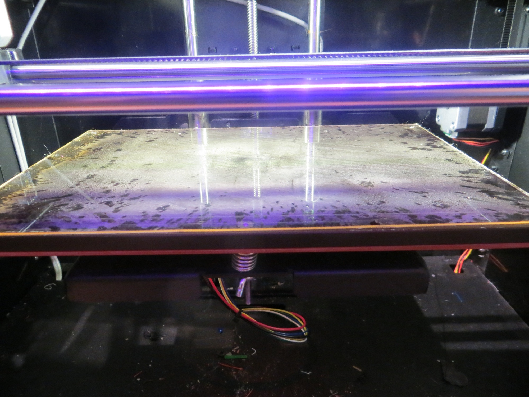
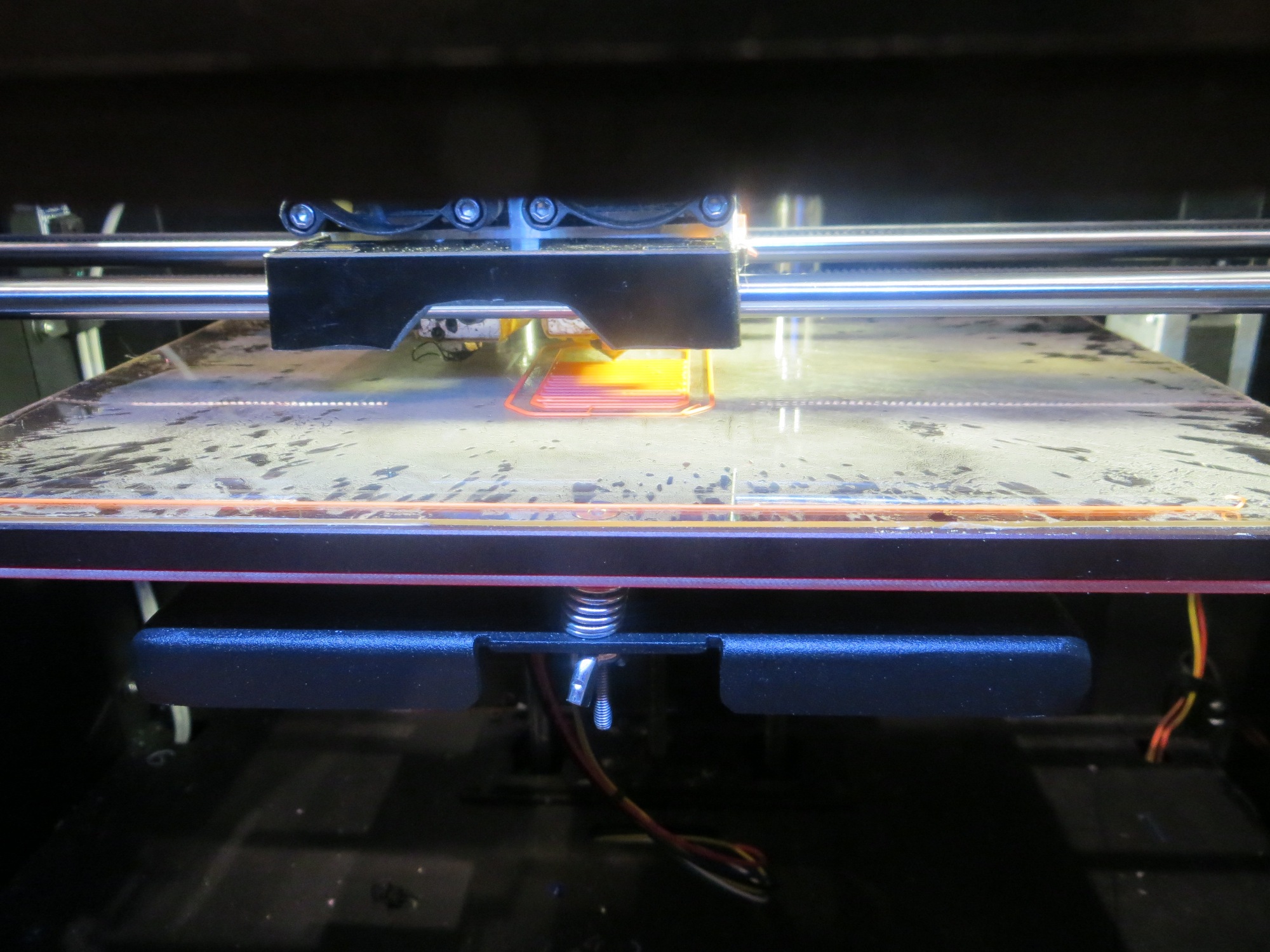
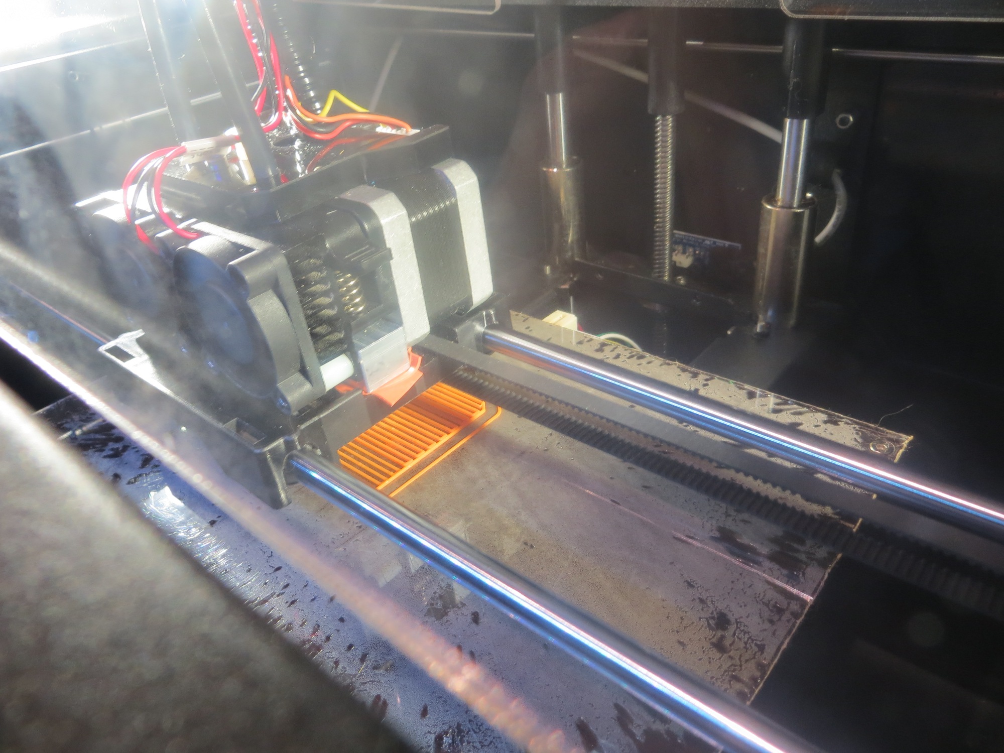
In the year or so since I started printing with my trusty PowerSpec 3D PRO (Microcenter clone of the FlashForge Creator PRO), I have struggled to see what was happening in the first few layers of problem prints.  The extruder/feed motor assembly is so big that it blocks  most of the sight line to the build surface.  What is left is a very shallow viewing angle, which is mostly shadowed by the print assembly.  Over time, I have found that hanging one of my goose-neck LED bench lamps over the top edge of the cabinet on either the left or the right side gave me a much better view – the restricted viewing angle was unchanged, but a  lot more light was thrown on the subject, literally.  However, this was an inelegant solution to say the least, as the lamp was apt to fall off the printer at the most inopportune times.

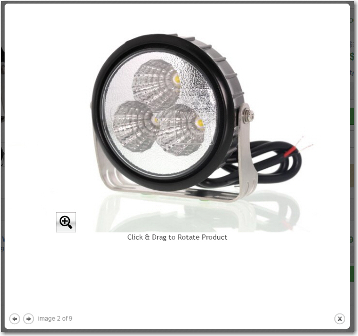
As usual, I kept thinking of ways to improve this situation, and finally came up with the idea of seeing if I could find some small LED work lights that I could permanently attach to the printer.  After some Googling around, I came up with a  2-lamp LED Auxiliary Light Kit (p/n DRL-CW3-SM-9) offered by superbrightleds.com  for $24.95/pair – nice!

DRL-NW3-SM 12-24V 9W Auxiliary LED Light Kit (2 lamps)

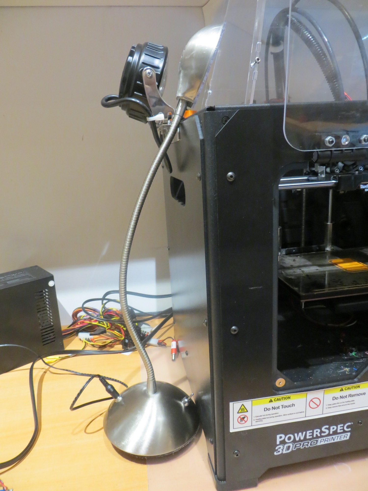
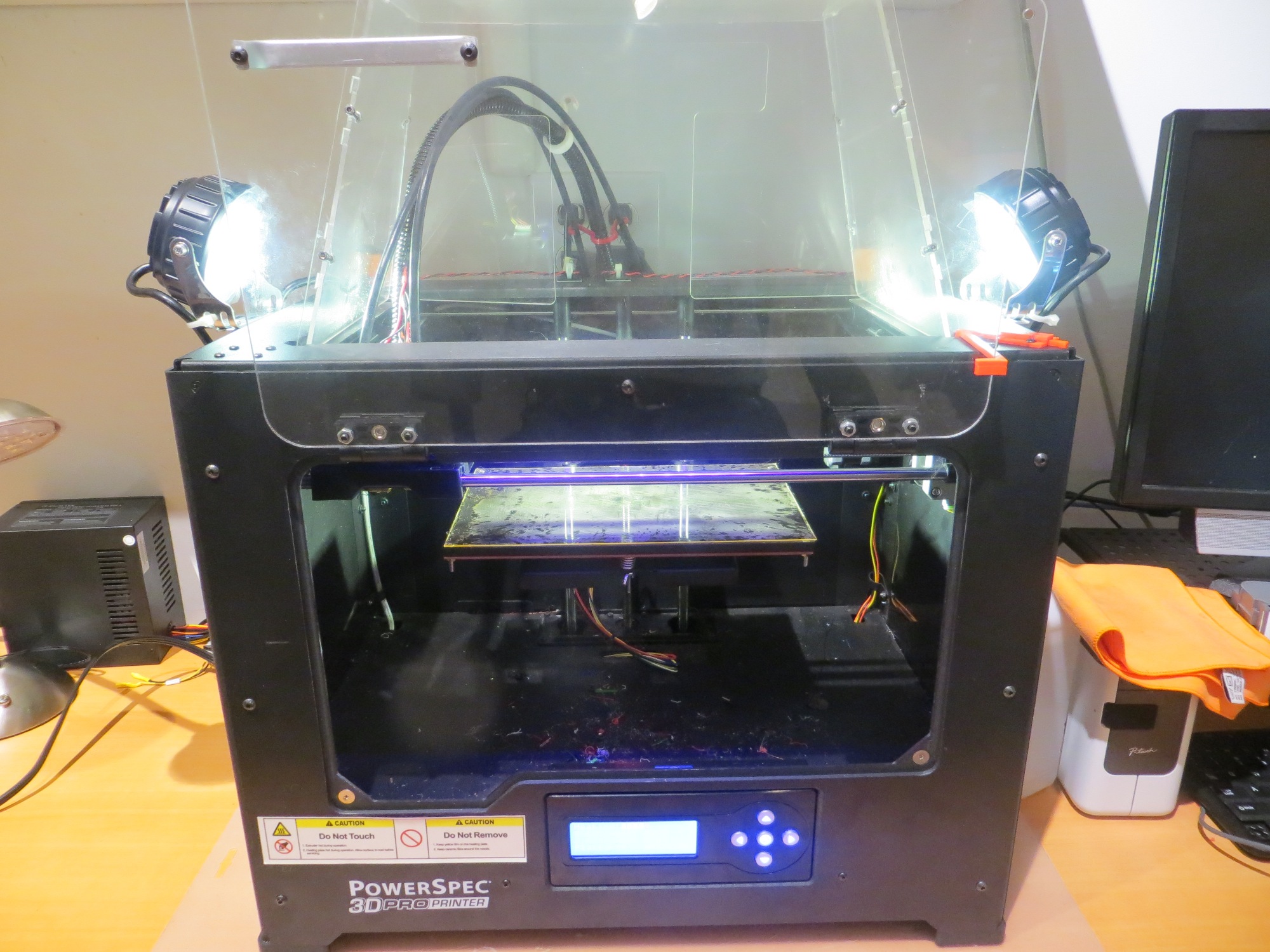
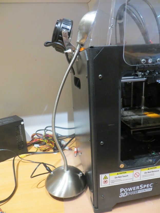
After some fiddling around and some goofs, I arrived at an arrangement I liked.  The lamps are mounted at the top of the cabinet and are pointed down so they illuminate the entire build surface, but are physically offset enough so the plastic top closure assembly can still be removed and put back on without problems (this was one of the goofs – the first arrangement I tried made removing/replacing this piece very tedious).  The shots below show the setup.

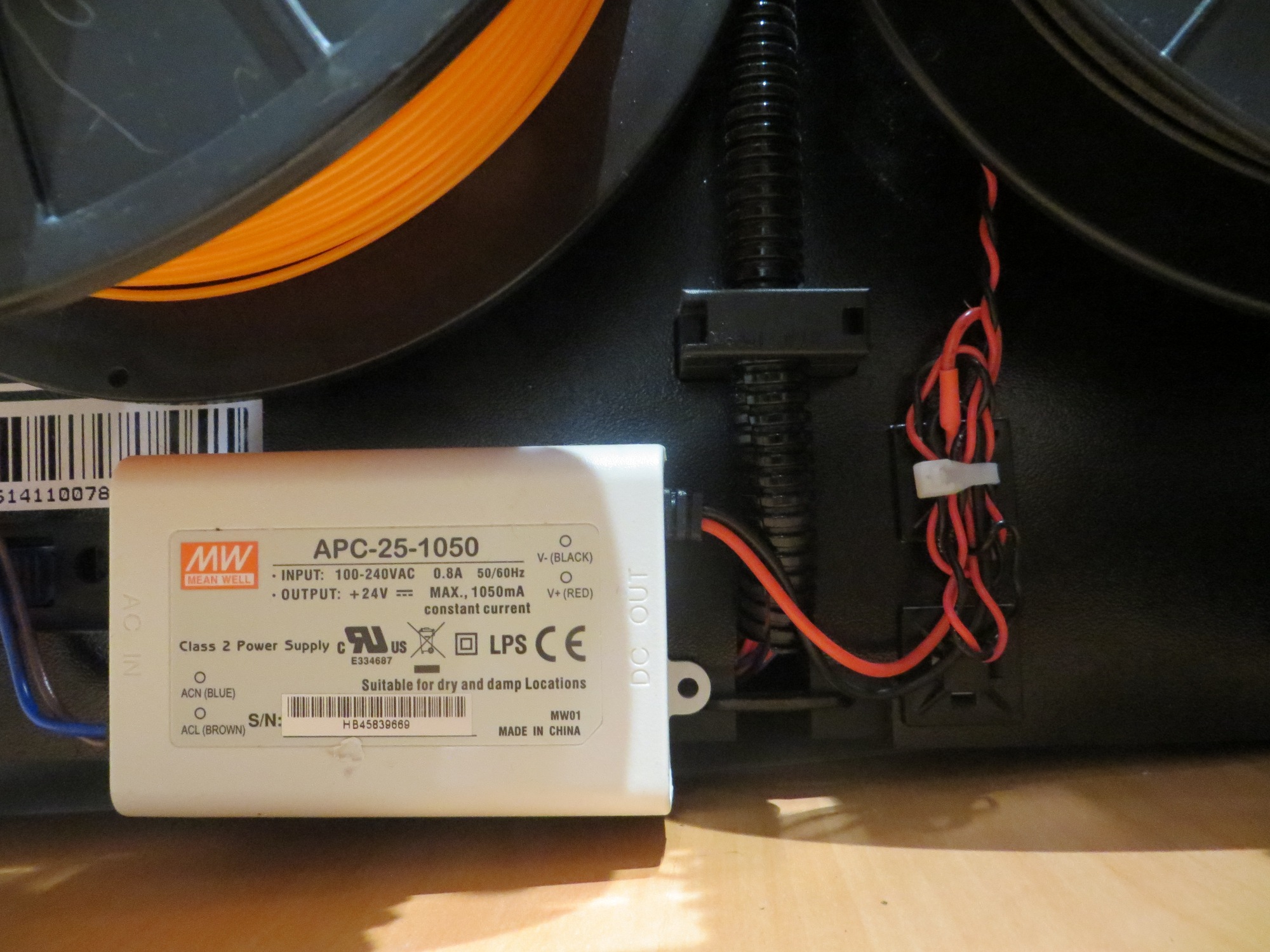
To power the lamps, I used a ‘Mean Well’ APC-25-1050 24VDC constant-current LED driver supply from ledsupply.com.  This is an incredibly cheap switch-mode power supply that delivers 1.05A constant current, with an output voltage from 12-24V.  This matched well with the 12-24V input spec for the LED auxiliary lamp, so I was in good shape.   I had a couple of these hanging around from a previous project where I  converted a crappy Lowe’s LED clip-lamp to a robust high-power LED lamp, so I got a two-fer (didn’t have to research/buy a power supply, and used up some of my excess stock – yay!).

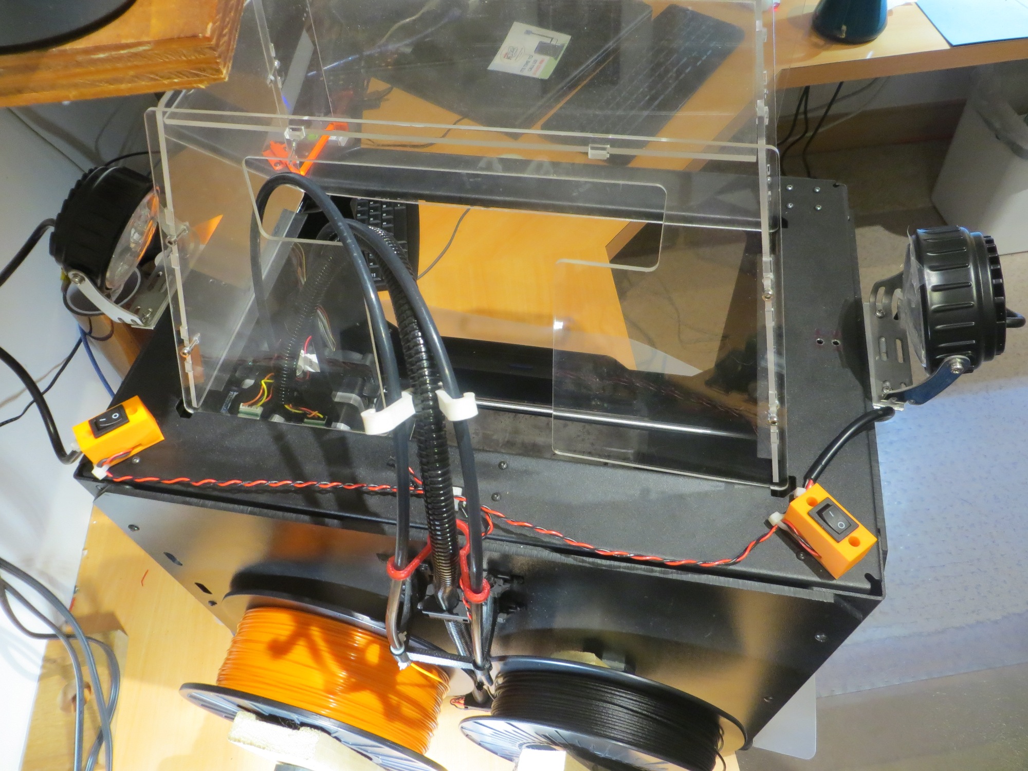
For  control, I decided to use individual power switches, mounted at the rear left & right of the cabinet.  I had some small SPDT power switches available, so I printed up a nice little housing with integrated  zip-tie anchor points for cable strain relief, and then ran a common power run down the back center of the cabinet to the power supply mounted on the back of the cabinet, below the right filament spool.

The following photos show the arrangement, and the build plate illumination during the first few layers of a test print.  Enjoy

Old vs New. Hanging bench lamp in foreground, new permanently mounted LED lamp in background

New LED lamps in action. Note the build plate illumination.

View from back of printer showing both LED lamps and ON/OFF switches

Mean Well APC-25-1050 1A constant-current LED power supply mounted at rear bottom of the cabinet

Build plate illumination with both LED lamps ON

Test print with both LED lamps ON

Test print with both LEDs OFF

View from top during test print, both LED lamps ON


Coffee pot filter holder handle repair with CFPETG

Posted 2 April 2017

No, this is not an April Fools prank – but an actual geek-type 3D printer project using 3DXTECH’s carbon fiber impregnated PETG filament.
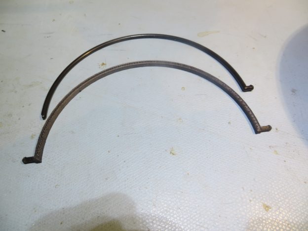
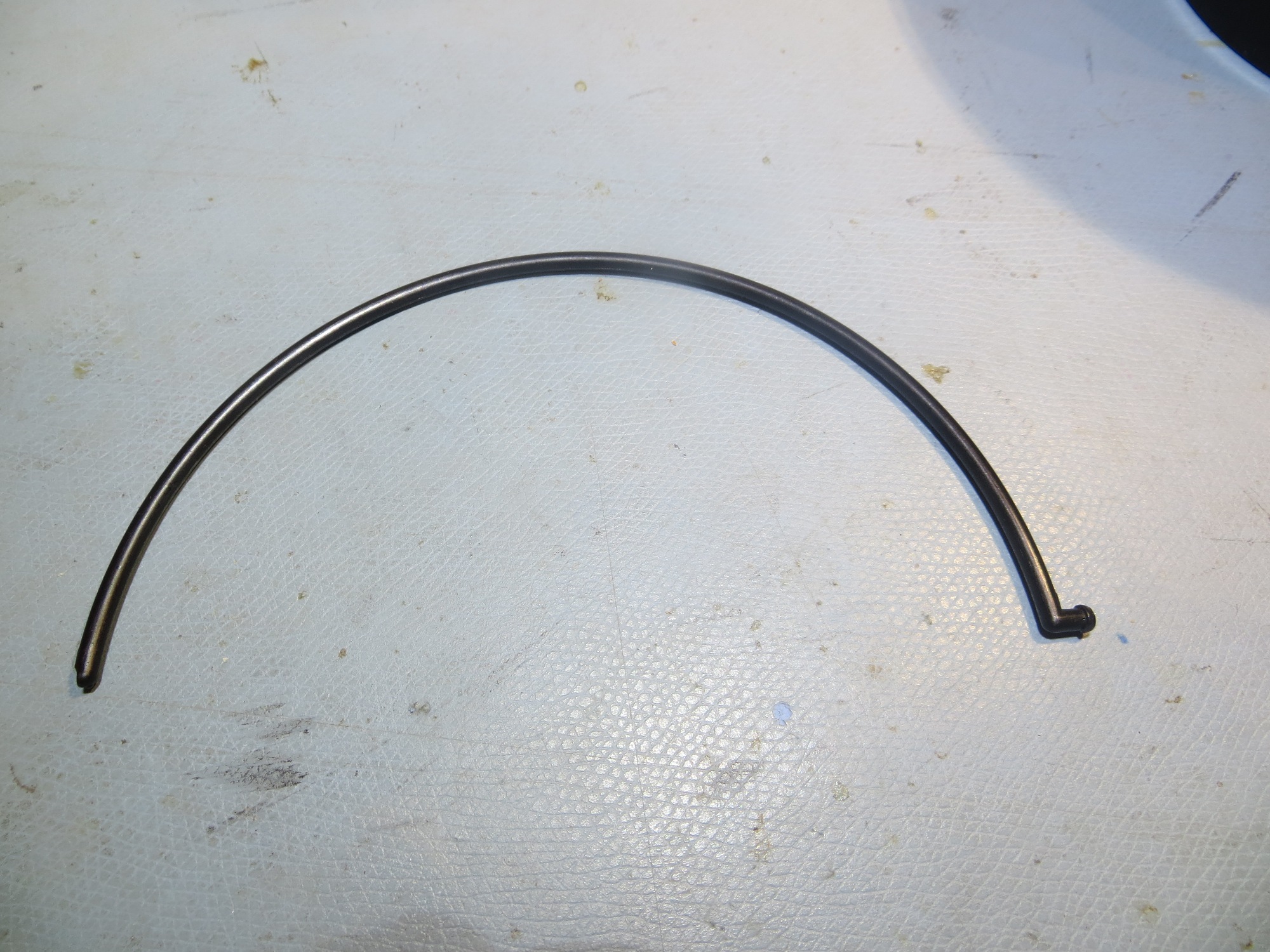
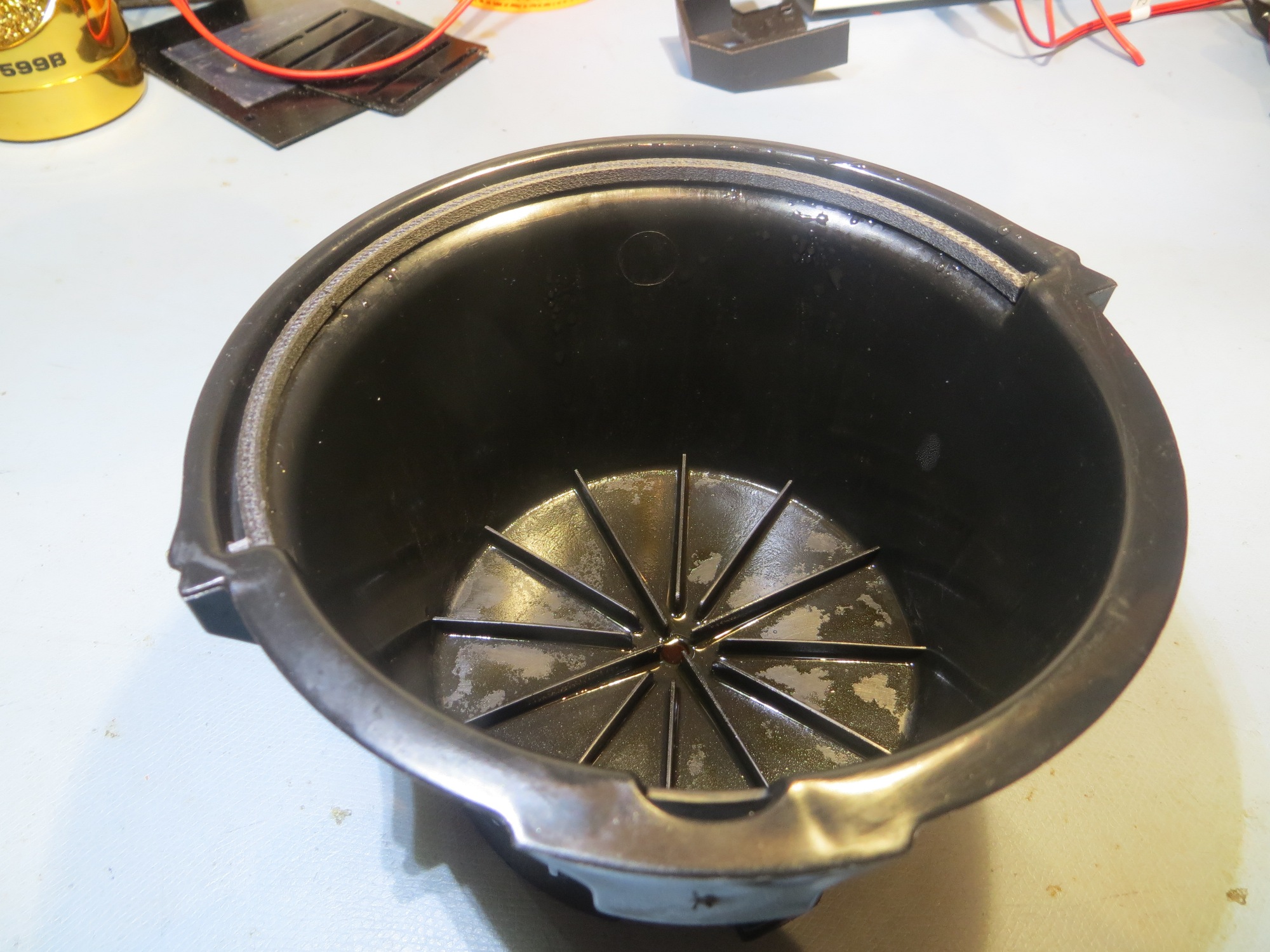
A day or so ago I was preparing my morning coffee as usual, when I discovered the little plastic ‘milk pail handle’ handle on the coffee filter holder had somehow gotten broken, as shown in the following photos

broken handle – note the missing tip on the left side

broken handle in action (or in this case, INaction)

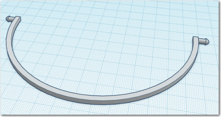
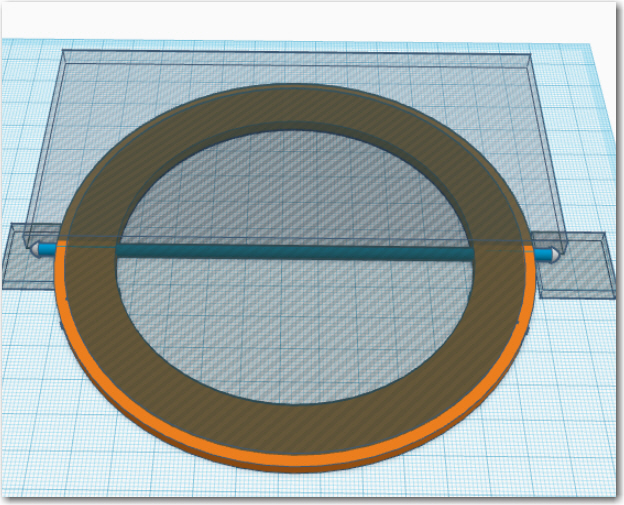
So, since I  hate defective products like this, and since I happened to have a 3D printer and some CF-PETG handy, I decided to see if I could 3D print a replacement.  Designing the replacement in TinkerCad turned out to be pretty straightforward, using a  rectangular cross-section for the handle rather than the original circular design.  The two retainer tips are cylinder sections (actually they are the ends of the same cylinder – with the middle removed along with the center of the disk making up the handle.  The TinkerCad design is shown in the following screenshots

Finished design

exploded view

After the usual 2-3 tries to get the printing parameters tuned up (seems they change slightly for every job), I got a very good print, as shown in the following photo

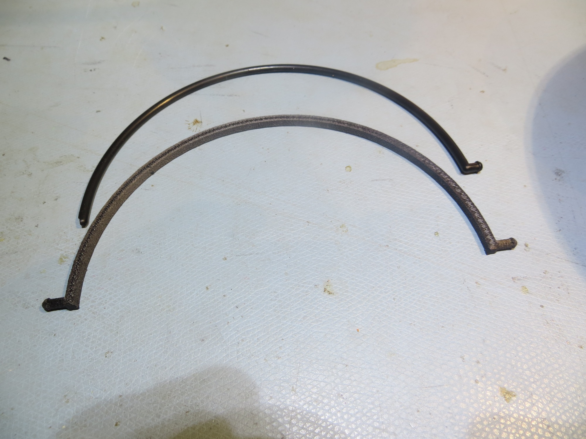
Broken handle and CF-PETG replacement. I only went through about 4 iterations over a few hours to get this right

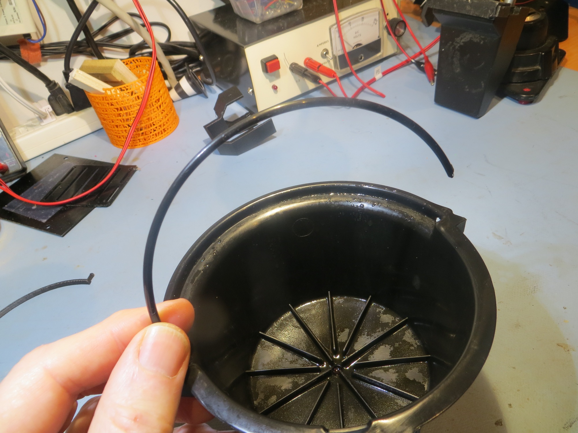
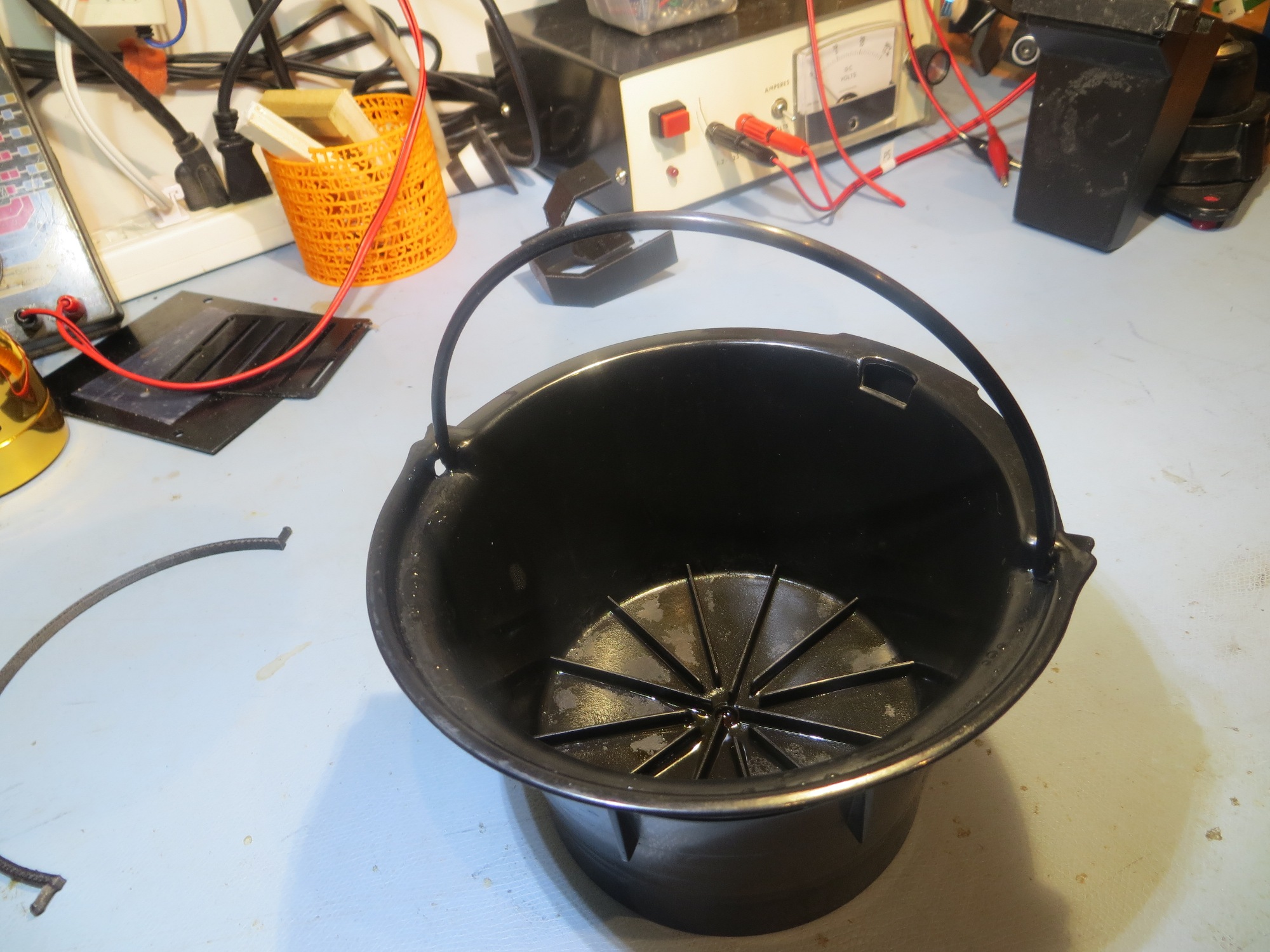
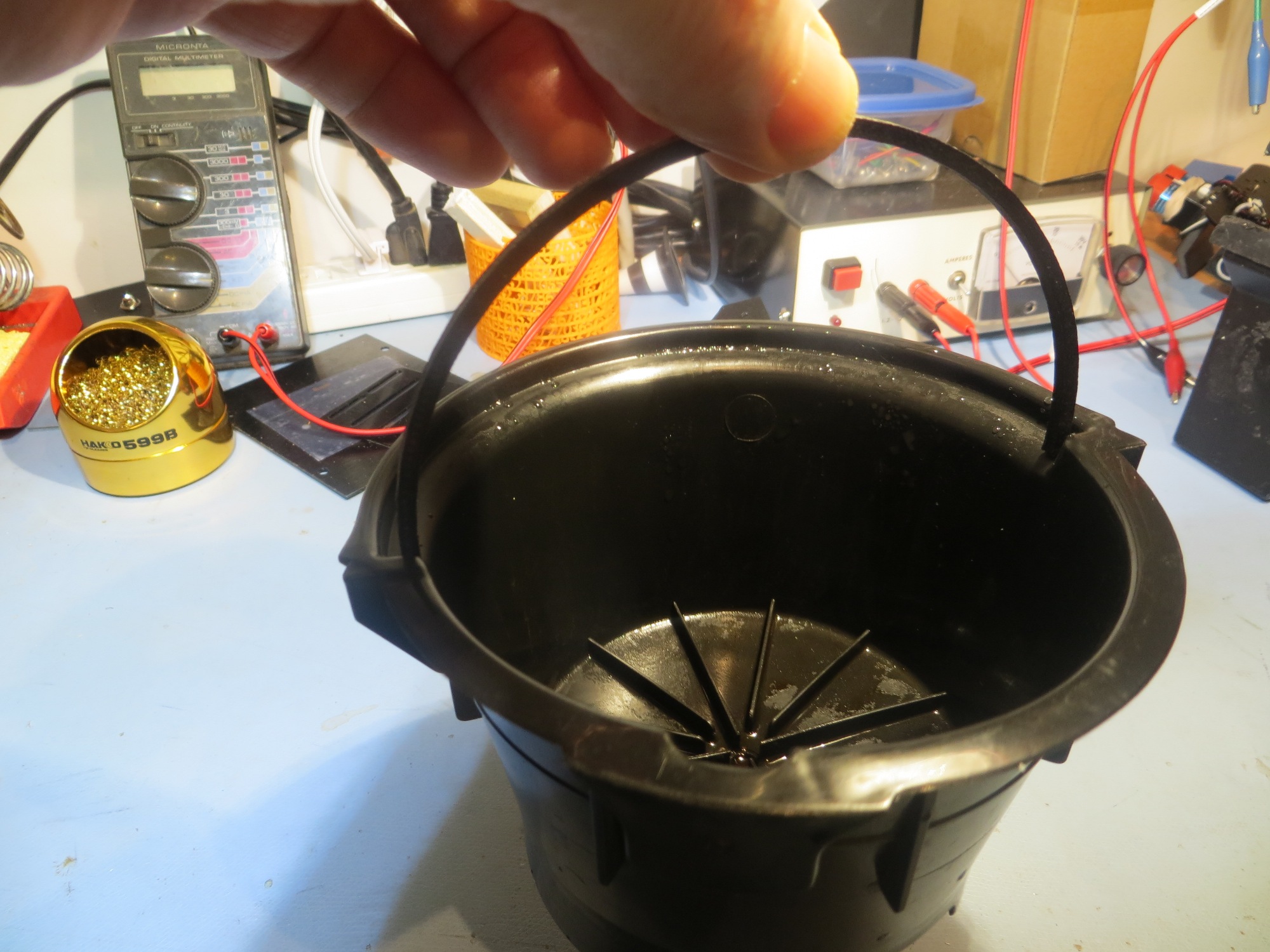
When installed on the coffee pot filter holder, it seemed to work very well – it allows me to pick up the holder by the ‘milk pail handle’ and it also stows away just like the original – yay!!

Replacement handle in action – lifting the filter holder as intended

Replacement handle in stowed position

B3DP (Before 3D Printers), it would basically have been impossible to repair this part.  Now, that’s not really a disaster, as it is perfectly feasible to use the holder forever without the little ‘milk pail handle’ but if you are a guy like me who  hates defective equipment, this would have been a burr under my saddle every time I used the coffee pot.  I  might have been able to find a replacement part somewhere, at some exorbitant cost (probably more than the entire coffee brewer) with a 6 week delivery lag time, but that would  just be a choice between two bad options; deal with a broken system every day, or just buy another brewer because of the failure of some 10-cent part 🙁

However, with my new 3D printer super power, the cost to repair is a few pennies of filament and a few hours of my time in my lab, which I love to do anyway – such a deal! 😉

Stay tuned!

Frank
 

Charging Station Design, Part XIII – More PID Tuning

Posted 28 March 2017

After my cleanup-and-label campaign documented in my last post, I was ready to get back to PID tuning for homing in on the charging station.  When my grandson was here, he pretty much took over my primary work area, so I was forced to move my bench-top testing range to another part of my bench.  This was not quite as convenient for reprogramming the bot, but it did give me a bit more distance between the initial bot position and the IR LED in the charging station, as shown in the following photo

Wall-E2’s new PID test range

I started out by going back to the simplest possible PID setup – namely (p,i,d) = (1,0,0) and ran a series of range tests, as shown in the following video.

As is evident in the video, Wall-E2 has no difficulty homing into the charging station when initially placed near the edge of the bench, but won’t home properly from the other side.  After thinking about this for a bit, I came to the conclusion that the reason for this is that the center of the charging station is physically located near the edge of the bench, so when the bot starts at that edge, it is actually close to the centerline of the charging station, and therefore is almost perfectly lined up at the start. When starting from the other side however, the initial position is not lined up with the charging station centerline and therefore has to make more of a correction to get lined up.  From this I hypothesized that the PID setting of (1,0,0) doesn’t provide enough of a wheel-speed correction to make the required turn.

So, next I tried a PID of (2,0,0), and this worked much better, as shown in the following video

As can be seen from the first run above, the robot is doing a much better job of homing, but unfortunately ran into the left side rail instead of being captured.  This turns out not to be a PID tuning issue, but rather a problem with the IR beacon pattern relative to the lead-in rail arrangement.  The line from the robot’s starting position to the IR LED unfortunately intersected the outside of left lead-in rail instead of the inside.

As an experiment to confirm the IR beam pattern hypothesis, I printed up an auxiliary part to restrict (not collimate, as that implies shaping) the beam to a narrower pattern, as shown in the following photos  ( taken with a digital camera with a wavelength range that covers the  IR wavelength being used)

This experiment ‘worked’ in the sense that it showed that the IR beam was no longer visible outside the lead-in rail aperture, but it also made it so narrow that the robot had to be right on the centerline to sense the IR beam at all.  Although this solves the problem of hitting the rail, it would make it very difficult for the robot to ever find the charging station in the first place when approaching at the typical wall-following standoff distance.

So, although I plan to do a bit more fine-tuning of the PID parameters, it appears that the basic homing problem is solved,  but the challenge now is  getting the robot into a position where it can home in on the IR beam without running into a side rail.  The current wall-following algorithm doesn’t have a set stand-off distance, so the robot may be ‘cruising’ at anywhere from 10-70 cm from the wall being tracked.  Assuming that one lead-in rail is against the wall, the IR led is located about 20 cm out, and the front end of the outside lead-in rail is about 35 cm out.  When the robot is just captured by the outside rail, its centerline is about 16 cm out.  The angle from the IR LED to the center of the robot at this point is about 11-12 º.  So, assuming the robot is wall-following and at some point intersects the IR beam and starts homing, the angle from the robot to the IR LED has to be less than 11-12 º or the robot will not be captured by the lead-in rails.  The situation is shown graphically in the following diagram.

Capture parameters for the robot approaching a charging station

As shown above, if the robot is ‘cruising’ at 45 cm from the wall, then it has to start homing from no less than 1.7 m or so from the charging station in order to get captured by the lead-in rails.  This is  a large, but impossible distance.  The robot can currently home from about 1 m out, so getting out to 1.7 m might be as easy as increasing the IR LED current;   it is  currently running at about 30 mA, and it is rated for 100.

Another possibility is to angle the capture gate out slightly with respect to the wall. There’s no real reason the charging station rails need to be parallel to the wall – it’s just my neat-freak mentality that makes me do things that way.  If I angle it such that the inside lead-in rail touches the wall at both its forward and trailing ends, that will angle the beam out at about 13 º, and move the minimum capture distance in to about 1.0 m, as shown in the following diagram.  1.0 m is just about where the robot is capturing now – yay!!

Tilted gate option. The tilt decreases the minimum required IR beam capture distance from about 1.7m to about 1.0m

So, it appears that tilting the capture gate is the way to go; this doesn’t cost anything but a slight ding in my ‘neat-freak’ index, and should  eliminate or greatly reduce problems with charging station capture failures.

Stay tuned,

Frank
 

Charging Station Design, Part XII – A Pause to Clean Up

Posted 22 March 2017

This last weekend was devoted to a whirlwind visit by the St. Louis family, which includes my 13-year old, growing-like-a-weed, 3D printing enthusiast grandson.  So, I didn’t get a whole lot of time to work on Wall-E2’s problems, as Danny basically took over my entire lab ;-).  So, now that the horde (can one 13 year-old kid constitute a ‘horde’?) has departed, I can get back to some sort of normalcy and make some progress.
At the end of my last post on this subject, I had concluded that I needed to go back and verify the details of the IR homing hardware and software, as the results I was getting didn’t make sense.  So, I set up some experiments where I could carefully watch the raw output from all 4 IR detectors, and the changes from physically blocking one IR LED at a time.  This experiment convinced me that something was definitely wrong with the hardware; at least one detector appeared to be dead, and it also looked like blocking one detector affected the outputs of more than one – strange!

So, back to the hardware; After dismounting the combined charge status display panel/IR detector module and separating the two, and physically inspecting the IR detector module I  found  a bad solder joint (what – a bad solder joint!?  I  never make bad solder joints! – must have been someone else!) on one of the detector connections to the interface  header.

After repairing the bad solder joint, I carefully worked my way through the cabling maze on Wall-E2 to the microcontroller end of the IR detector cable, to verify proper connection on that end.  The connections looked good, so I did some more testing, only to find that one of the IR detector outputs appeared to be dead – it’s analog reading stayed around 4-500 no matter what I did.  Some more physical inspection revealed the problem – my 4-pin IR detector cable was connected to A2-A6 on the Mega board, but I was reading A1-A5, so the A1 input was essentially ‘open-circuit’ – oops!

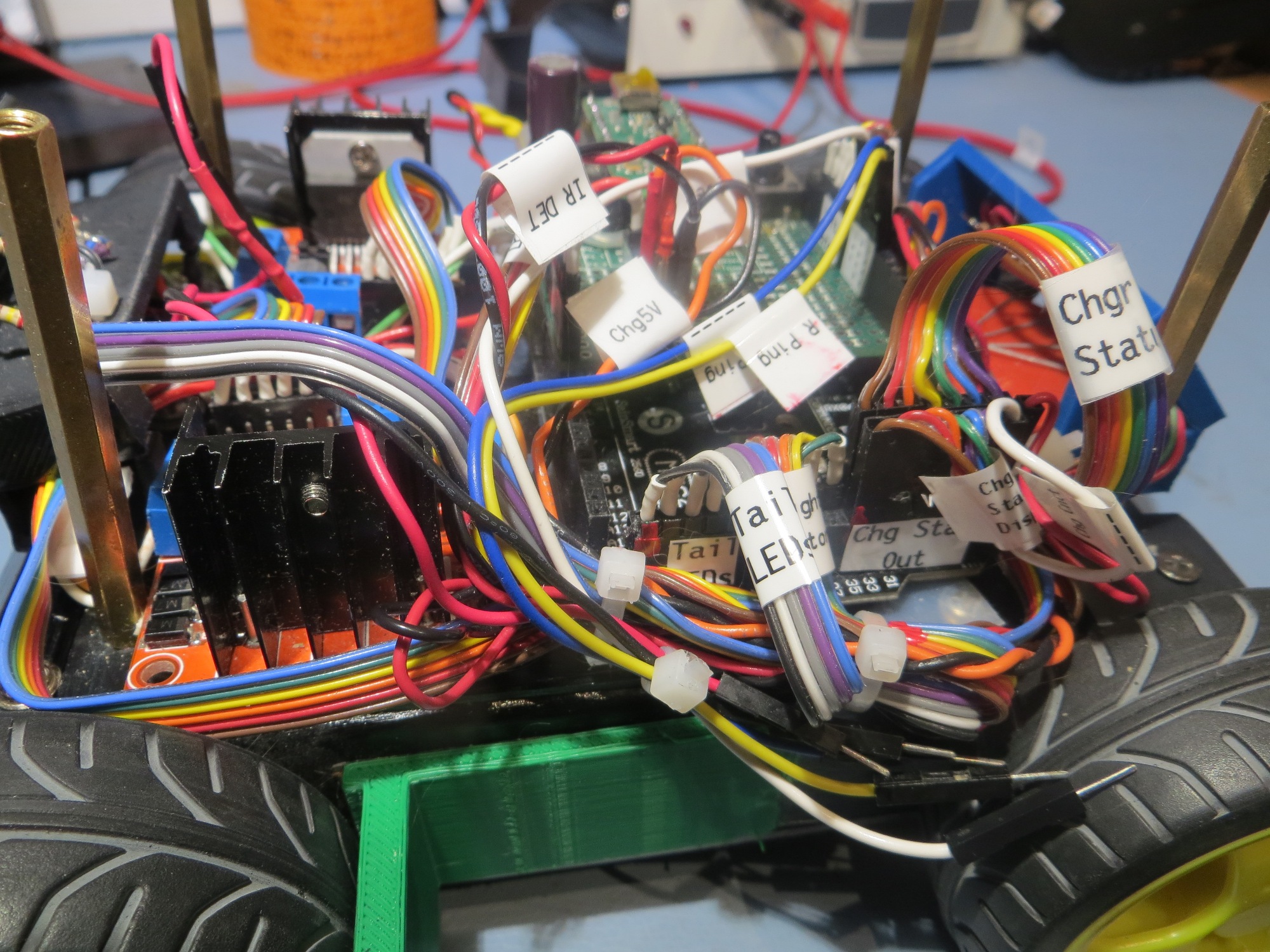
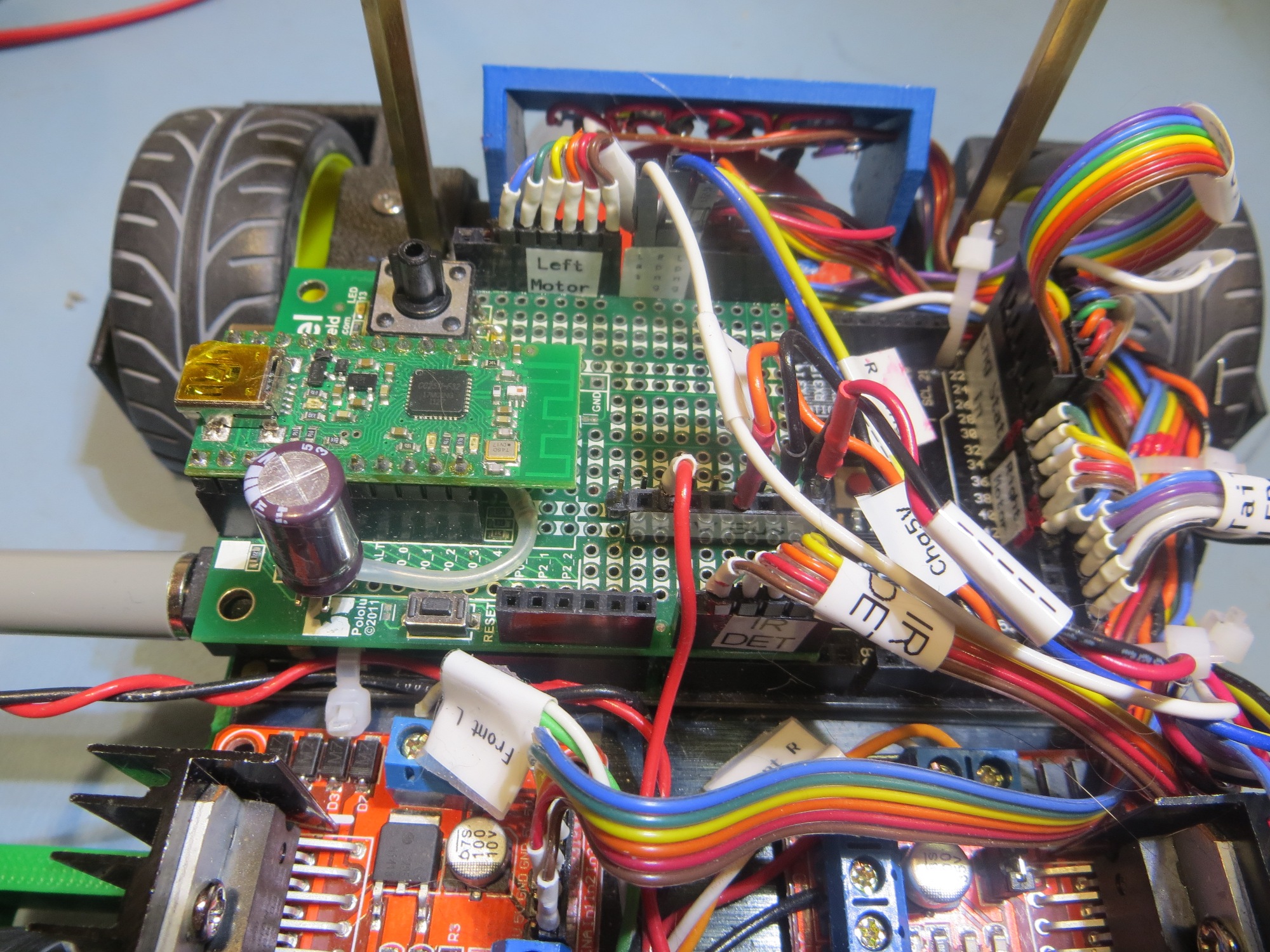
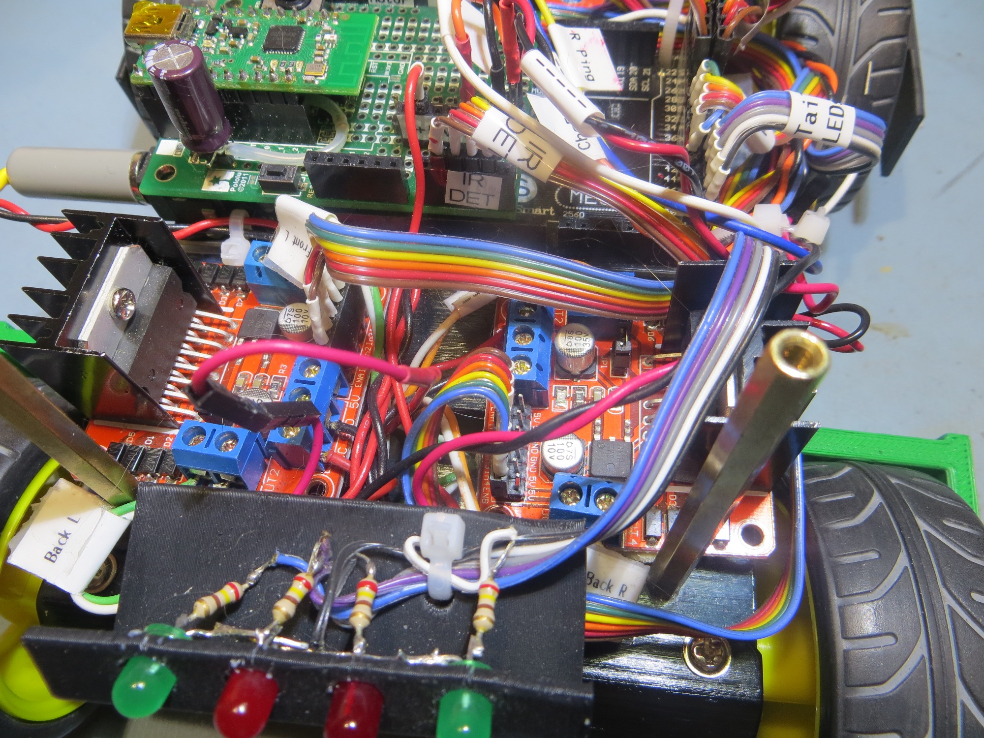
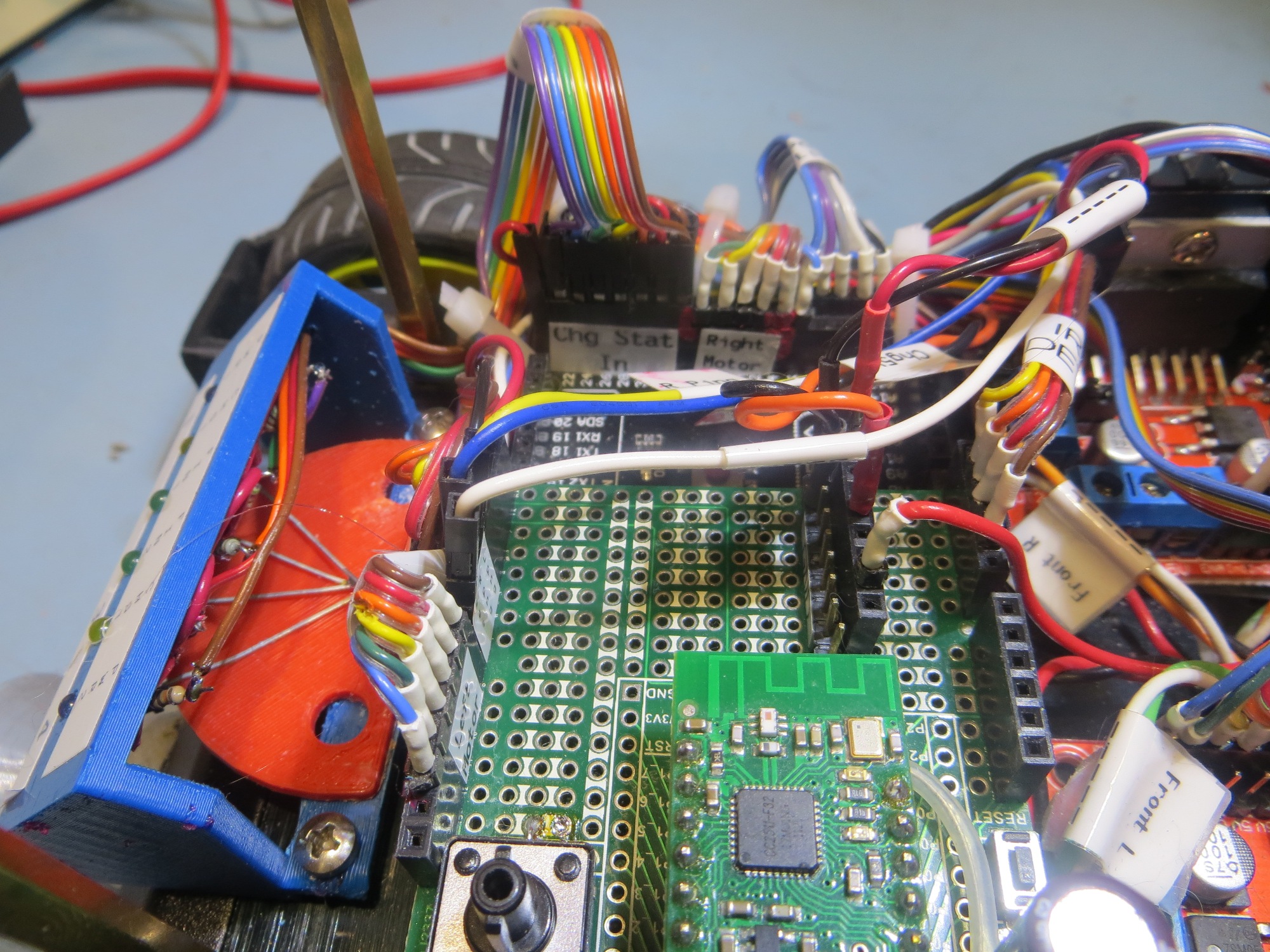
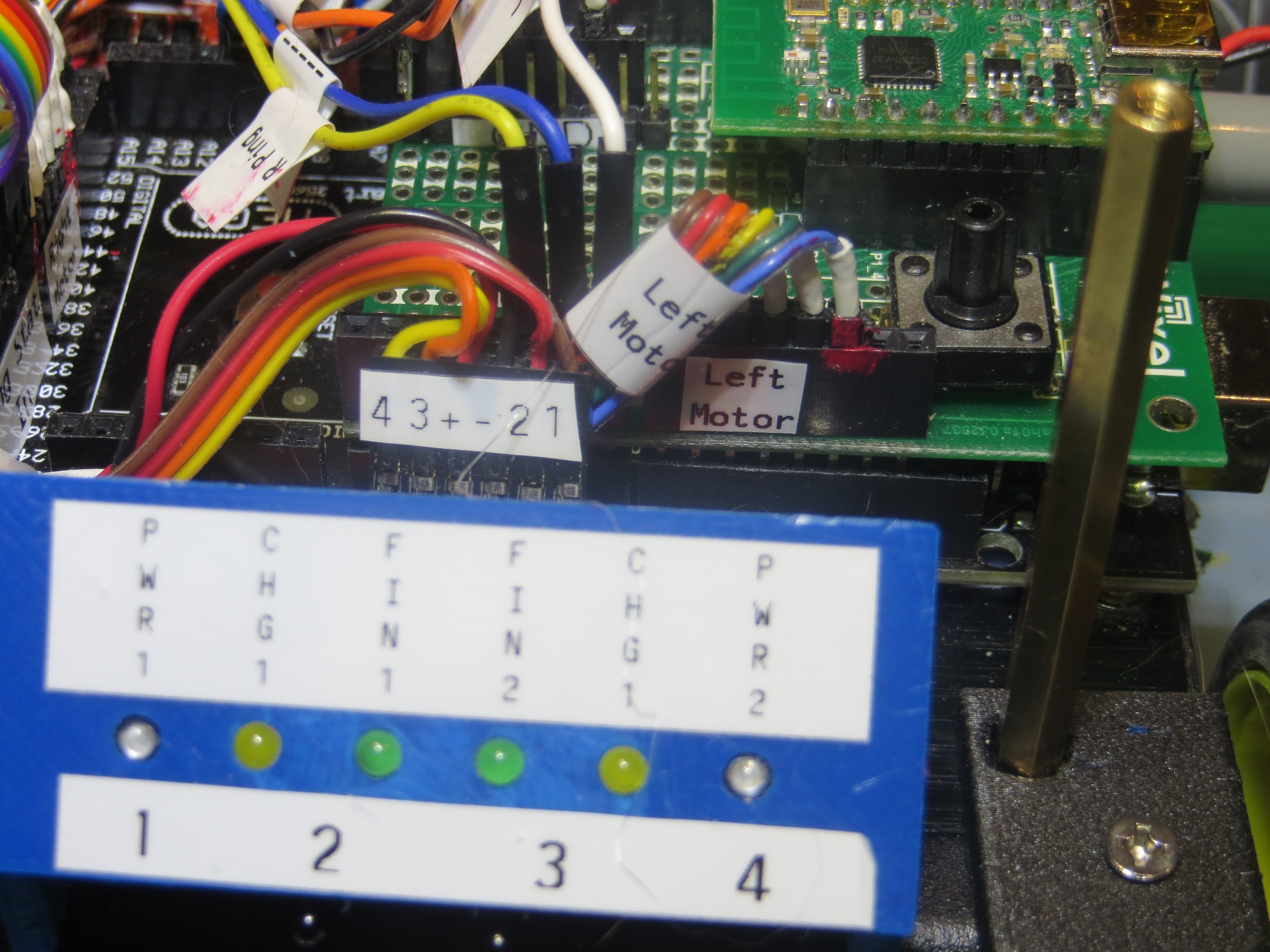
After fixing this booboo, things started to perk up and act a *lot* more normally! ;-).  However, instead of immediately going back to testing mode, I decided that I needed to get serious about labeling and indexing cables (I use red fingernail polish to index one end of each connector to the corresponding microcontroller pin) and connectors  on Wall-E2, so I would have less trouble in the future with the large number of ribbon cables and loose wires now festooning the robot.   Fortunately I have my wonderful Brother P-touch label maker to help me with this task. As an aside, if you are a ‘maker’ hobbyist like myself, a label maker is an absolute godsend, and I can’t recommend the Brother P-touch highly enough.

After my labeling and cleanup campaign, Wall-E2 is  a lot more self-documenting, as shown in the following photos

Printing with 3DXTech Carbon-Fiber PETG – Solved!

A couple of months ago, I got some 3DXTech carbon fiber PETG filament to play with, and I have been having mixed success printing with it on my PowerSpec 3D PRO (FlashForge Creator PRO clone) dual-extruder machine.  My first few prints were pretty nice, but lately I’ve been having problems.  The prints turn out messy and stringy, with almost no strength – as if the layers aren’t fusing at all. I can easily snap pieces apart, where before they were quite robust.

In an effort to troubleshoot the problem, I have done the following:

  • Replaced both nozzles with 3DxTech hardened steel models
  • Re-leveled the build plate
  • Gone through the excellent XYZFABS PETG printing tips here.
  • Set the z-axis offset to 0.02mm in S3D gcode
  • Set the filament feed multiplier to 0.88 as recommended
  • Set the extruder temp to 220, bed temp to 100

With the above settings, I tried a 20mm cal cube, but it  started ‘air-printing’ after about 15mm from the base (filament under feeding?).

  • Set the filament feed multiplier to 1.20 and tried again.  This time I got a nicer print, but it still failed at 15mm with a feed jam and obvious gear tooth wear on the filament – clearly over-feeding.
  • Set feed multiplier back to 1.10 and tried again.  This time it started ‘air-printing’ at about 4mm up.
  • Changed extruder temp to 230 and tried again.  This time it failed to adhere 1st layer to print bed.  This caused a ‘blob’ on the extruder tip, which resulted in sidewalls that were over-printed and ragged.
  • Changed print multiplier to 1.00 and tried again.  This time the print didn’t adhere to the print bed at all
  • Changed z-axis offset back to 0.00.  This resulted in an almost perfect print.  Sidewalls were very nice, and although there was some ‘globbing’ during bridging on the top, the final top layer was almost perfect.

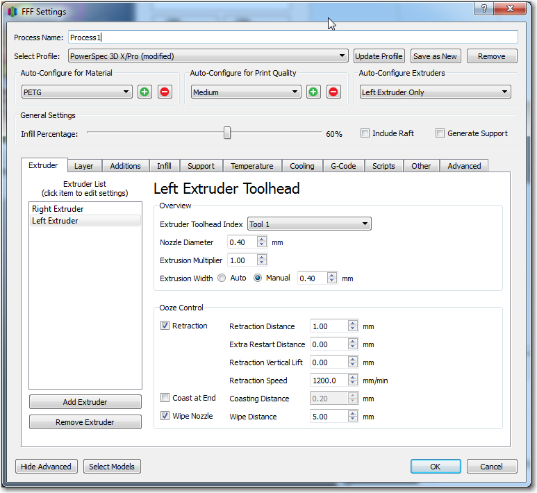
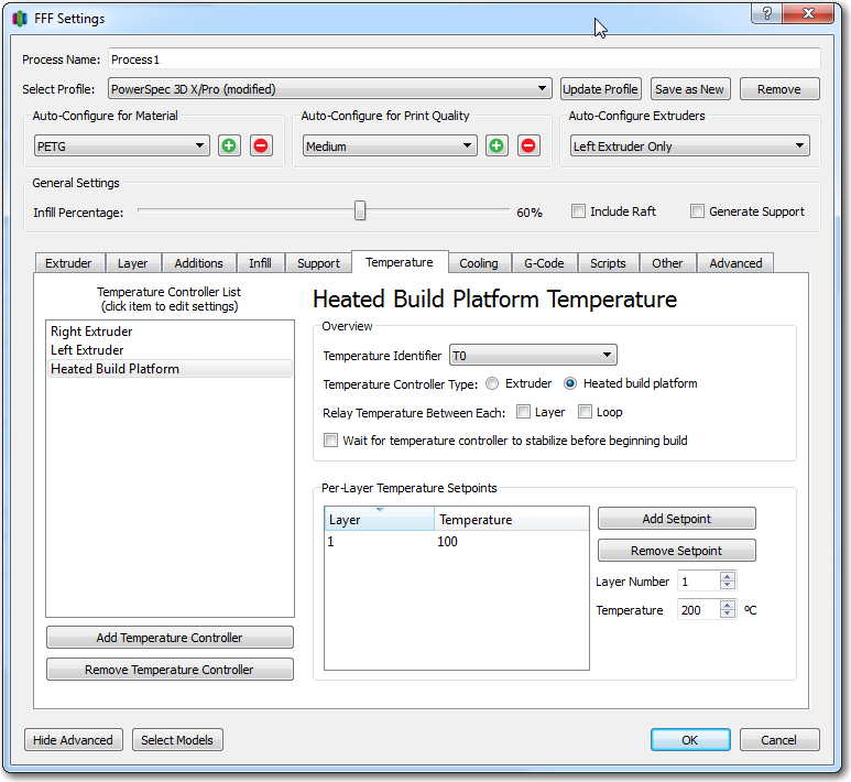
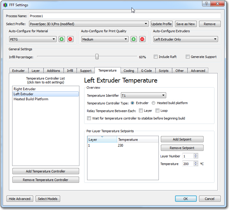
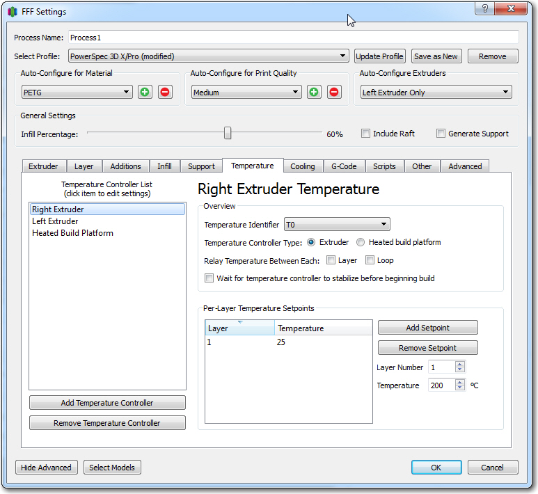
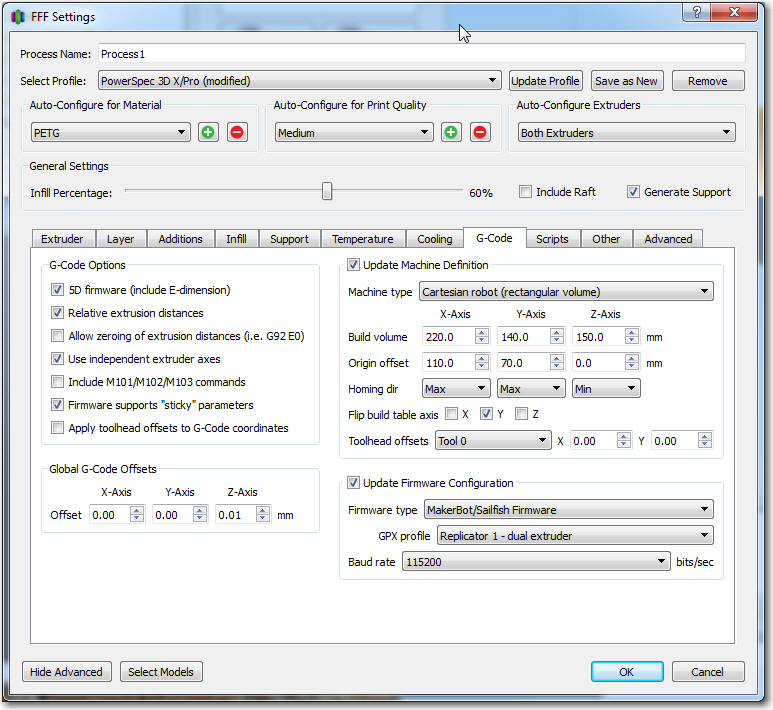
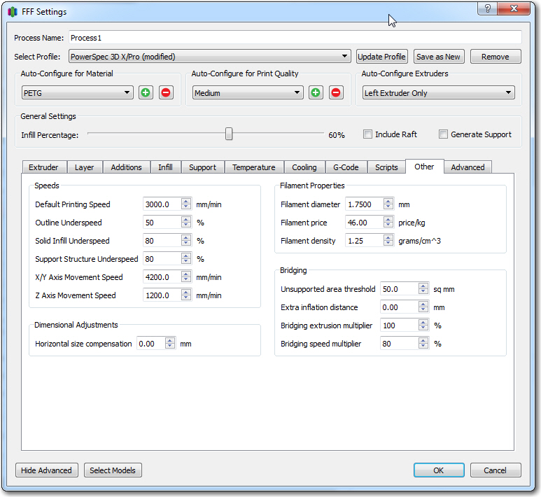
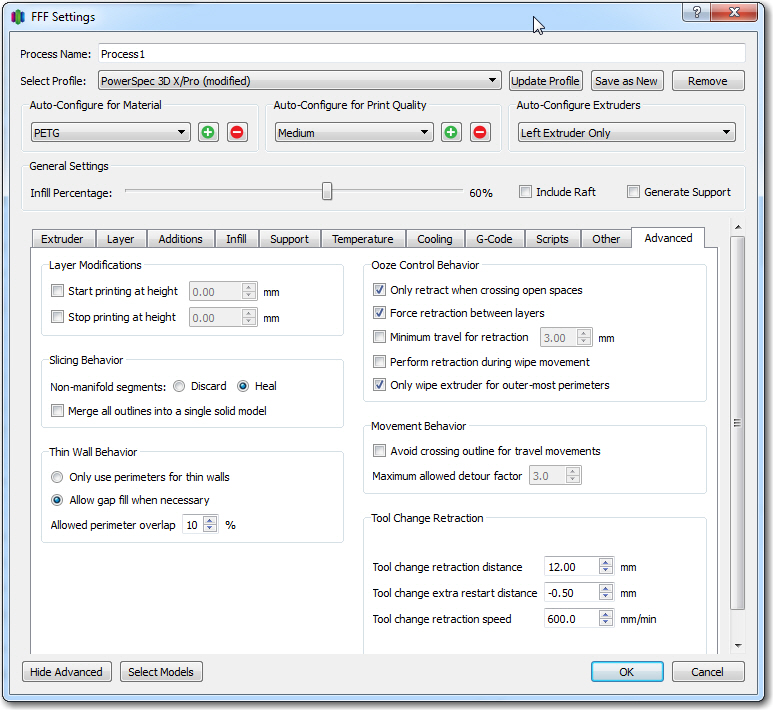
So, the final settings for a good print are:  Feed multiplier = 1.00, Bed temp = 100, extruder temp 230, z-axis offset 0.00, unused extruder temp set to 25 (can’t set to 0, as this gets overwritten by printer), as shown below in the S3D process settings screenshots

23 March Update:

Last night I printed a second 20mm cal cube using the same settings as above, and this time the bottom layers did not print correctly (sides and top did OK).  So I tried again this morning, with the following change:

  • Changed z-axis offset from 0.00 to +0.01mm, and changed the unused extruder temp from 25 to 75 (this last settings change is an attempt to fool the printer into showing percentage completion as normal. With an unused extruder setting of 25, the top line of the display shows ‘heating’ continuously)

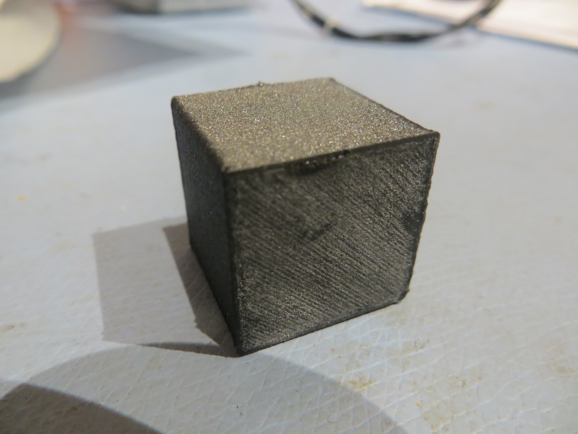
With the above changes, I got an essentially perfect cal cube print, *and* the top line of the display showed percentage completion instead of just ‘heating’ (the right extruder temp display showed 75/75, so that pretty much confirms my theory about the printer having to match actual and requested temps in order to progress to the ‘percentage completion’ display mode)

Essentially perfect 20mm cal cube print with 3DXTech Carbon Fiber PETG filament

Unfortunately, when I tried to print the TinkerCad model shown below (it’s the front right wheel bumper for my robot), I could not get a decent print no matter what I did.  Either the first layer wouldn’t adhere, or the filament feed failed partway through the print, or the finished print was way to fragile for use.  I finally had to give up on the 3DXTech filament entirely and print the bumper using ABS (which printed perfectly the first time!).  This was very disappointing to me, as I had previously successfully printed two of these wheelguards using the 3DXTech filament – so I’m not sure what changed to make it difficult/impossible to do it now 🙁

Right wheel guard for Wall-E2 (blue material is support). Printed perfectly the first time with ABS, but not with 3DXTech Carbon Fiber

ABS with ABS support printed perfectly on the first try

Frank

25 March Update:

Yesterday I did what I should have done when I first started having problems with the filament, namely shooting off an email to 3DXTECH.  I quickly got a response back from Matt Howlett, the  company’s founder, with a what looks like their stock reply for people having problems.  Most of the stuff in the list I had already covered, but there were a couple I hadn’t tried, and one of them was raising the extruder temp from 230 to 240-245.

So, I reloaded the carbon fiber PETG on my printer, and printed a 20 mm cal cube with Matt’s recommended settings, except for a bed temp of 90 vs 65 (because I have a PEI bed and don’t want to use hairspray, and print speed of 3000mm/min vs 4000.  This time the cal cube printed perfectly, and I could not damage the finished cube with finger pressure like I could before.

Next, I tried a full print of my right wheel guard model for Wall-E2.  To simplify things, I used the carbon fiber PETG filament for both the model and the support material (I was having trouble before getting the support material to stick at the bed temperature I was using for the carbon fiber PETG material), and lo-and-behold, this print also turned out perfectly, as shown in the following shots.

Just starting the print

About 1/4 the way through, printing nicely

About 2/3 of the way. Note how well both the model and the support area adhered to the bed

Finished print!

Finished product – and quite strong.

When I made this one change, all of a sudden I was getting almost perfect prints!  Now I feel like an idiot for going through all this wailing and gnashing of teeth when all I needed to do was raise the extruder temp 10 deg!  Now I have been forced to ‘eat my hat’ (and my complaints to 3DXTECH!) – OOPS!!  However, since I am now back to being able to make strong carbon fiber prints, I’m more than willing to accept the trade-off! ;-))))

Stay tuned,

Frank


Charging Station Design, Part XI – PID Tuning

Posted 14 March 2017

As I was doing the IR homing tests described in my last post, I noted that Wall-E2 wasn’t all that great at homing; in particular it missed the opening in the lead-in rails on several occasions, instead hanging up on one side or another.  This was a bit mystifying to me, as I thought I had the homing code working very well with my old 3-wheel robot (see ‘IR Light Follower for Wall-E2, Part X – More PID Tuning‘).  At the time, I decided to use one of my best scientific research tools and simply ignore the problem, hoping it would either go away, or my subconscious mind (by far smarter than my conscious one!) would figure it out in the shower or while drifting off to sleep.

And, in fact, last night while drifting off to sleep, I remembered that the PID tuning for the 3-wheel robot had to take into account the fact that  even small  differences in drive wheel speeds get magnified by the free-castering front wheel.  Wall-E2, with its all-wheel drive  behaves entirely differently, and since small wheel speed differences don’t get amplified into big directional changes, the PID tuning parameters appropriate for the 3-wheel version are too passive for the 4-wheel one.

So, I went back to the drawing board (again!) for PID tuning for the 4WD Wall-E2, starting with the current 3-wheel parameters as the ‘too passive’ baseline.  From my previous article, the final PID parameters were P = 0.1, I = 10, D = 0.2, with the input scaled by 1, 5, or 10 depending on IR beam signal strength.  My initial thought is that the 4WD robot needs a lot more ‘D’ (differential) to increase its turn rate with respect to IR beam heading changes, so I tried a couple of runs with the D value increased from 0.2 to 2 (factor of 10 increase).  As the following video shows, this did seems to increase Wall-E2’s agility somewhat, but still not enough to overcome even minor initial heading offsets, especially to the left.

After some more testing with different values of P,I,D, I began to wonder if I might be having problems with the basic IR detection hardware and homing software, independent of the PID tuning issue.  When I did the previous PID study, I also captured the raw detector data, which allowed me to determine how the PID tuning and the basic detection hardware/software were interacting.  I may have to go back and do that again with the 4WD setup

Stay tuned,

Frank