Posted 06 August 2017
Now that I have the 2-channel IR demod algorithm working, it’s time to start integrating the capability back into my long-neglected Wall-E2 robot. The grand plan here is to incorporate the IR demod algorithm into a ‘IR Homing Module’ with raw IR sensor input on one end, and (R-L)/(R+L) normalized steering information output on the other, as shown in the following diagram.
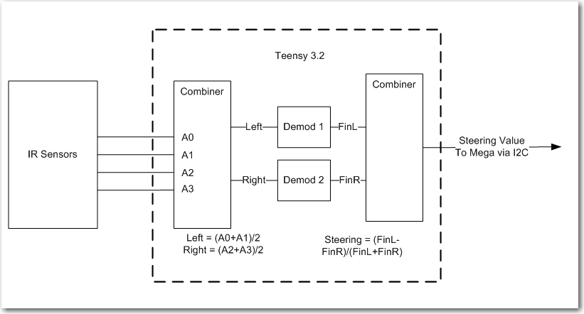
Teensy 3.2-based IR Demod module block diagram
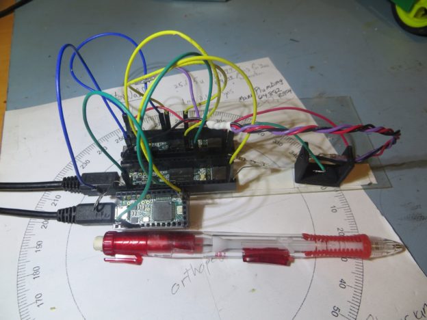
As the first step in this project, I wanted to verify that I can port the IR demod algorithm from its current Teensy 3.5 SBC host to a Teensy 3.2. The Teensy 3.2 is about half the size of the 3.5, runs at 72MHz instead of 120MHz, and has “only” 64KB RAM instead of the 3.5’s 192KB. I didn’t think any of this would matter, but you never know ;-). The code modifications required to run this test were pretty trivial; I had to comment out the DAC1 setup lines, and change the pin number for the Channel 1 DAC0 output from A21 to A14. Then I commented out the lines that transmitted the Ch2 final value to the now-nonexistent DAC1 port and that was it. The following photo shows the T3.2 in the foreground, with the T3.5 sweep generator next back, and the original T3.5-based IR demod host in the background
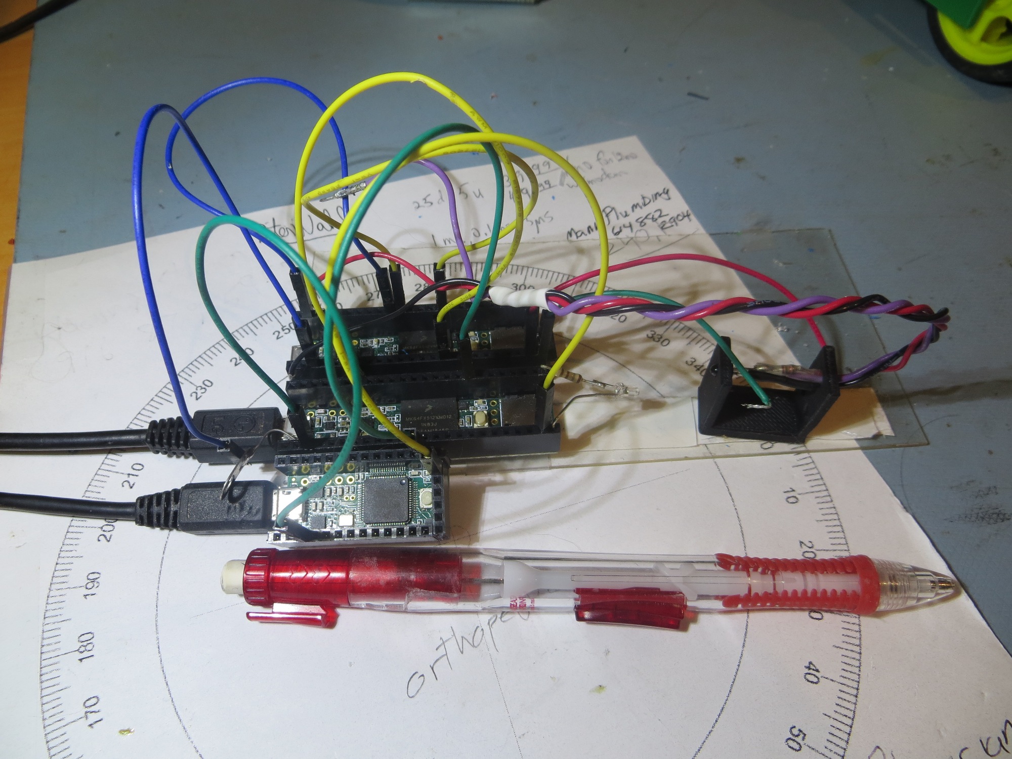
Teensy 3.2 trial as host for IR demod algorithm. The Teensy 3.5 in the middle is the sweep generator and the one in the back is the original host for the 2-channel IR demod algorithm
After making the above changes, I ran a frequency sweep from 510 to 530Hz in 0.1Hz steps, 0.5S/step, with the following results.
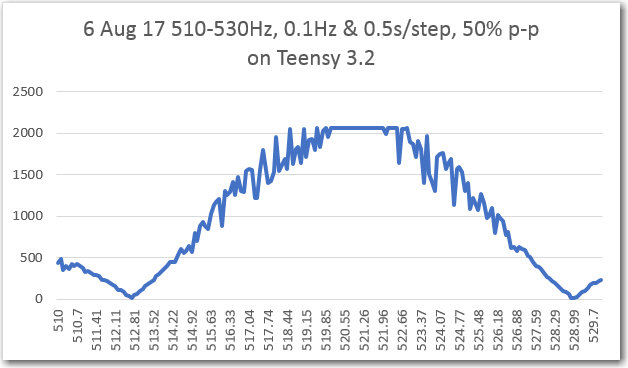
Frequency sweep of the IR demod algorithm hosted on a Teensy 3.2
For comparison, here is the same plot from the previous post using the Teensy 3.5.
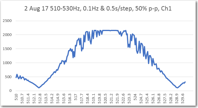
I think it’s safe to say that the Teensy 3.2 operating at 72Mhz is doing as good a job with this algorithm as the Teensy 3.5.
So, the next step was to figure out how to get the steering information from the Teensy to the main robot controller (a Mega 2560). I decided to use the I2C port for this purpose; the Mega has one I2C port, and the Teensy has several, so this should work. Of course that means I have to figure out how to actually use the I2C capability, but hey – that’s what the internet is for ;-).
In any case, I found the new i2c_t3 library for use with Teensy 3.x, and the ‘I2C_Anything’ library for transparently handling arbitrary data types, and a couple of examples showing their use. With these (and my handy-dandy Teensy testbed) I was able to implement a little master/slave demo project to confirm that I could use I2C to transmit float data values from the Teensy 3.2 I would be using as the IR homing beacon demodulator to the Mega.
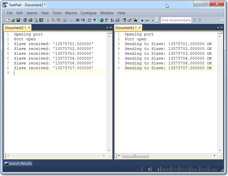
Output from master/slave demo project
So the next step is to integrate the above master/slave I2C code into the Mega 2560 and the Teensy 3.2. The plan is to have the Mega request data from the Teensy, and the Teensy will then transmit the latest L/R steering value. There will be no buffering on either end, so whatever the Mega doesn’t request will simply fall off the end into the ‘bit bucket’.
Currently, the IR phototransistors appear on pins 55-58 (A1-A4) on the Mega. These will be transplanted to pins 14-17 on the T3.2 (A0-A3). GND will go to GND, and +5V from the Mega will go to ‘VIN’ (+5V with USB connected) on the T3.2. With this setup, and a few modifications to the ‘Master’ sketch in my previous master/slave demo program, I should be able to transmit a 520Hz square-wave modulated IR signal to the IR detectors, and have it appear on the master’s serial port after having been demodulated by the T3.2 – stay tuned! 😉
As an interim step, I disconnected the four IR sensor leads from the Mega 2560 and reconnected them to the T3.2, as shown below.
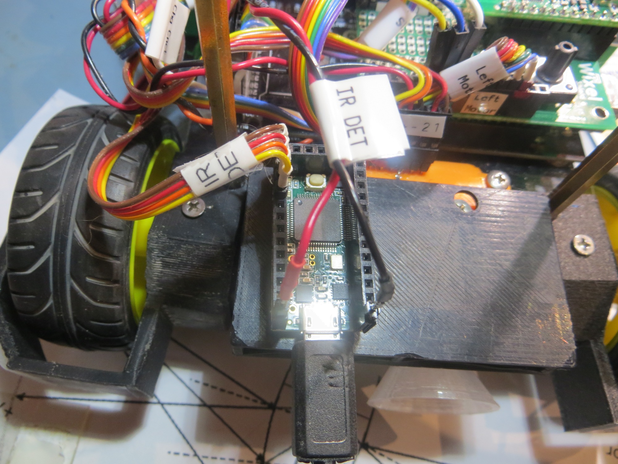
IR sensor connections moved to the Teensy 3.2 IR Homing Module
Next I set up an IR LED source a few inches away from the detector array and moved it from right to left across the array field of view, and recorded the raw sensor data as received by the Teensy, as shown below:
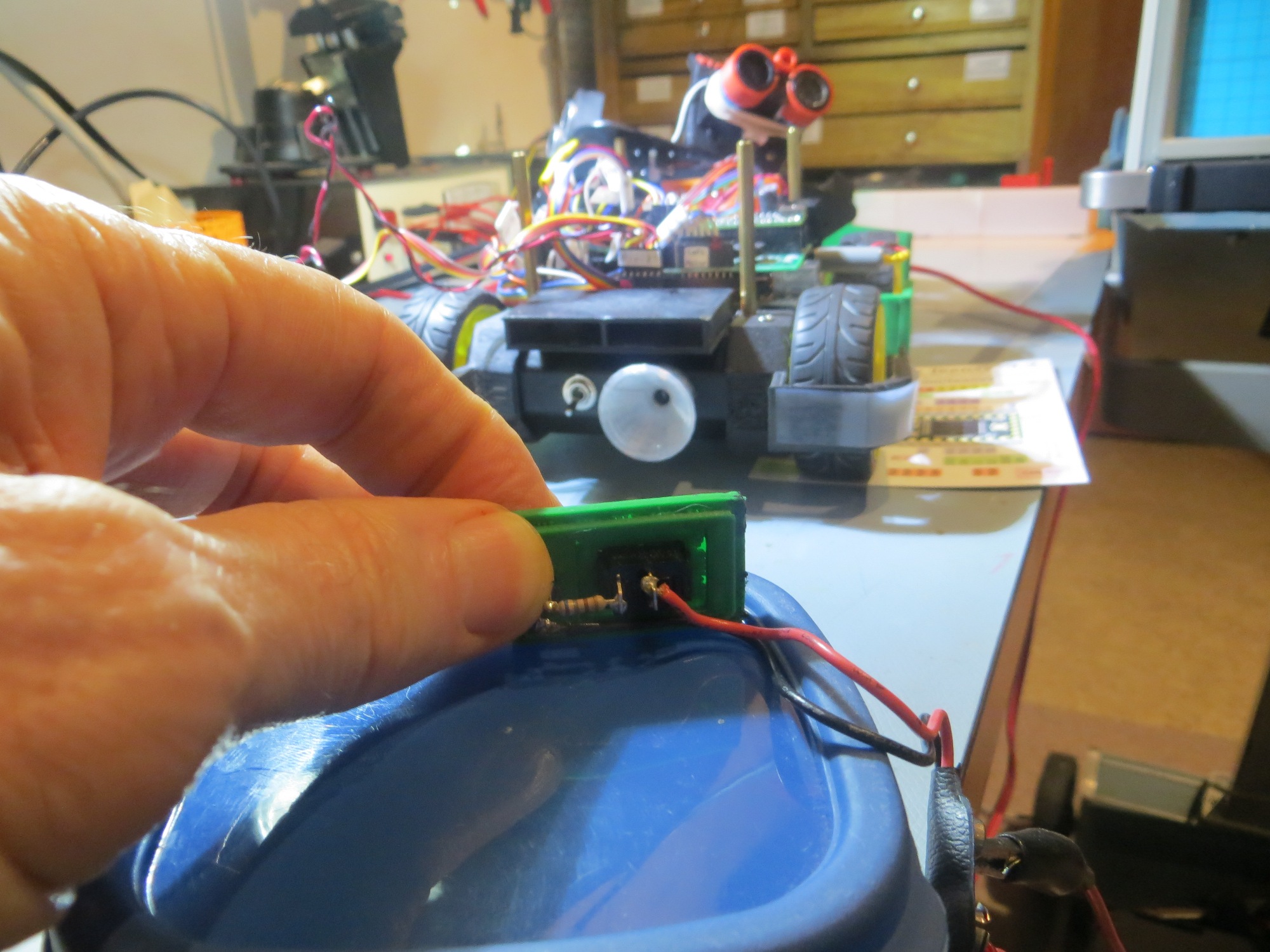
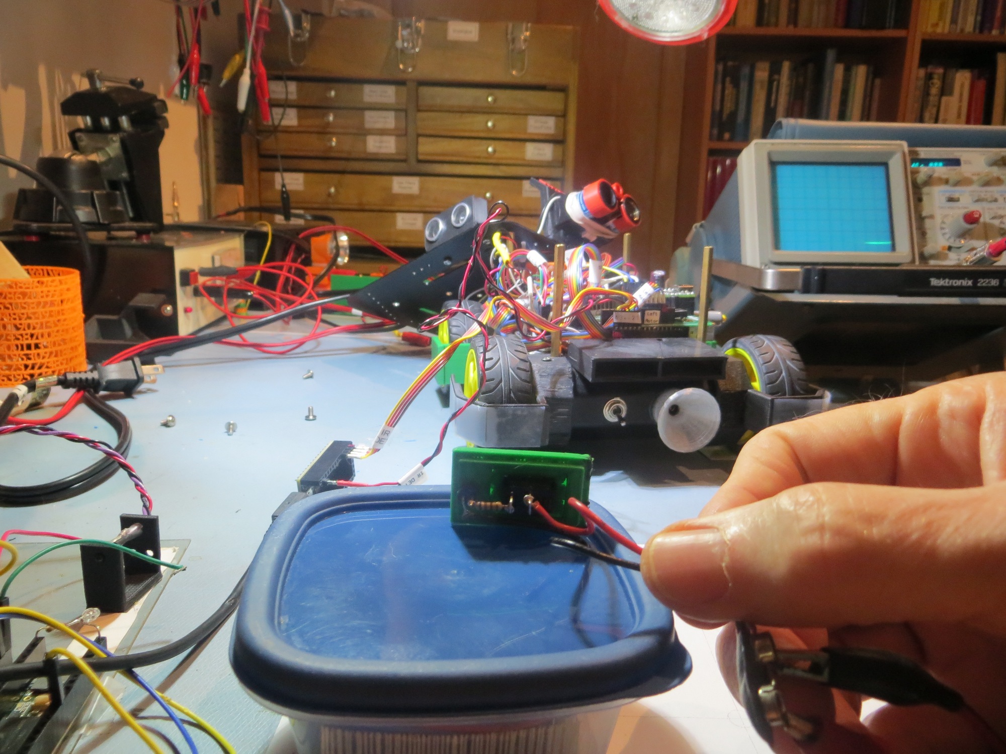
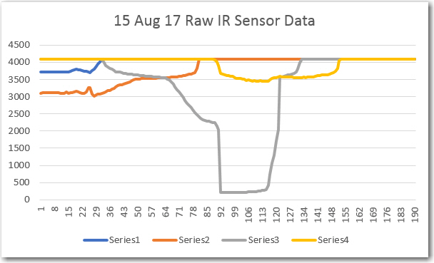
Raw IR sensor data as received by the Teensy 3.2
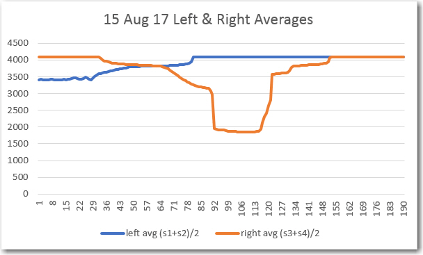
Left & Right averages
So, the IR sensors are indeed alive (maybe too alive in the case of sensor #3) and working, and the A0-A3 analog inputs are verified working as well. Also, in this very rough test, it is apparent that the responses from all four sensor overlap to form a continuous field of view, and that averaging the two left and two right IR sensor data sets also works.
Next, I moved the range out to 1m and then to 1.8m and ran the same tests, with results as follows:
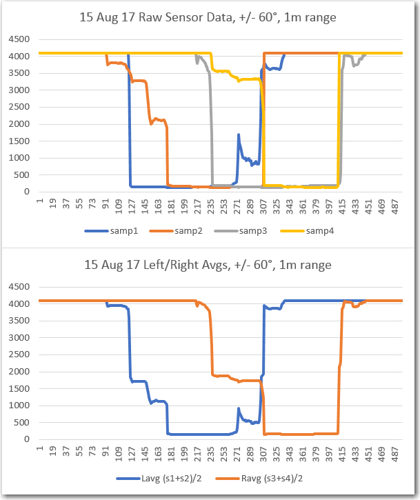
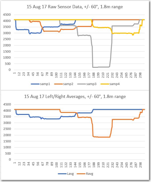
From the above results it is clear that sensor #3 is considerably more sensitive than the others.
Pingback: IR Homing Module Integration, Part V - Paynter's Palace