Posted 26 June 2017
In my last post on this subject, I had just decided to replace the Trinket transmit module with a second Teensy 3.5 to see if this would produce a more stable transmit waveform. Indeed, it did seem to be more stable, as shown by the plots at the bottom of yesterday’s post.
Today I decided to see if I could further improve the situation by getting a closer match between the transmit and receive frequencies. To do this I modified the demodulator program to output a square wave at what it thinks is the right frequency, and compare it to the waveform being used to drive the IR LED. If I can get these to match exactly, then there will still be a phase offset, but it will be a (mostly) constant factor.
The starting point for this effort is shown in the following short video, taken several eons (OK only 10 days) ago on June 16.
With this as the starting point, I started first by tweaking the transmit frequency. For this test, I triggered the scope on the receiver square wave signal, and tried to stop the drift of the transmit waveform. After a while I got pretty close, but couldn’t get it stopped. This was more than a little bit frustrating, as I thought the Teensy much higher clock speed should provide commensurately better resolution using the Teensy 3.x-specific ‘elapsedMicros’ type.
So, back to the inet for some more research. After an hour or so I found this post, and buried in the middle of it was a reply by PaulStoffregen (creator of the Teensy line) that noted that
The proper way to get repeating on a 1000 us interval is this:
Code:
If you set “sinceLastRead” to zero, you could “lose” any increment it makes between the time your “if” condition runs and the time it’s written. An interrupt might occur, for example. By subtracting 1000, and increment it’s made will be preserved. Software latency can still cause jitter, but overall you’ll get the correct rate, even if interrupts delay the write to sinceLastRead.
I had been setting my elapsedMicros variable to zero, so I decided to try using Paul’s technique to see if the timing accuracy improved at all. When I did, suddenly I was able to get the transmit and receive frequencies to match very closely, as shown in the following short video clip
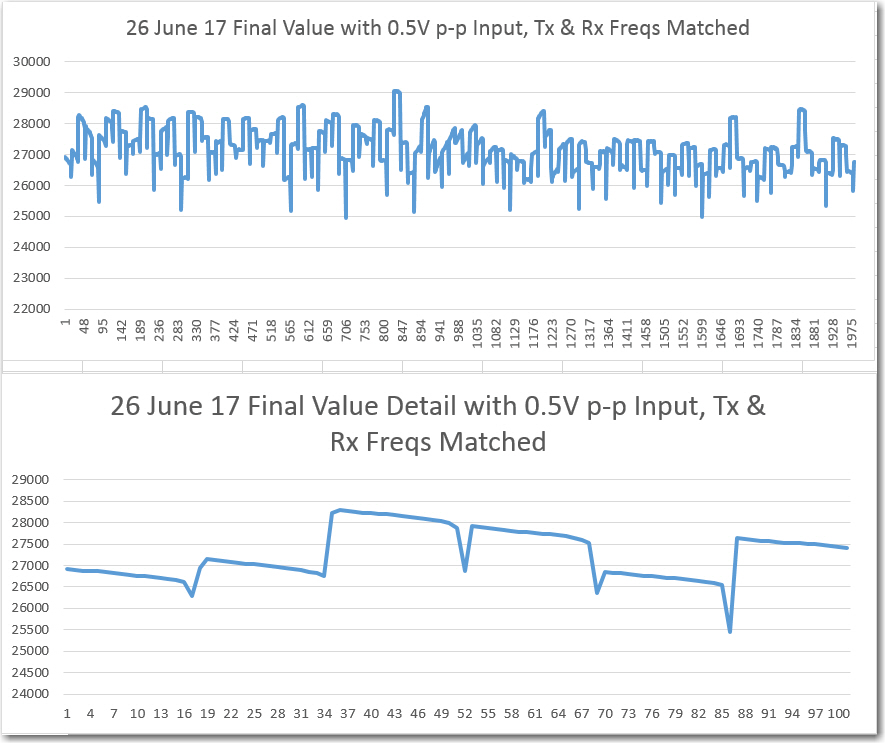
After seeing this miracle of timing, I decided to run another set of ‘final value’ plots in Excel, with the following results


These plots seem a lot more consistent than before, and a lot less ‘spiky’, so maybe I’m making some progress. However, friend and mentor John Jenkins’ comment was “still something wrong – magnitude is off” – rats! ;-).
Stay tuned,
Frank
Pingback: IR Modulation Processing Algorithm Development – Part XII - Paynter's Palace