Posted 22 March 2017
This last weekend was devoted to a whirlwind visit by the St. Louis family, which includes my 13-year old, growing-like-a-weed, 3D printing enthusiast grandson. So, I didn’t get a whole lot of time to work on Wall-E2’s problems, as Danny basically took over my entire lab ;-). So, now that the horde (can one 13 year-old kid constitute a ‘horde’?) has departed, I can get back to some sort of normalcy and make some progress.
At the end of my last post on this subject, I had concluded that I needed to go back and verify the details of the IR homing hardware and software, as the results I was getting didn’t make sense. So, I set up some experiments where I could carefully watch the raw output from all 4 IR detectors, and the changes from physically blocking one IR LED at a time. This experiment convinced me that something was definitely wrong with the hardware; at least one detector appeared to be dead, and it also looked like blocking one detector affected the outputs of more than one – strange!
So, back to the hardware; After dismounting the combined charge status display panel/IR detector module and separating the two, and physically inspecting the IR detector module I found a bad solder joint (what – a bad solder joint!? I never make bad solder joints! – must have been someone else!) on one of the detector connections to the interface header.
After repairing the bad solder joint, I carefully worked my way through the cabling maze on Wall-E2 to the microcontroller end of the IR detector cable, to verify proper connection on that end. The connections looked good, so I did some more testing, only to find that one of the IR detector outputs appeared to be dead – it’s analog reading stayed around 4-500 no matter what I did. Some more physical inspection revealed the problem – my 4-pin IR detector cable was connected to A2-A6 on the Mega board, but I was reading A1-A5, so the A1 input was essentially ‘open-circuit’ – oops!
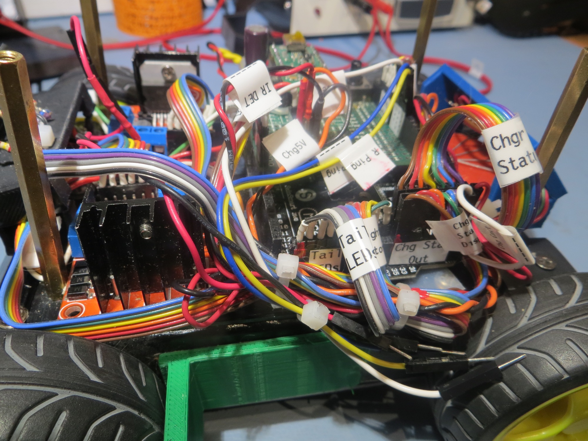
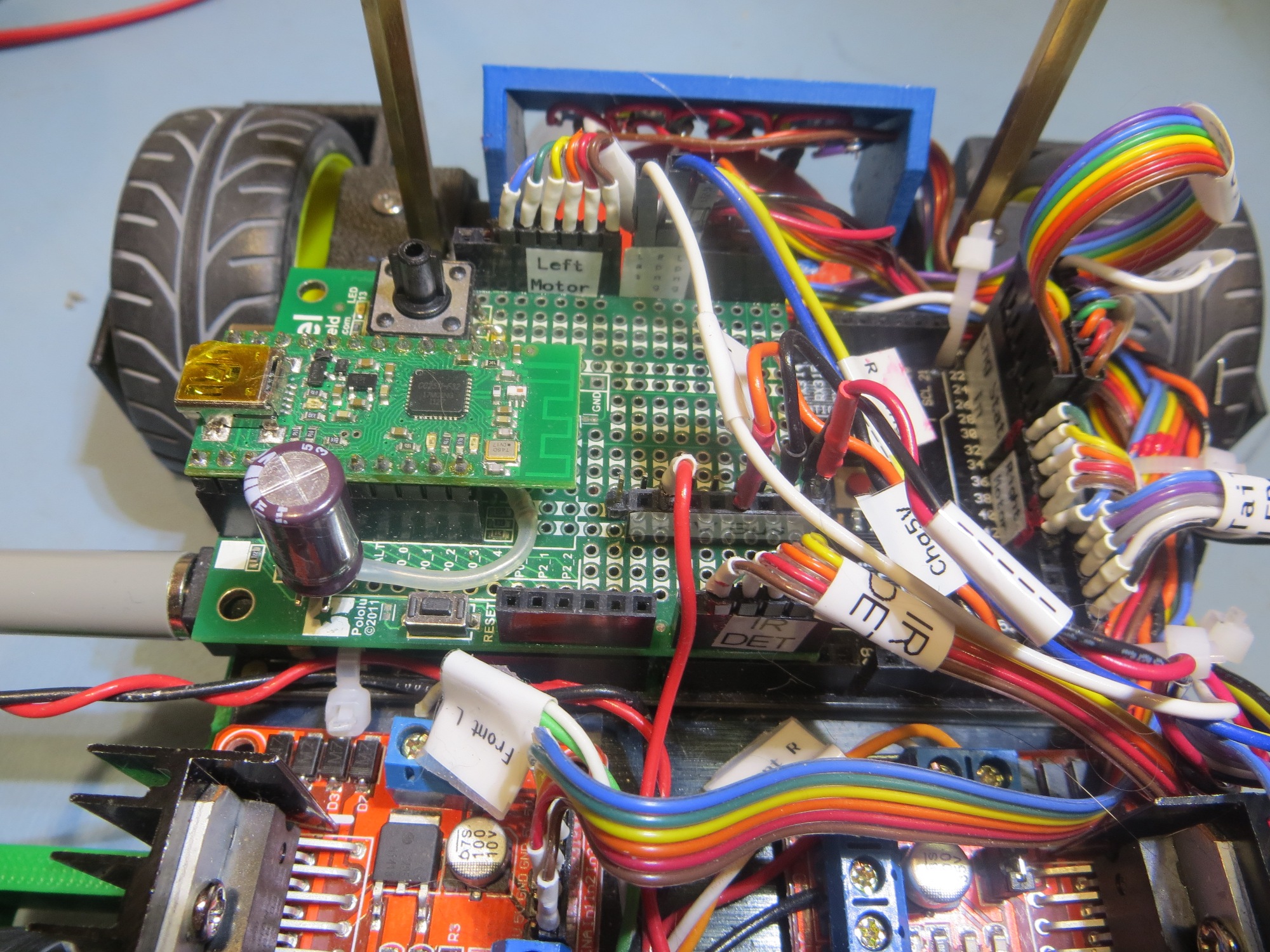
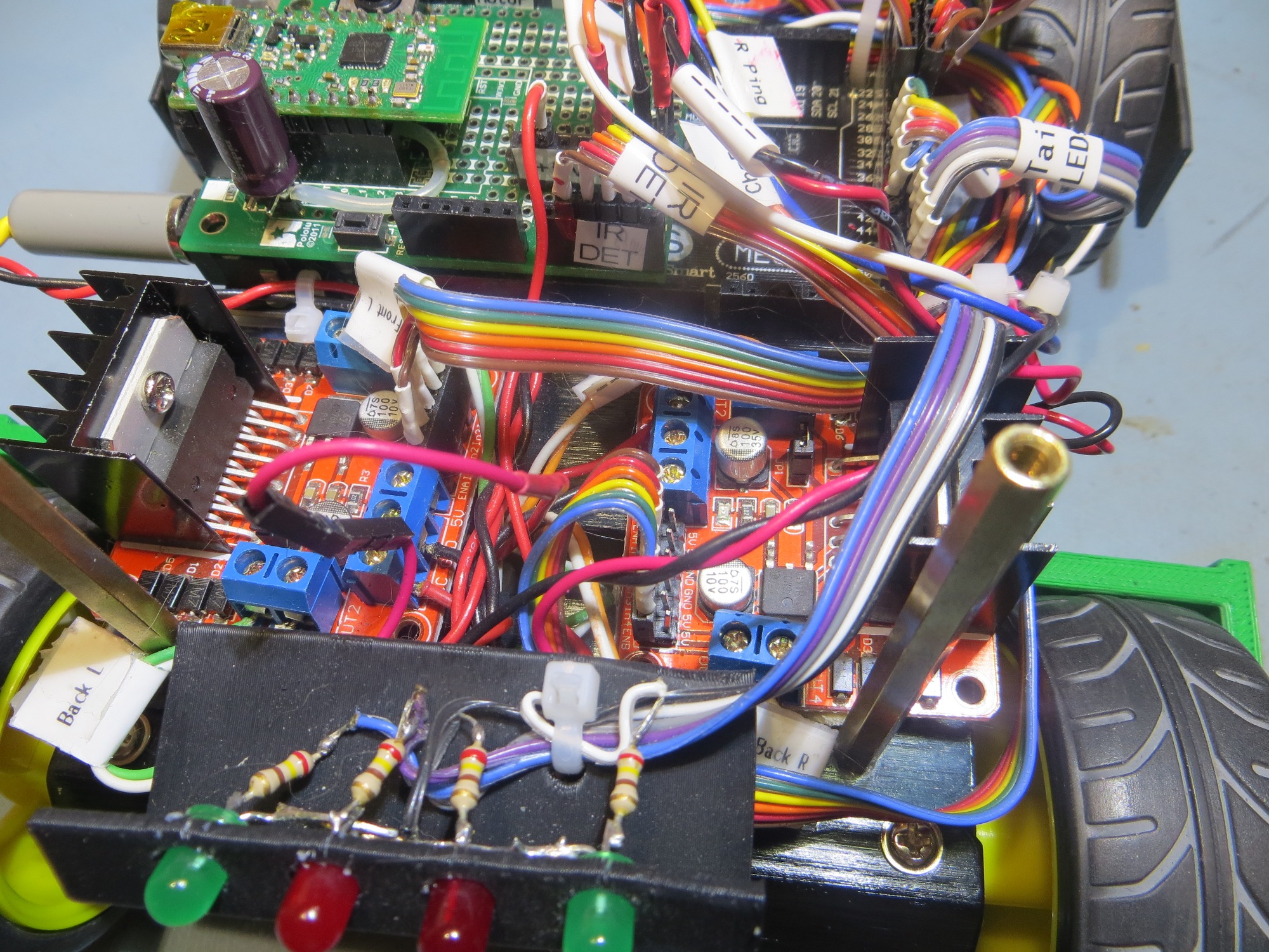
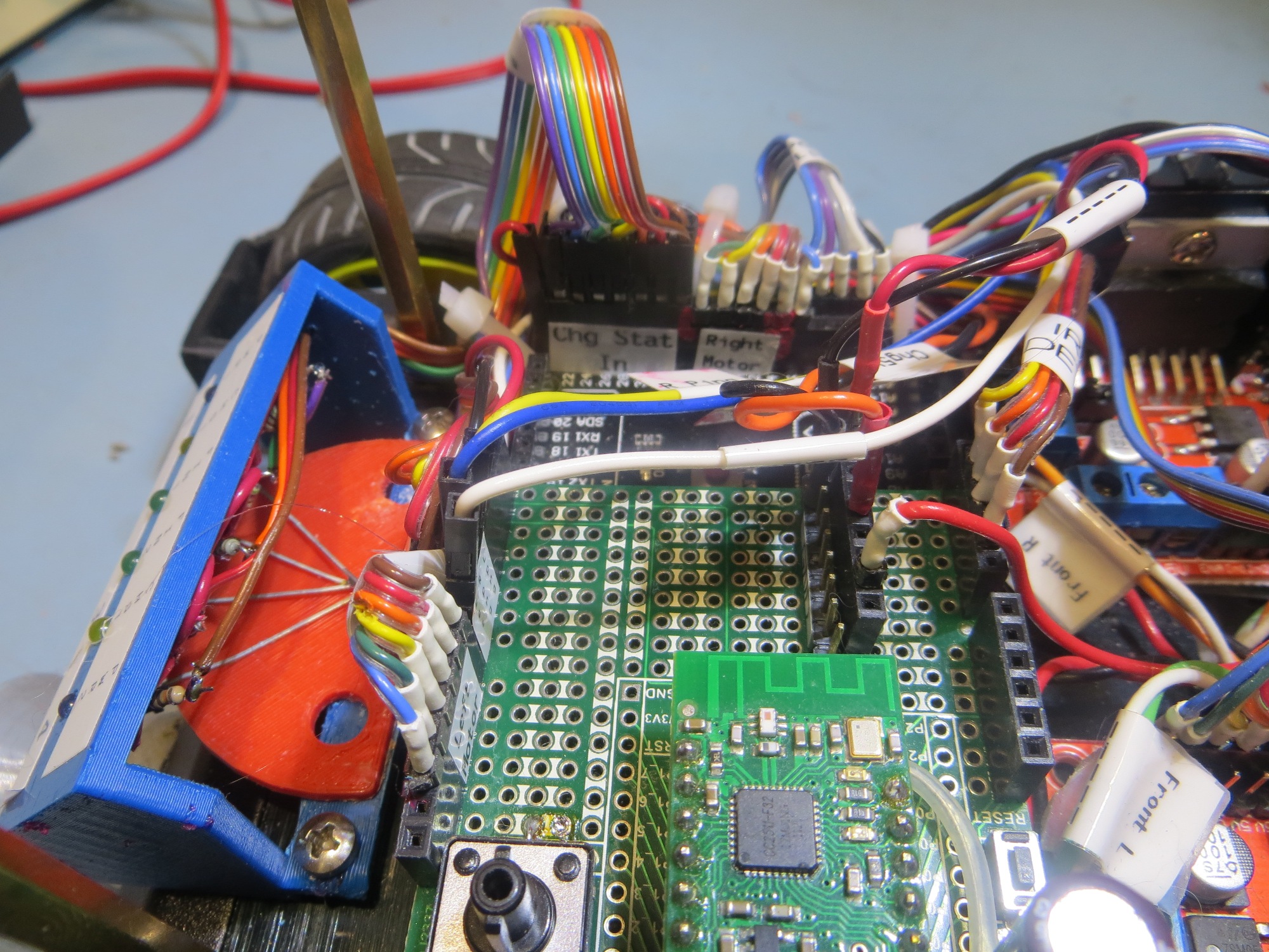
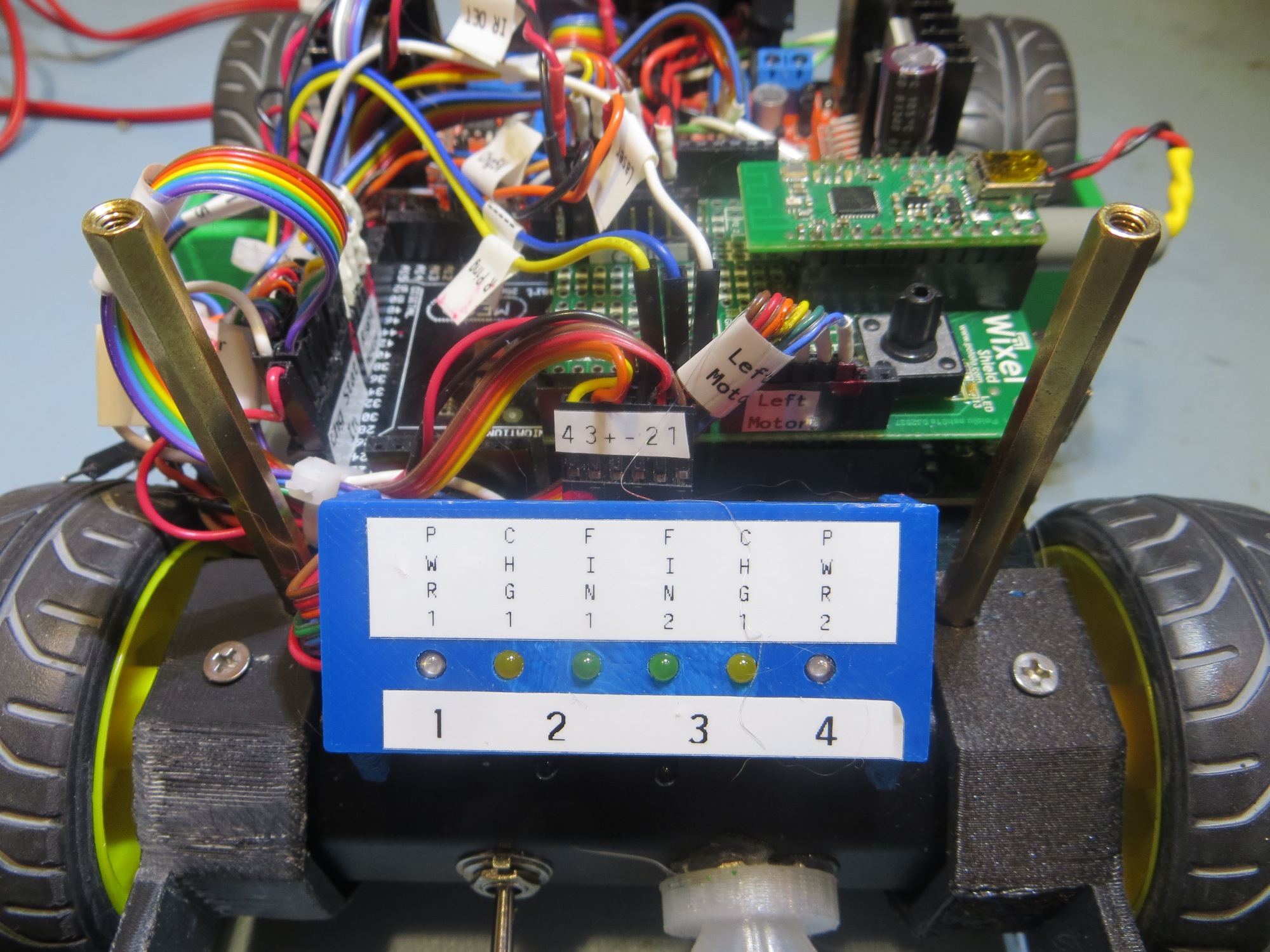
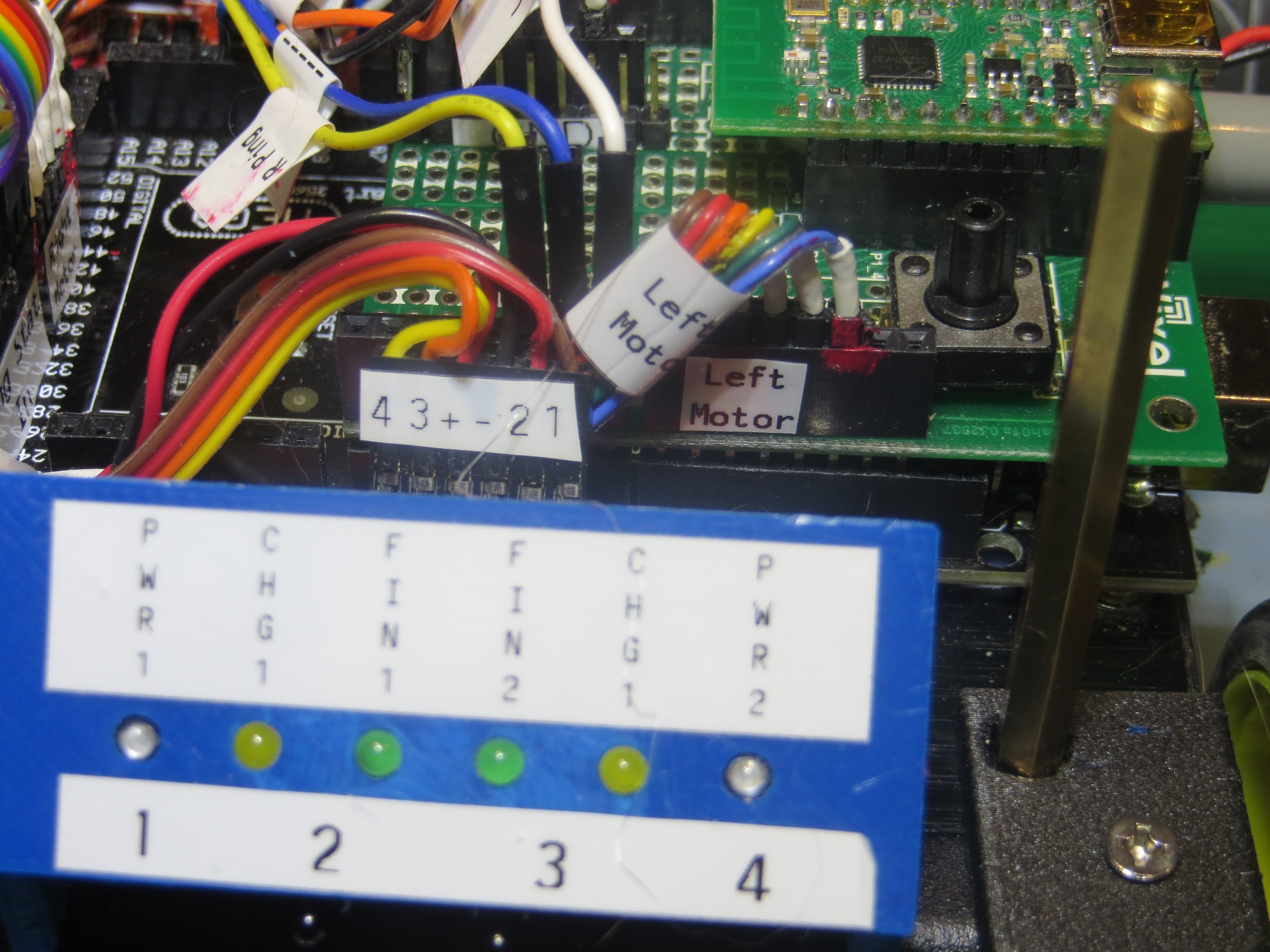
After fixing this booboo, things started to perk up and act a *lot* more normally! ;-). However, instead of immediately going back to testing mode, I decided that I needed to get serious about labeling and indexing cables (I use red fingernail polish to index one end of each connector to the corresponding microcontroller pin) and connectors on Wall-E2, so I would have less trouble in the future with the large number of ribbon cables and loose wires now festooning the robot. Fortunately I have my wonderful Brother P-touch label maker to help me with this task. As an aside, if you are a ‘maker’ hobbyist like myself, a label maker is an absolute godsend, and I can’t recommend the Brother P-touch highly enough.
After my labeling and cleanup campaign, Wall-E2 is a lot more self-documenting, as shown in the following photos
