Posted 09 Jan 2017
It’s been a while since I have posted on my evil plan to set my wall-following robot free to roam the house terrorizing cats, all without the need for charging assistance from mere humans ;-). I have made a lot of progress – but unfortunately not all of it has been positive :-(.
Charging Platform:
I was able to complete and print the final design for the fixed part of the charging platform, as shown in the following images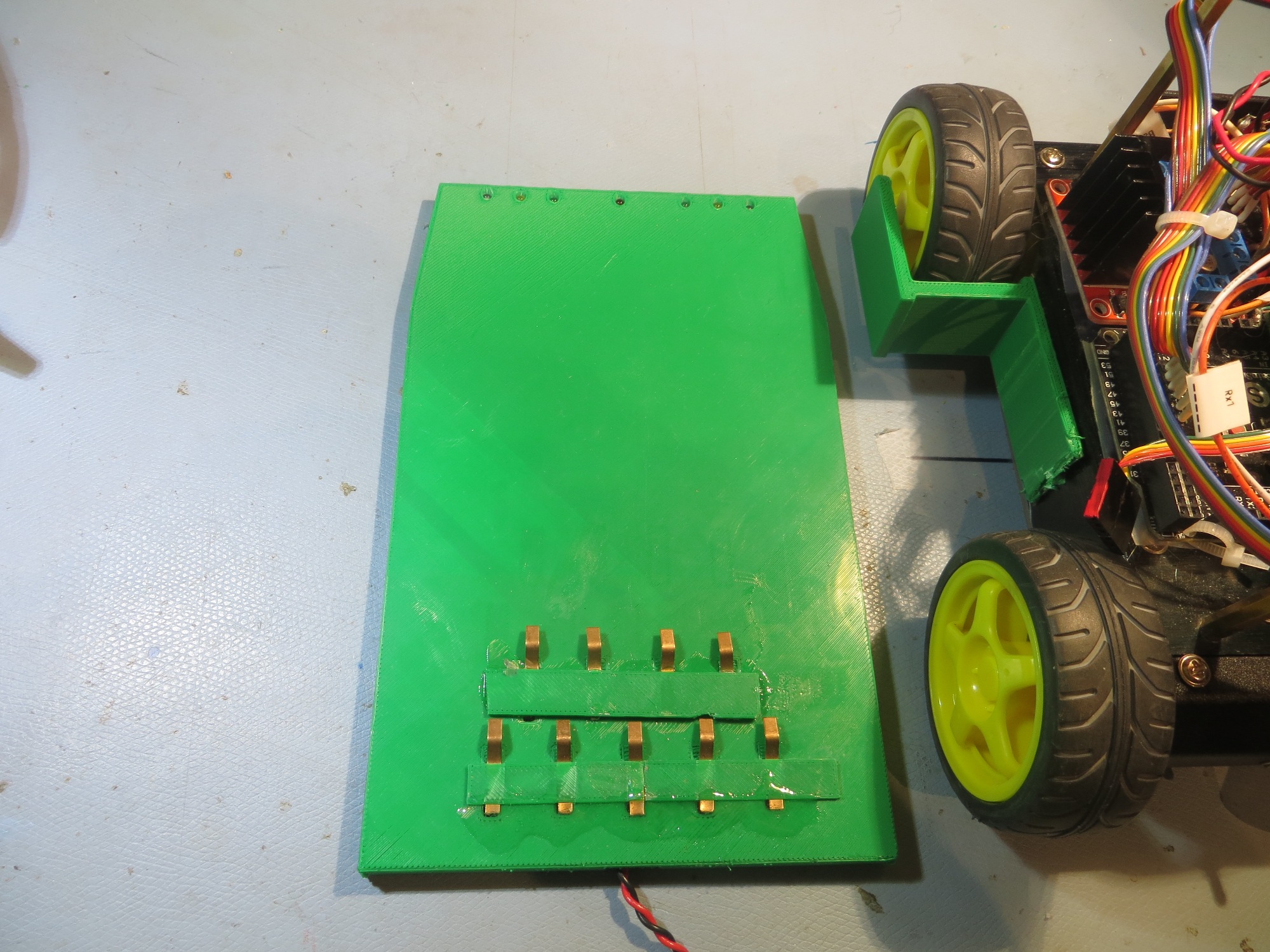
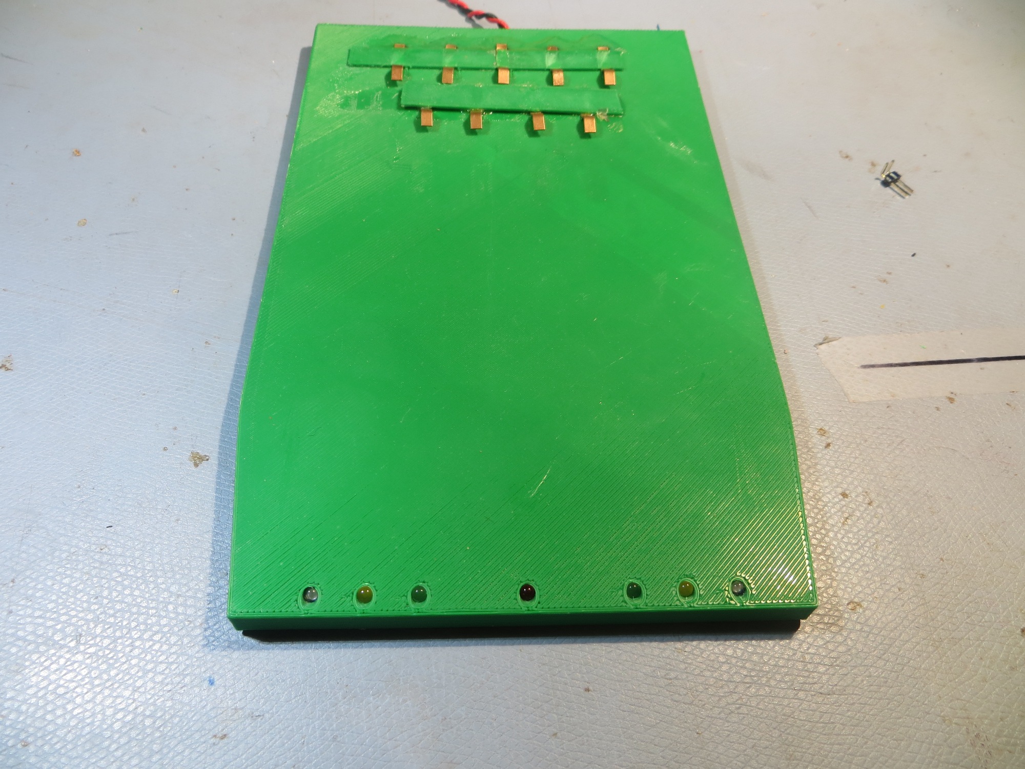
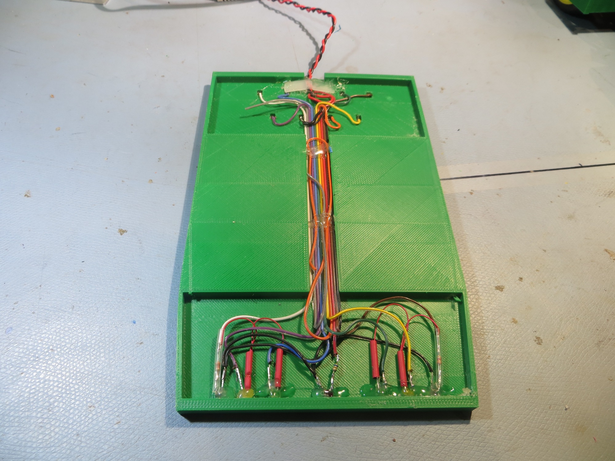
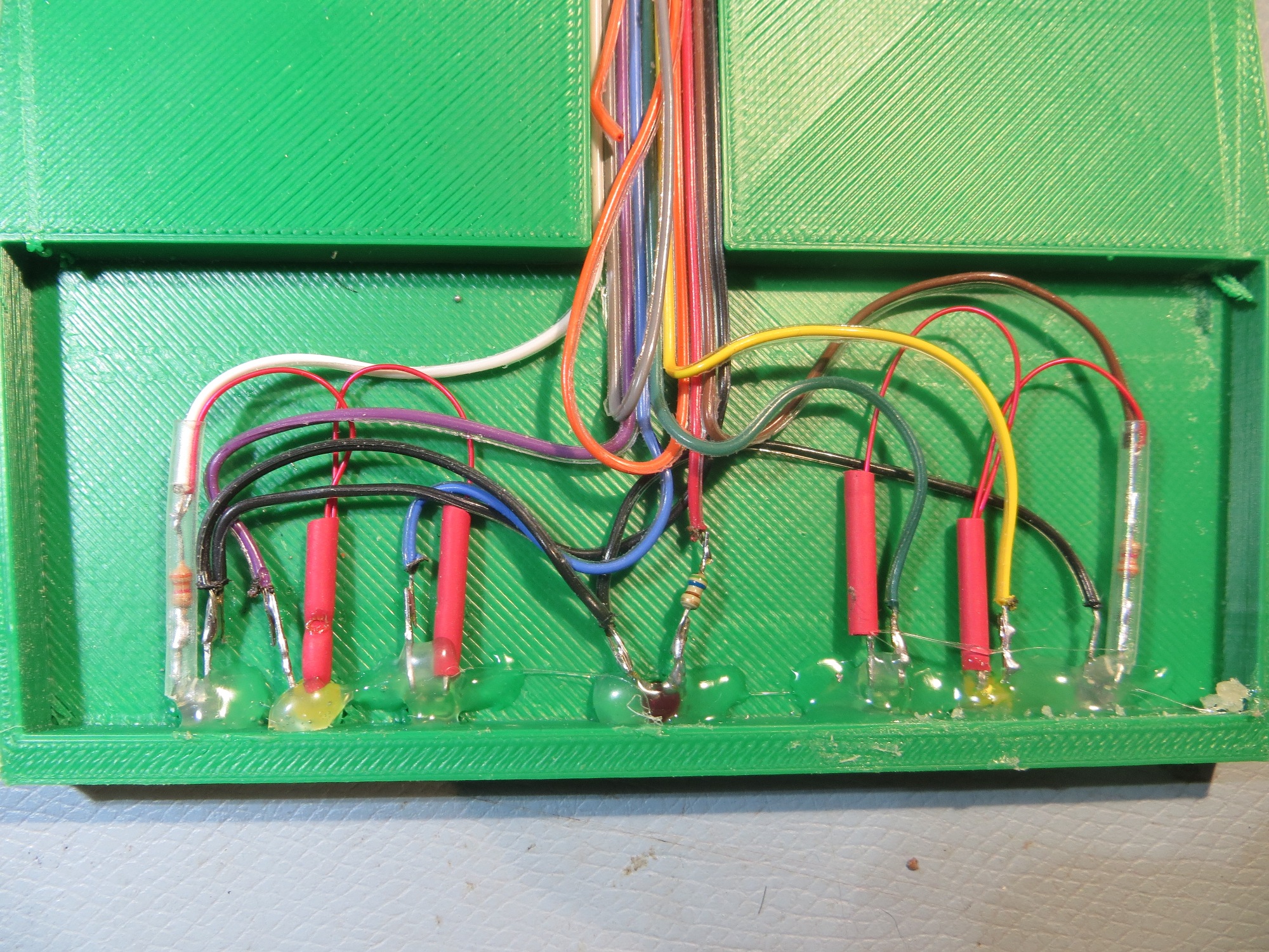
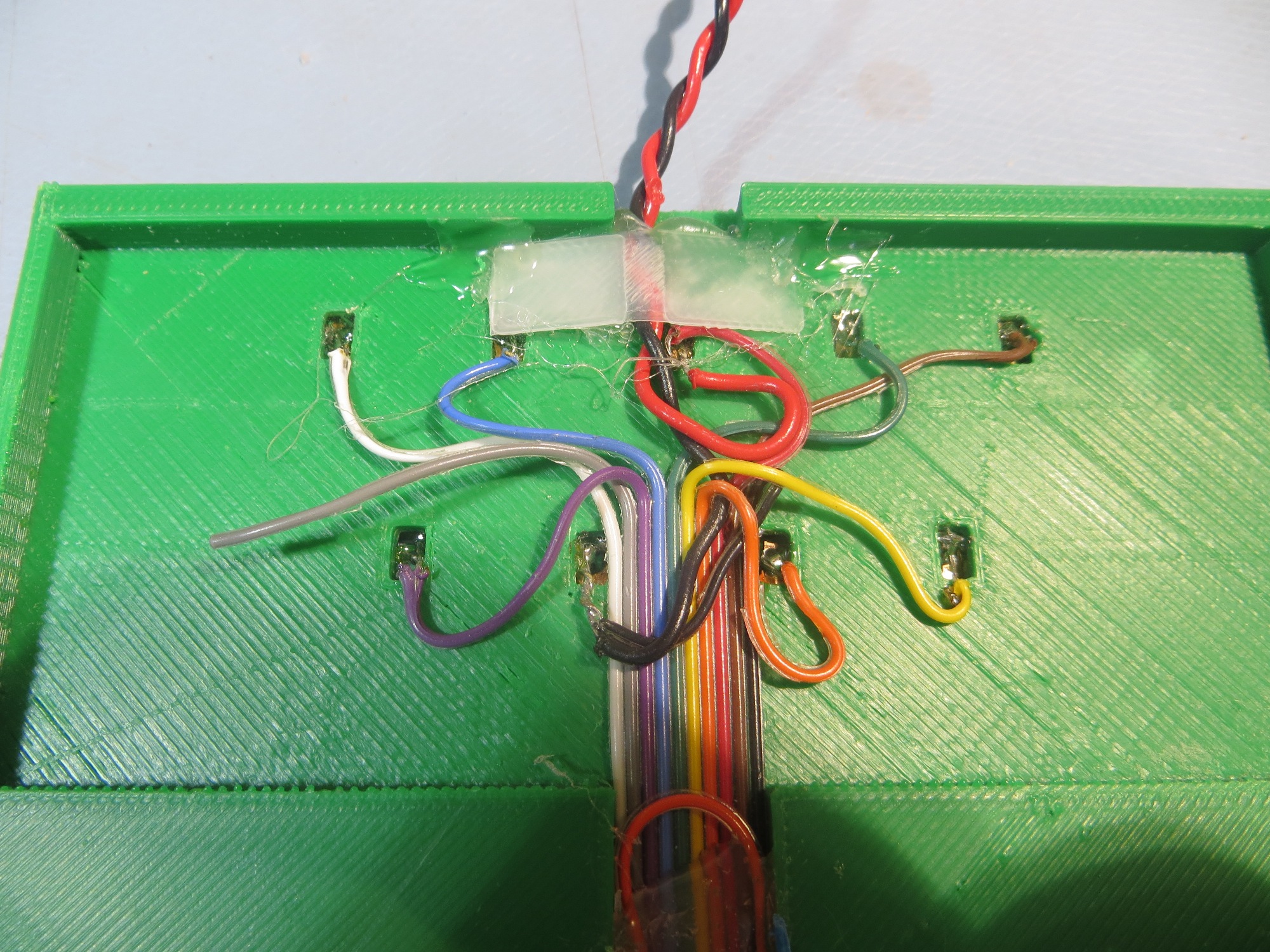
The idea was that the robot would be captured by the lead-in rails and roll over the charging platform to a stop – thereby connecting to the platform via the contact array. The status LEDs would be visible to a person standing behind the robot. Unfortunately, when I got everything all hooked up, the beryllium-copper finger-stock fingers proved too stiff to allow connection across the contact array; a couple of fingers were just a bit higher than the others, and the robot wound up suspended from these, and not making contact with the others – BUMMER!!
So, it was (literally and figuratively) back to the drawing board on the whole charging station idea – what to do?
TE Connectivity Flexible Contacts:
When I first thought of the idea of a charging station with flexible contacts and an under-robot contact array, I did a fair bit of web research on flexible contacts, and wound up with the idea of using individual fingers from a length of beryllium-copper finger stock, which is readily available on eBay. Now that this option has been ruled out, it was back to the web again for more research. This time I found a company called TE Connectivity, and they have a line of flexible contacts for use in connecting PCBs to cases in mobile devices, among other things, as shown in the following images. They have a huge variety of contacts, so I was able to find four good possibilities with uncompressed heights between 3 and 4mm. Even better, The TE connectivity folks let me order samples – yay!!


I practically wet my pants when I found these, as I think they are the answer to my prayers; otherwise I would probably have to abandon the entire charging platform/contact array idea.
Automatic 5V Charging Connector Mating Option
When I installed the new battery pack in Wall-E2, I also re-installed the 5V power jack that came with the original kit. I figured that I could use this jack to manually charge the batteries until I got the human-free option working. While waiting for the connector fingers from TE to arrive, I started thinking that I just might be able to work up a way to have Wall-E automatically drive itself onto the mating 5V plug to charge, then back off of it when finished. I had not pursued this in the past, as I thought it would be too hard to get the plug and jack lined up with any consistency, but now I was reconsidering it as possibly the only remaining option. And, since I have a 3D printer sitting on my workbench, I started experimenting with coupling ideas. The first challenge was to design and fabricate a ‘capture basket for the 5V jack, so that the initial alignment wouldn’t have to be perfect. After the normal half-dozen or so failed designs (have I mentioned how much I love the ability to do short turn-around design/fabrication cycles?), I had a design that I thought would work, as shown in the following photos.
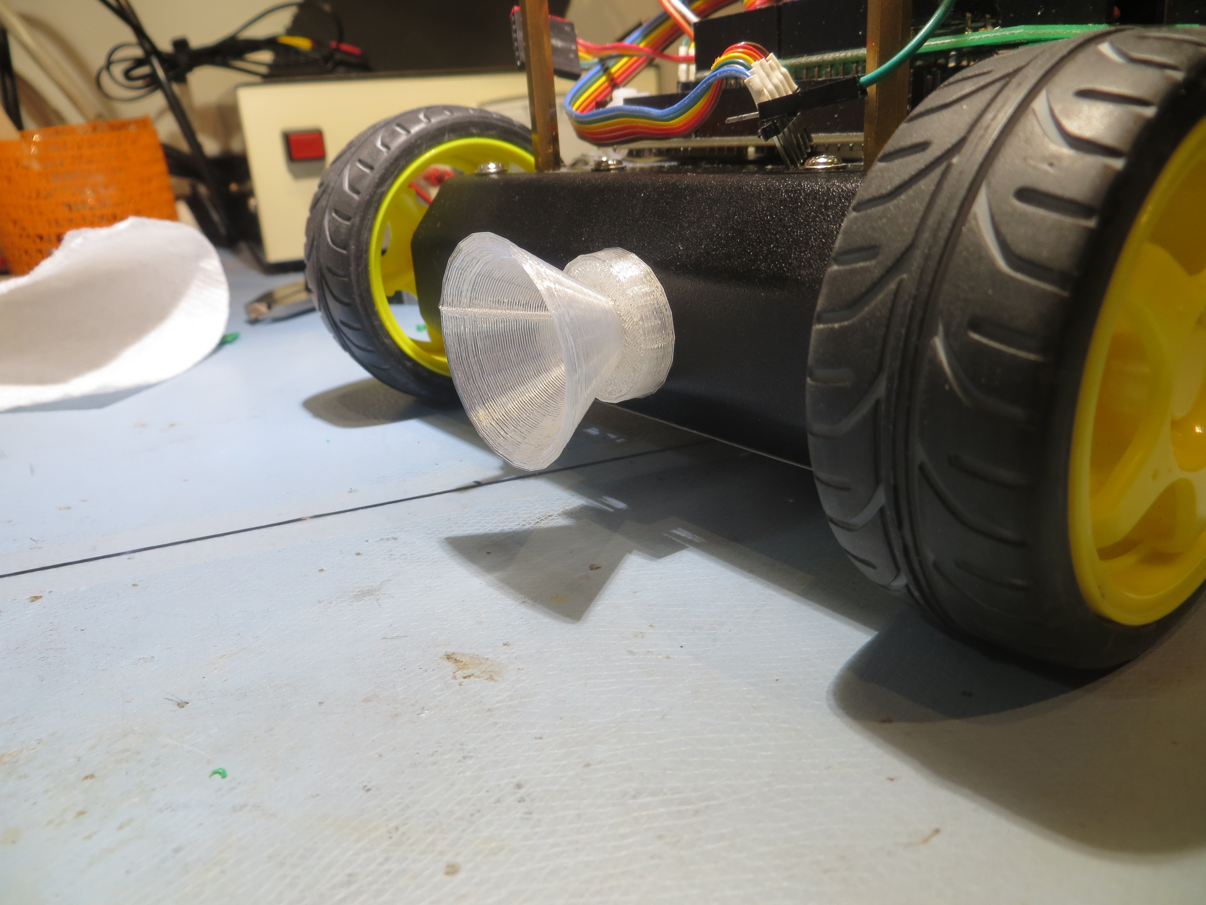
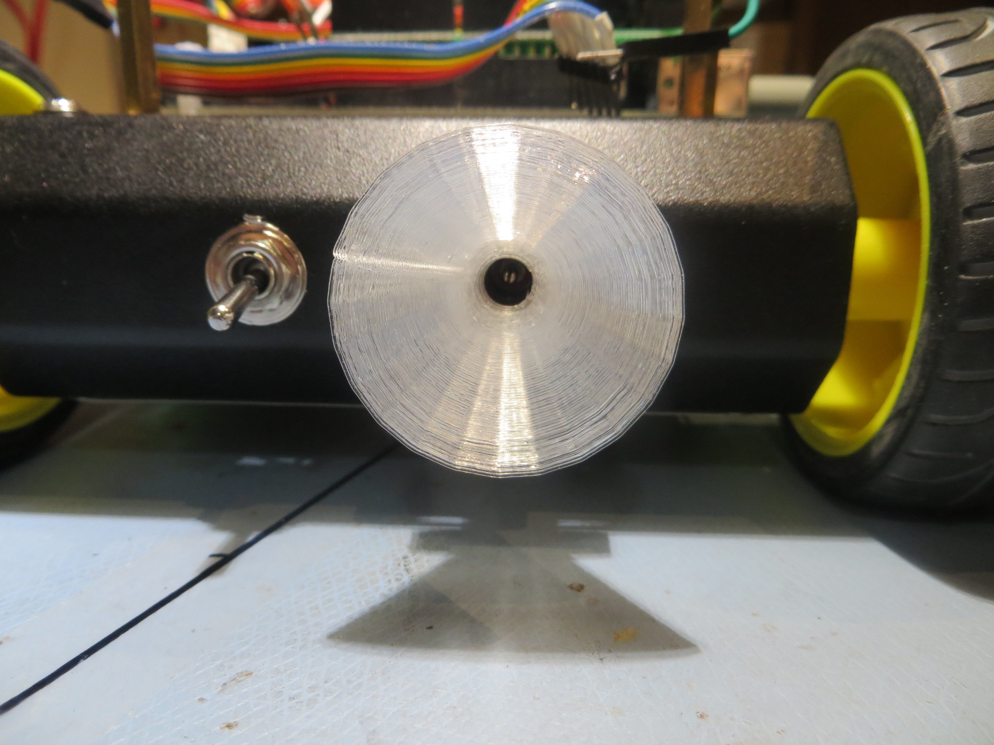
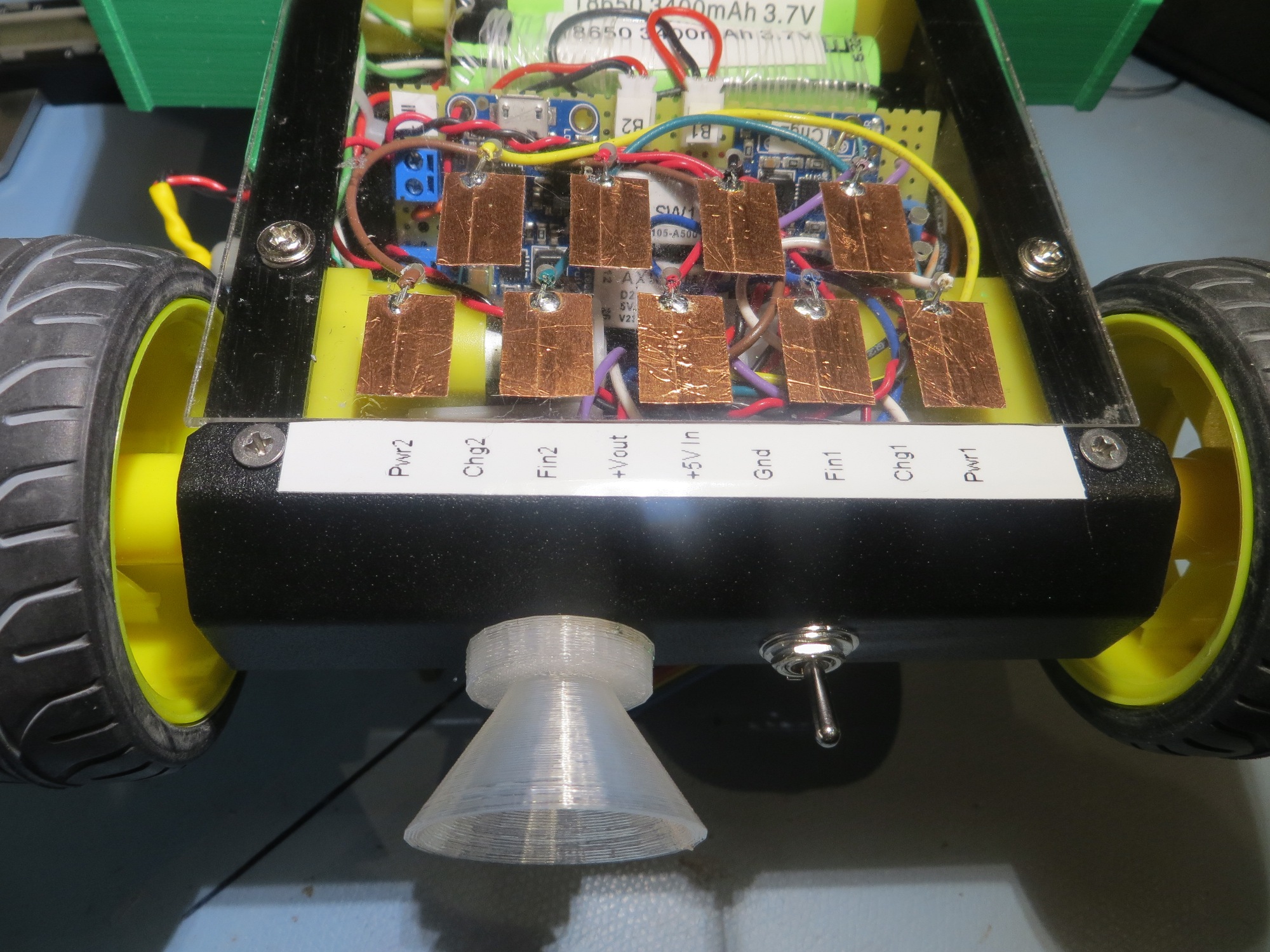
The ‘capture basket’ fits very snugly over the 5V power jack, and is designed such that the slanted sidewalls mate up seamlessly with the lip of the jack – no flat spots or corners to impede the plug on its way in. I was a little bit worried about the granularity inherent in FDM prints, but this turned out to be a non-issue, as shown below.
After getting the capture basket designed and fabricated, it was time to work on the other end – the plug probe. I already had a tentative design for a part that would serve as a stop for the robot while also providing a mount for the IR beacon LED, so I decided to add the plug/probe to this fixture, as shown below
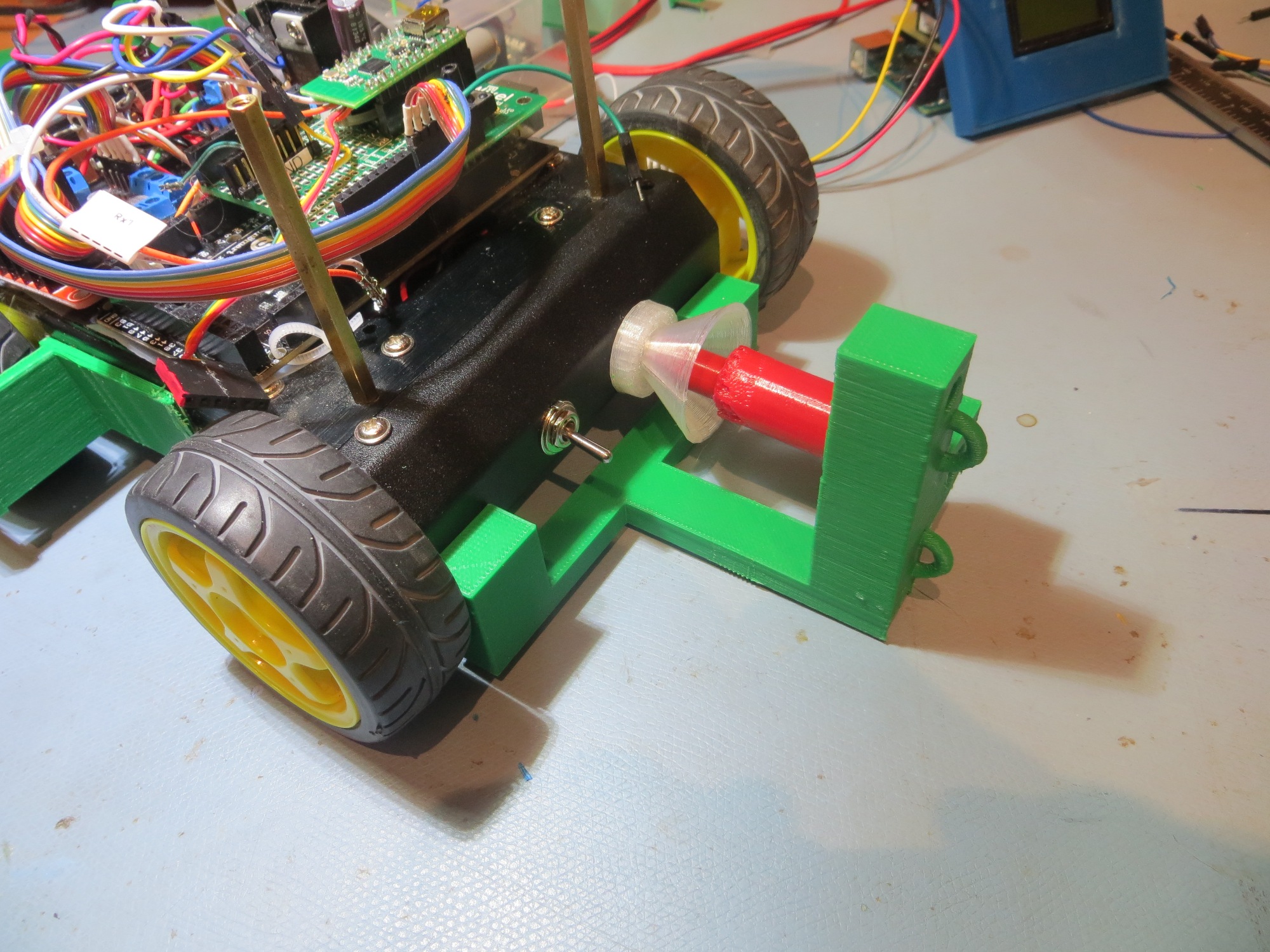
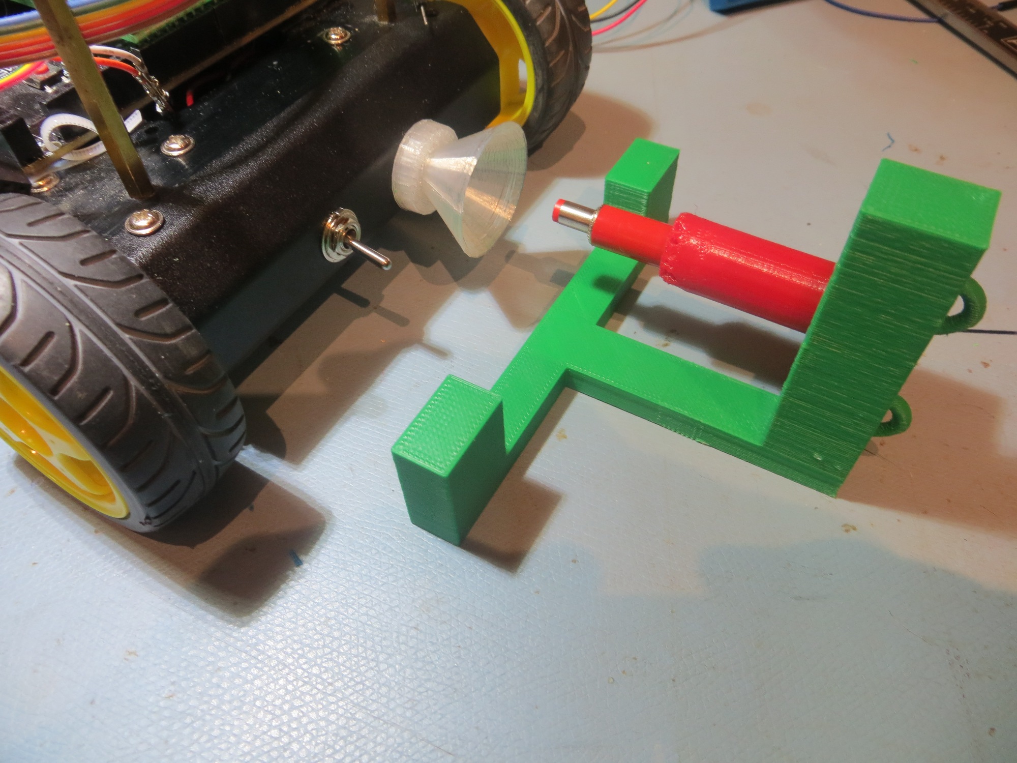
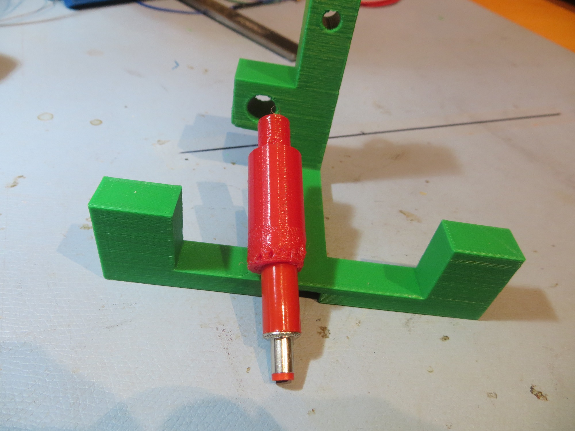
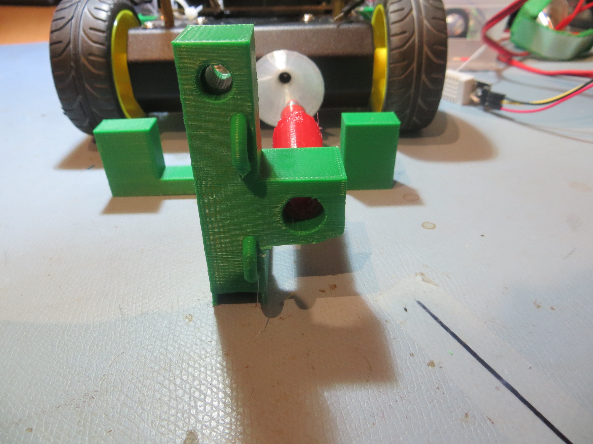
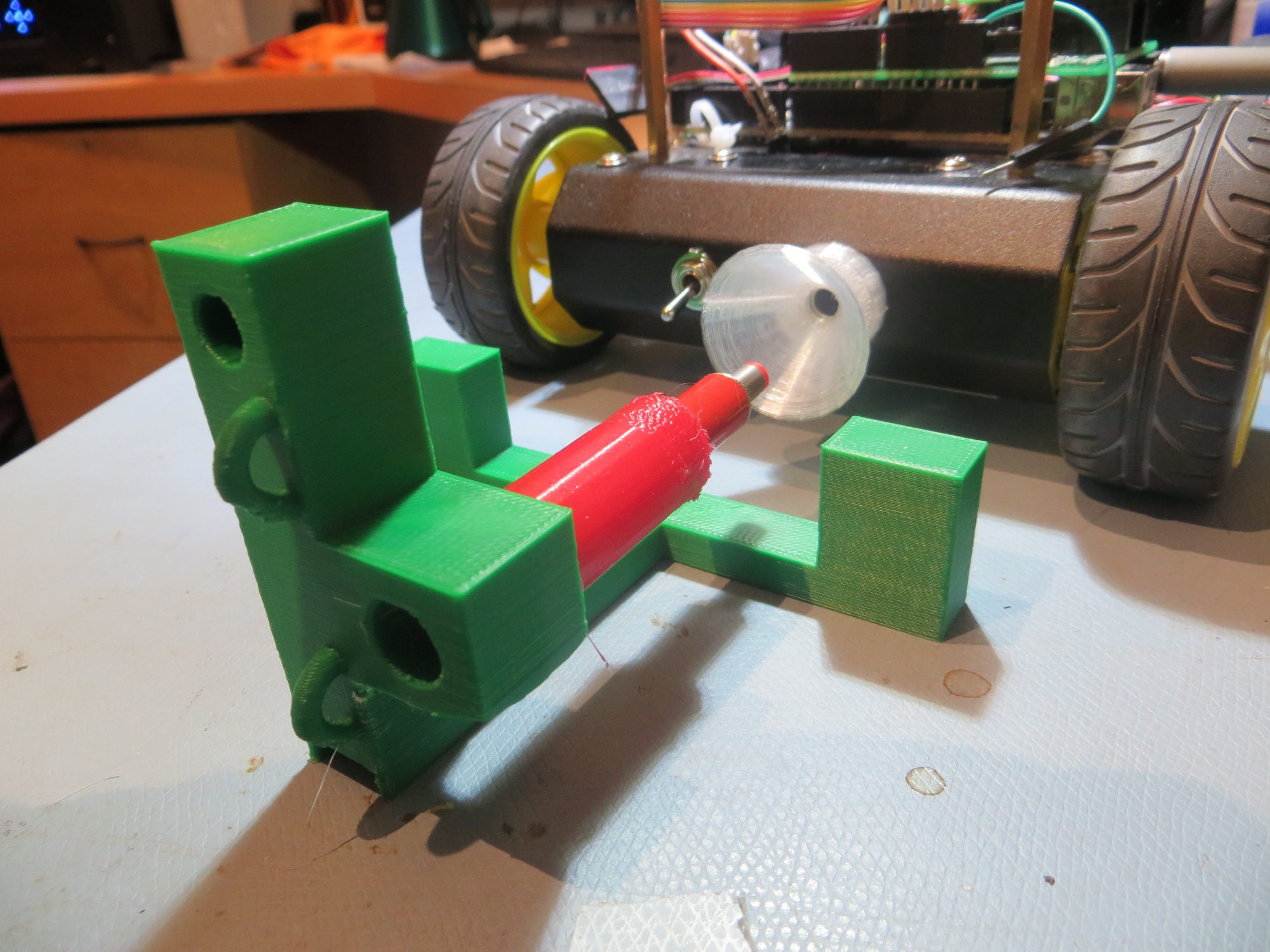
I was able to simply add a block of plastic onto the side of the original stop/IR LED holder to accommodate the plug/probe assembly. The probe was fabricated from NinjaFlex to allow for some flexibility as the plug mates with the jack. As the following video clip shows, this arrangement seems to work quite well!
So, now I have what appears to be a viable alternative to the contact-finger/contact array strategy. The jack/plug alternative has a significant drawback in that I can’t bring the battery charging status signals out for off-robot display. If necessary that can be accommodated by constructing some sort of on-robot status LED strip (not sure where I would put it, but…), but it would certainly fulfill the primary requirement of allowing the robot to feed itself, and there’s no real need to keep those puny humans informed, anyway ;-).
Stay tuned!
Frank
Pingback: Wall-E2 Charging Station Design, Part VIII - Paynter's Palace