Posted 20 Nov 2016
As the reader might recall, my grand plan for forcing the entire universe to kneel to my all-powerful Wall-E2 robot (OK, so that is a slight exaggeration – my real plan is to subject our two cats to the depredations of an always-charged wall-following robot). Wall-E2 has been wall-following for a while now, but I hadn’t been able to come up with a good idea for how to get it to locate and connect to a charging station. This all changed when I happened upon the OSEPP IR-follower module at MicroCenter, which resulted (eventually) in my 4-detector adaption of that concept. After some additional work, I arrived at a reasonably effective PID-based IR-homing algorithm for Wall-E2. So, now it is time to start working on the design and fabrication of a charging station.
Charging Station Concept:
The concept for Wall-E2’s charging station is that an IR emitter will be mounted in such a way as to lure Wall-E2 into a ‘capture basket’ formed by a set of slanted guide rails. Once in the basket, Wall-E2 will be forced up a ramp to a pedestal that will further guide the robot to a point where contacts on Wall-E2’s underside mate with contacts on the pedestal. Once the contacts mate, the motors will shut down and charging will commence. When charging is complete, Wall-E2 will back down off the pedestal and out of the capture basket, and continue its normal wall-following/cat terrorizing operations.
Using TinkerCad, which just has to be the greatest, most user-friendly 3D design platform known man, I whipped up a half-scale model of the charging station, and of the Wall-E2 robot chassis, as shown in the following screenshots.
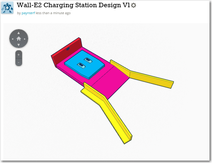
1/2-scale concept model for the Wall-E2 charging station
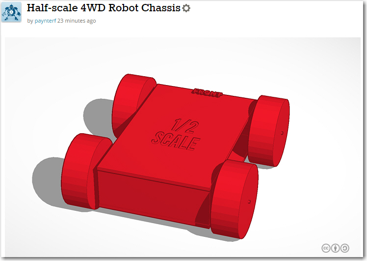
1/2-scale model of the Wall-E2 4WD robot chassis
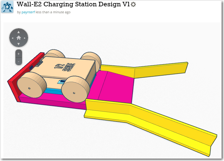
1/2-scale robot chassis on the 1/2-scale charging station model
Having the ability to put a 1/2 scale 3D model of the robot chassis on my newly-designed 1/2 scale model of the charging station is that I can immediately check for dimensional goofs (not that I ever make that sort of mistake!). Even more cool, I can easily examine internal structural issues by temporarily converting the entire robot chassis into a ‘hole’, making it transparent. This capability immediately paid off, as I was able to identify an interference condition between the station pedestal and the robot’s wheels. As shown in the following screenshot, the inside of the wheels have an interference fit with the sides of the pedestal (the dark areas indicated by the arrows on the bottom inside portion of the robot’s front/rear wheels).
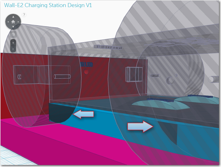
Closeup of Wall-E2 on the charging station, with the chassis model made temporarily transparent. Note the interference fit between the robot’s wheels and the pedestal (arrows)
This sort of problem is trivial to fix at this stage, since nothing has been fabricated. Gotta love that 3D modeling stuff! ;-).
When I created the charging station conceptual design in TinkerCad, I sort of eyeballed the angle of the ‘capture basket’ sides with respect to the station centerline at 20 º. As a sanity-check, I measured (in TinkerCad, it is usually convenient to simply construct a measuring stick from a box object) the opening in the ‘capture basket’ at about 158mm, or about 1.8 robot-widths. Then, going back to the videos I made during the PID tuning effort, I was able to superimpose the capture basket rails onto the last few frames of the video to see how well the capture basket dimensions fit with the observed homing behavior.
First, I captured a representative frame from my last/best ‘straight-in’ approach, and used Paint to add some lines to represent the capture basket lead-in rails. For this purpose, I measured the width of the robot in pixels (about 250 px), and used 1.5x instead of the measured 1.8x to compensate for the wheel guards on the actual robot. I called this measurement ‘Rwp’. Then I drew a 40deg capture basket with two lines starting about 0.5Rwp above and below the IR emitter location. As can be seen in the following image, the robot will indeed be captured within this capture window, at least for the ‘straight-in’ homing case.
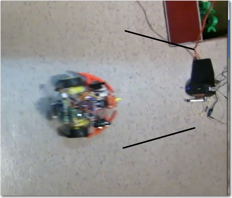
Frame from straight-in homing video, with simulated capture basket lines
Then I did the same thing for a frame from my ‘Side Capture’ video, as shown below. For this frame, Rwp is about 200, so the capture basket lines were adjusted accordingly.
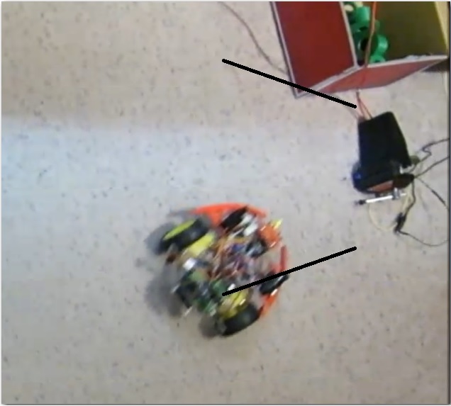
Frame from side capture homing video, with simulated capture basket lines
As can be seen in the image, the robot would have hit the right side capture basket rail. So, something will have to be done to limit the emitter beam width so that the robot can’t detect the beam unless it is more aligned with the charging station centerline.
Stay tuned!
Frank