Posted 10/16/2016
A week or so ago I participated in an OSU STEM Outreach program that showed high-school students how to build a working pulse detector circuit, using a commonly available op-amp and an IR LED/Photodetector pair. After an initial presentation, the students were given step-by-step instructions for building the circuit on a small plugboard, and I helped when students ran into trouble. By the end of the one-hour session, most students were successful, and were able to see the output LED illuminate in time with their pulse – cool!
As I helped out with the class, I was a bit shocked to see that the circuit being build by the students required two 9V batteries wired in series to create a +/-9V supply for the op-amp. At the time I just assumed somebody forgot to spec the op-amp to be one with a common-mode range including ground, and the extra battery was the ‘field-expedient fix’ for the problem. When I asked Prof. Betty Lise Anderson about this, she said that a single supply had been tried at one point, but ‘didn’t work out’ for unspecified reasons. This piqued my interest, so decided I would investigate the problem a bit further in my home lab.
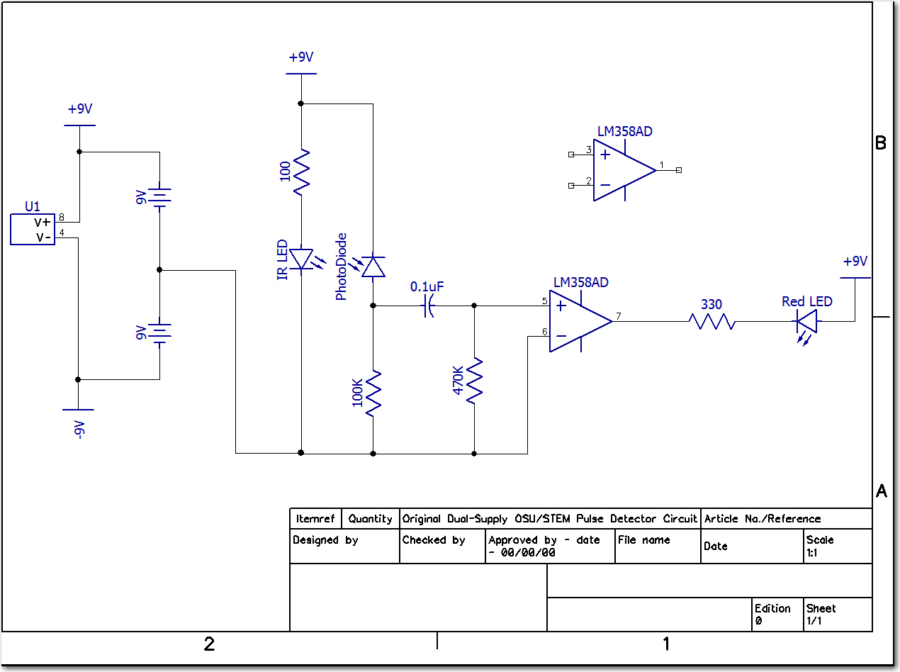
As it turned out, the op-amp being used in the students’ circuits was the ubiquitous dual-LM358 in an 8-pin DIP, and this unit does indeed have a common-mode range including ground, so the single-supply idea should have worked. Here’s the original OSU circuit (transcribed into DipTrace’s schematic capture format)

Original OSU Pulse Detector circuit. Note the dual 9V suppies
And here’s my final single-supply detector circuit

Final single-supply Pulse Detector schematic
Comparing the two, the only real difference is the addition of the 470K resistor from the inverting input to ground. In the original circuit, the inverting input was tied directly to ground, while the non-inverting input had a 470K to ground. This can be a problem, as the input bias current for the LM358 can be on the order of 100 X 10-9 (100 pico-Amp), which means that the DC voltage at the non-inverting input due to bias currents could be as much as 50mV or so. Since this is on the same order of magnitude as the photo-diode signal at this point, there is a real chance the op-amp would never toggle the output. The dual-supply setup eliminates this problem, but at the cost of a second battery.
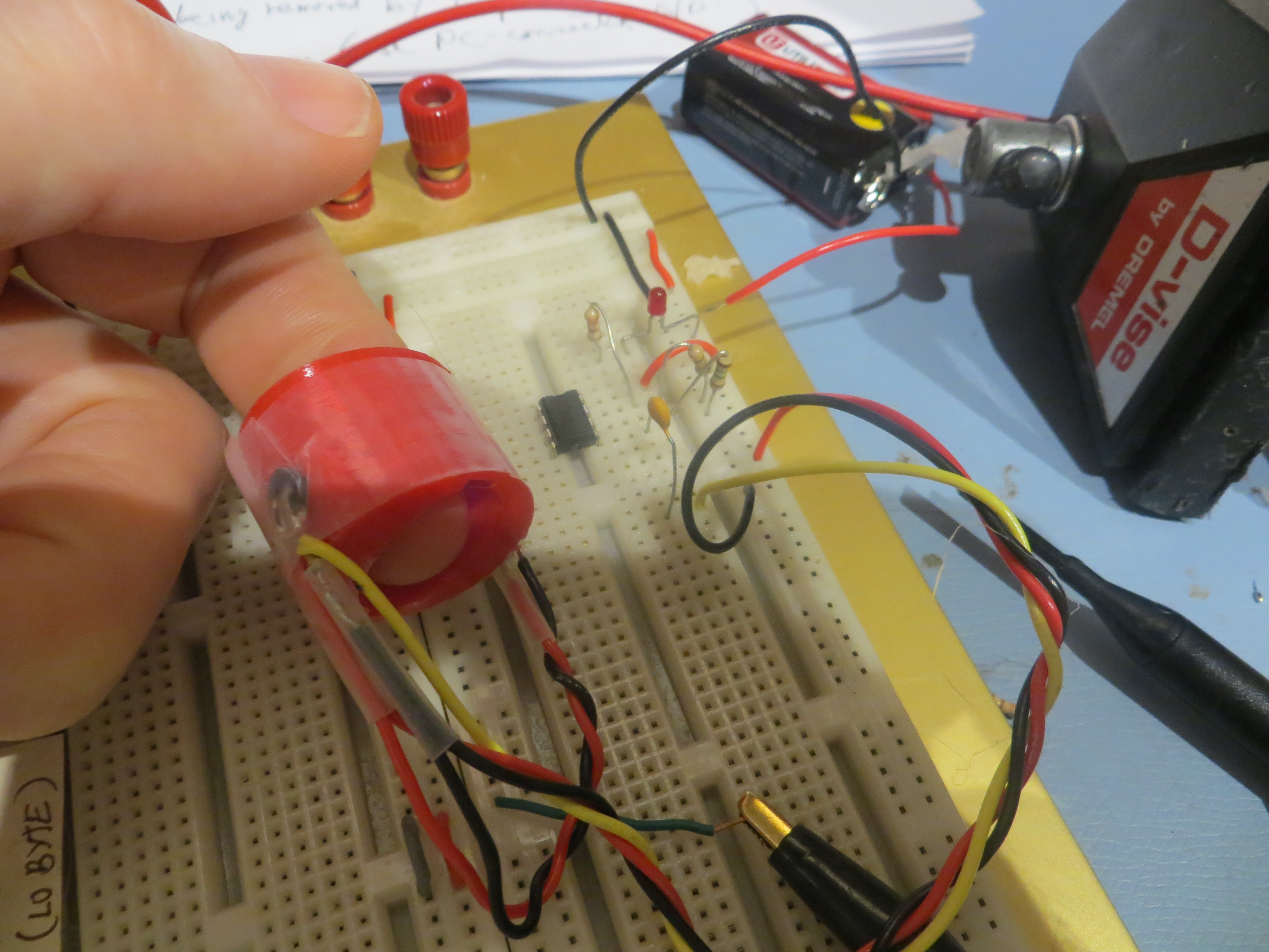
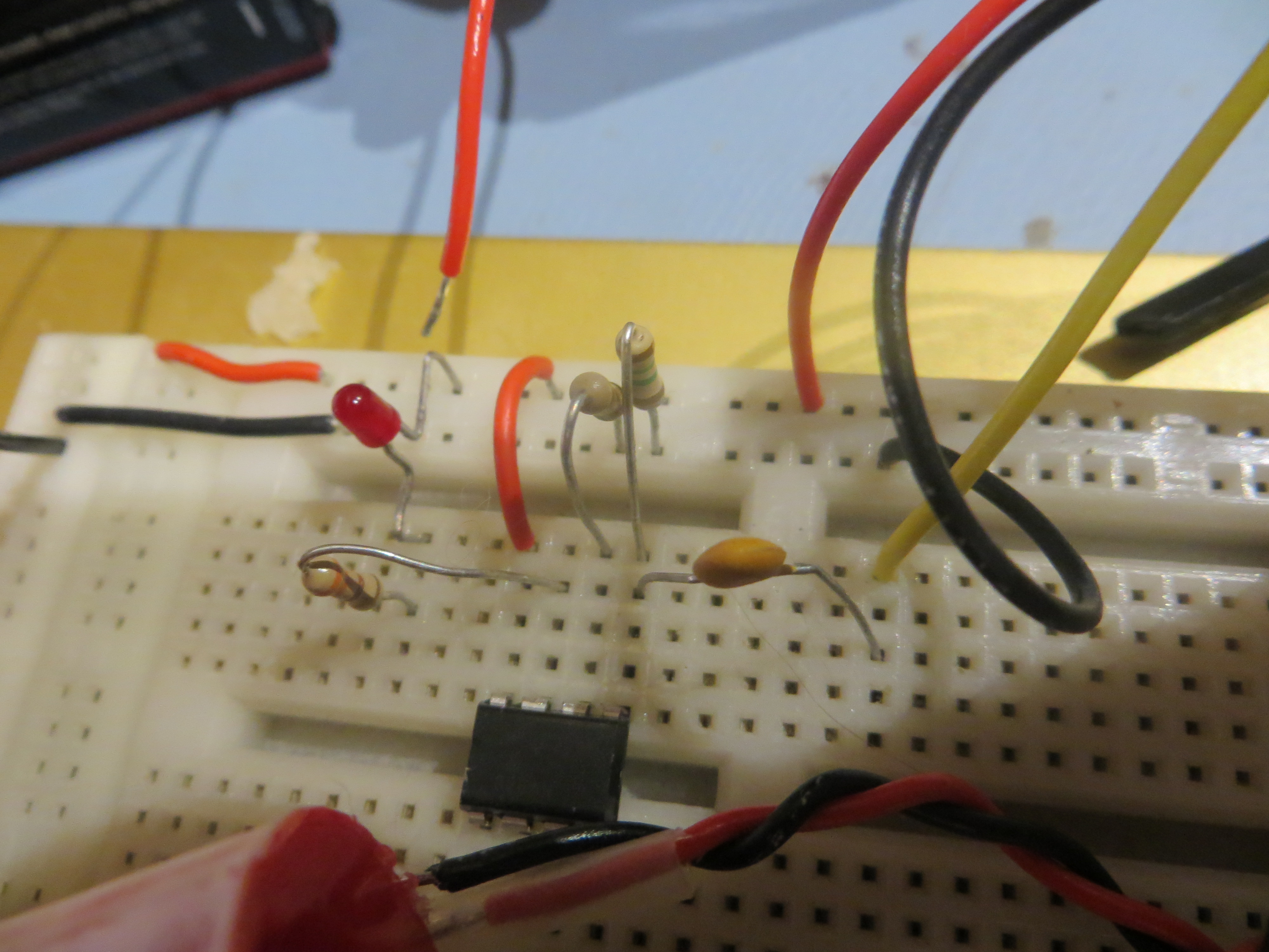
The final circuit, as laid out on my plug-board, is shown below.

Pulse Detector circuit with my 3D-printed finger socket

Final Pulse Detector circuit
And, because I can, here’s a short movie showing the pulse detector in action ;-).
Yay! A resistor is LOTS cheaper than a battery!
You also added 1.5 MOhm resistor. What does that do?
Betty Lise,
The 1.5M resistor replaces the original 470K (R3 in the original schematic). I wanted a higher value so the RC time constant of C2-R3 would be better, as I used a 0.01uF cap rather than the 0.1uF called for in the original (I have lots of 0.01s, but no 0.1s). If you stay with the 0.1, then you can go back to 470K for R3, and then the additional resistor is just another 470K.
To summarize – the 470K you see in my schematic is the added resister (from the inverting input to ground) – not the 1.5M. The 1.5M is in the same place as the 470K in your original schematic, except now it goes to ground instead of to the inverting input.
Hope this clarifies things ;-).
Frank
Pingback: OSU/STEM Outreach Pulse Detector Project, Part II - Paynter's Palace