Yearly Archives: 2015

The Duplicate Bridge ‘Blame’ Chip

Posted 6/17/2015.

A favorite topic among duplicate bridge players is just who’s to blame for a  particular screw-up.  Bridge is a somewhate unique sport in that it requires two players per side, and both players in a partnership contribute to success or failure.  A really good player can make up for many (but not all) mistakes by a weaker player, but winning partnerships require that both players minimize their mistakes. Most established (and  all successful) partnerships have developed a way of handling the blame issue in a way that doesn’t degrade or destroy the partnership.  One pair that I know describes this process  as ‘blame management’.  The idea, so they say (somewhat tongue-in-cheek) is to bid in a way that ensures that any blame for mistakes will fall on one’s partner rather than oneself.  This incentivizes each partner to bid as correctly as possible given the partnership agreement (their convention card) and the particular circumstances at the time.  Having ‘a bright idea’ and ‘going off piste’ might work, but if it doesn’t the blame will fall squarely on  the errant partner (and even if it  does work, it might incur significant blame for not adhering strictly to the partnership agreement).

I liked this idea of ‘blame management’ so much that I have tried to incorporate it into my own partnerships; I try to  get the idea of blame management out in the open early on, so my partner is (hopefully) comfortable with the idea of assigning blame in an open and humorous way, rather than letting issues fester.  Lately I have started describing this as ‘moving the blame chip from one side of the table to the other’, and that got me thinking that maybe I could use my engineering and 3D printing capabilities to fabricate an actual, physical ‘Blame Chip’.

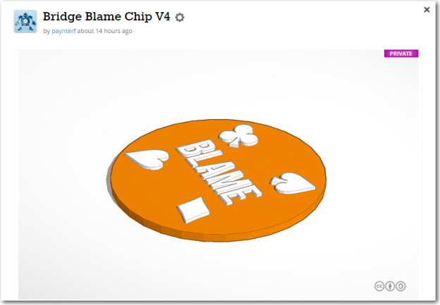
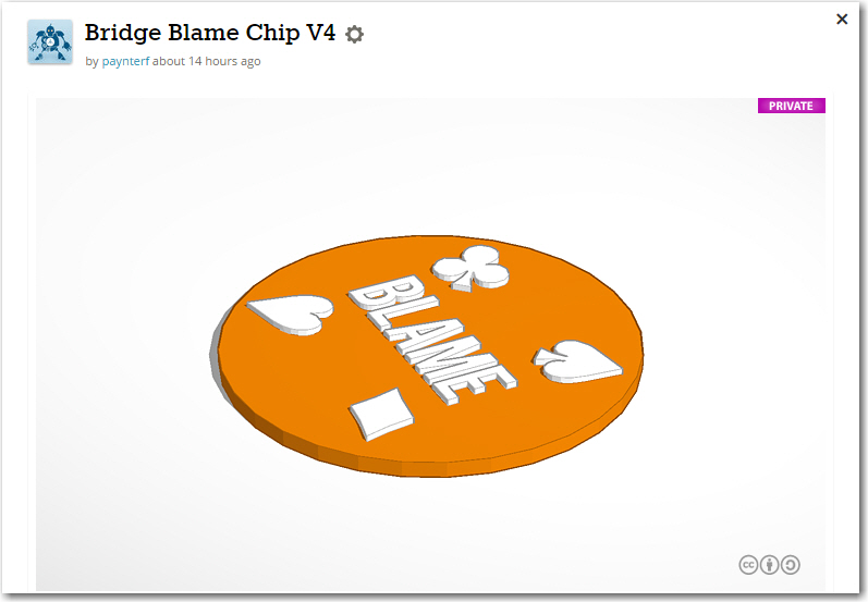
I started this project as I do almost all my new projects – researching on the internet with Google.  I found card and pip images, and then I found a set of zip files with 3D models of all the various card elements.  From this I extracted the 4 pips I needed (clubs, hearts, spades, diamonds), and arranged them circularly around the word ‘BLAME’, as shown in the following screenshot.

TinkerCad design for the Duplicate Bridge Blame Chip

TinkerCad design for the Duplicate Bridge Blame Chip

Then I printed it on my MicroCenter 3D Pro 3D printer, using blue and white (the two colors I had on the machine at the time).  Here are some photos of the result.

3D printed version of the 'Duplicate Bridge Blame Chip'.  The chip laying on the pen is actually two chips glued together to form a 2-sided chip.

3D printed version of the ‘Duplicate Bridge Blame Chip’. The chip laying on the pen is actually two chips glued together to form a 2-sided chip.

The items that come off the printer are blank on the reverse side, so to get a real 2-sided ‘poker chip’ style item, I simply printed two chips and glued them together.  In the photo above, the chip leaning on the pen is a 2-sided version, while the others are single-sided.

I’m not really sure where I’m going with this, as the sudden appearance of a real, physical ‘blame’ chip at the table may have unintended (read ‘disastrous’) consequences.  My wife has suggested these might make great bridge party favors, and I may try giving some of these away to established partnerships before I get too ambitious. Also, I will probably try printing some with white pips on a red background to see how they look.

Frank


LIDAR-Lite Gets its Own Motor

Posted June 16, 2015

In my last post (http://gfpbridge.com/2015/05/lidar-lite-rotates/ – over a month ago – wow!) I  described the successful attempt to mate  the Pulsed Lite LIDAR with  a 6-channel slip ring to form a spinning LIDAR system for my Wall-E wall-following robot.  As an expedient, I used one of Wall-E’s wheel motors as the drive for the spinning LIDAR system, but of course I can’t do that for the final system.  So, I dived back into Google and, after some research, came up with a really small but quite powerful geared DC motor rated for 100 RPM at 6 VDC (In the image below, keep in mind that the shaft is just 3mm in diameter!)
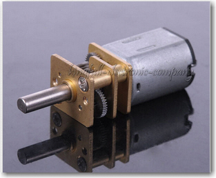
 

Very small 100RPM geared DC motor.  See http://www.ebay.com/itm/1Pcs-6V-100RPM-Micro-Torque-Gear-Box-Motor-New-/291368242712

Very small 100RPM geared DC motor. See http://www.ebay.com/itm/1Pcs-6V-100RPM-Micro-Torque-Gear-Box-Motor-New-/291368242712

In my previous work, I had worked out many of the conceptual challenges with the use of an offset motor, O-ring drive belt, and slip ring, so now the ‘only’ challenge was how to replace Wall-E’s  temporarily-borrowed wheel motor with this little gem, and then somehow integrate the whole thing onto the robot chassis.

The first thing I did was come up with a TinkerCad design for mounting the micro-motor on the robot chassis, and the pulley assembly from the previous study onto the motor shaft.  Wall-E’s wheel motor has a 6mm shaft, but the micro-motor’s shaft is only 3mm, so that was the first challenge.  Without thinking it through, I decided to  simply replace the center section of the previous pulley design with a center section sporting a 3mm ‘D’ hole.  This worked, but turned out to be inelegant and WAY too hard.  What I should have done is to print up a 3mm-to-6mm shaft adapter  and then simply use all the original gear – but no, I had to do it the hard way!  Instead of just adding  one new design (the 3mm-to-6mm adapter), I wound up redesigning both the pulley  and the tach wheel – numerous times because of course the first attempts at the 3mm ‘D’ hole were either too large or too small – UGGGGGHHHH!!

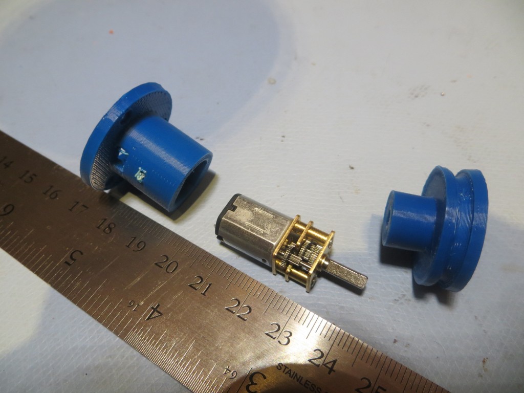
Anyway, the motor mount and re-engineered pulley/tach wheel eventually came to pass, as shown below.  I started with a basic design with just a ‘cup’ for the motor and a simple drive belt pulley.  Then I decided to get fancy and incorporate a tach wheel and tach sensor assembly into the design.  Rather than having a separate part for the sensor assembly, I decided to integrate the tach sensor assembly right into the motor mount/cup.  This seemed terribly clever, right up until the point when I realized there was no way to get the tach wheel onto the shaft and into the tach sensor slot – simultaneously :-(.  So, I had to redesign the motor ‘cup’ into a motor ‘sleeve’ so the motor could be slid out of the way, the tach wheel inserted into the tach sensor slot, and then the motor shaft inserted into the tach wheel ‘D’ hole – OOPS! ;-).
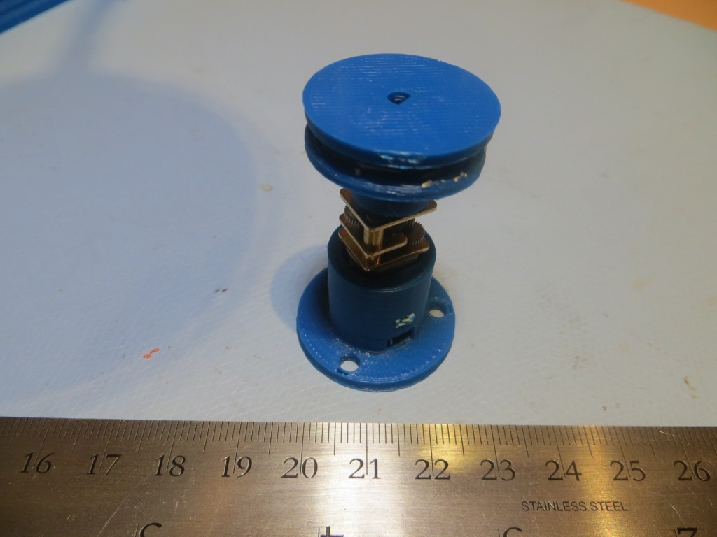
Assembled Miniature DC Motor Mount
Assembled Miniature DC Motor Mount

Miniature DC motor with chassis mount and belt drive wheel
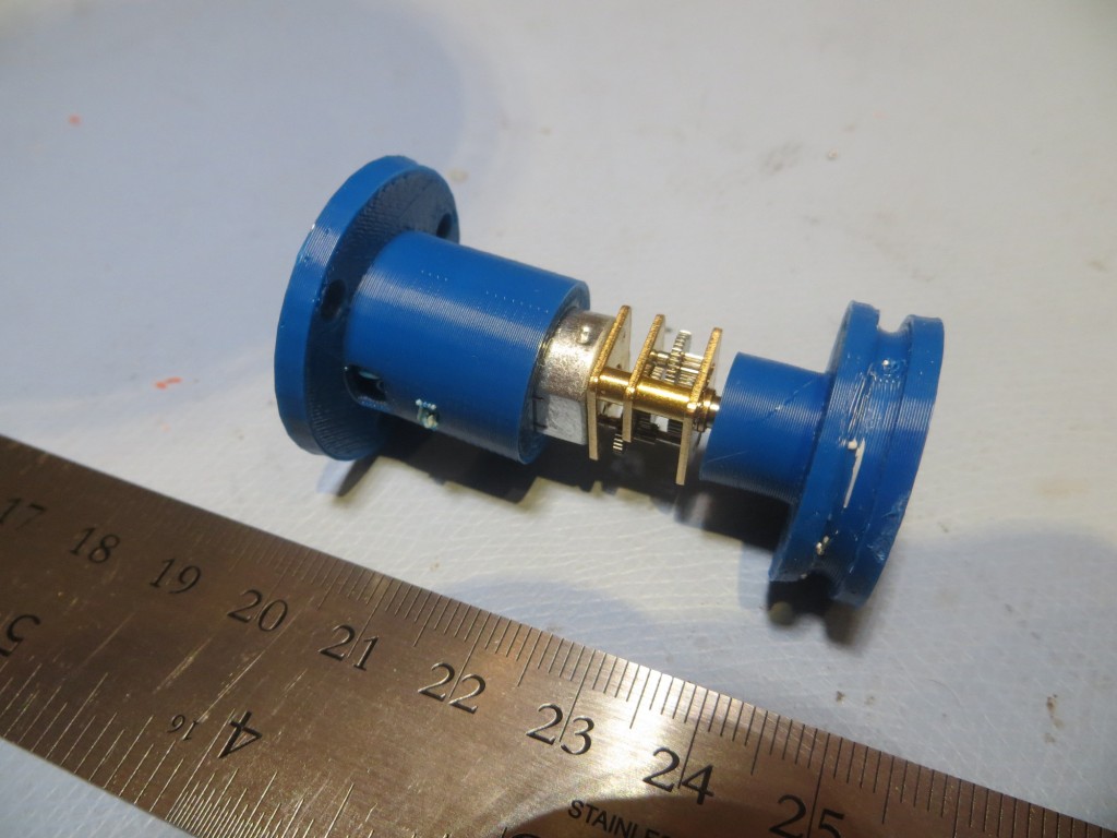
Miniature DC motor with chassis mount and belt drive wheel

Miniature DC motor partially installed in chassis mount
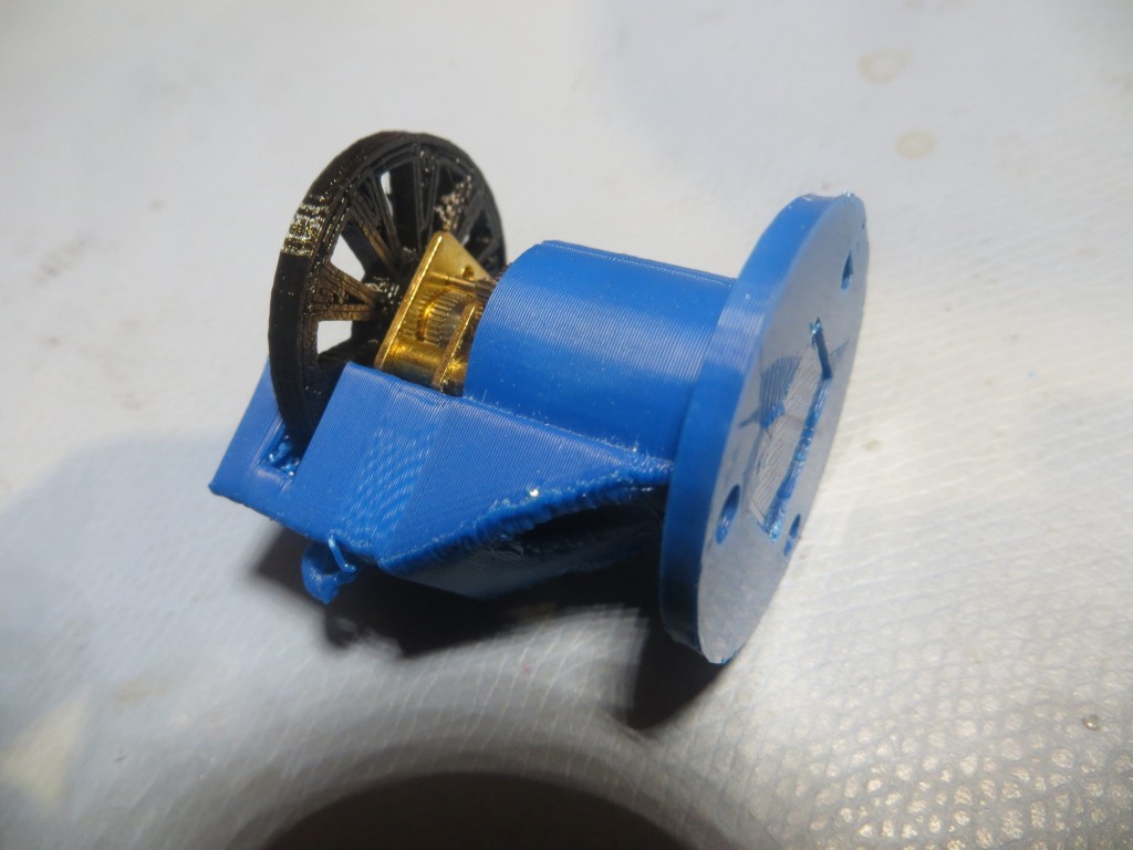
Miniature DC motor partially installed in chassis mount

MotorTachAssy1

Miniature DC motor mount, with tach sensor attachment, side/bottom view
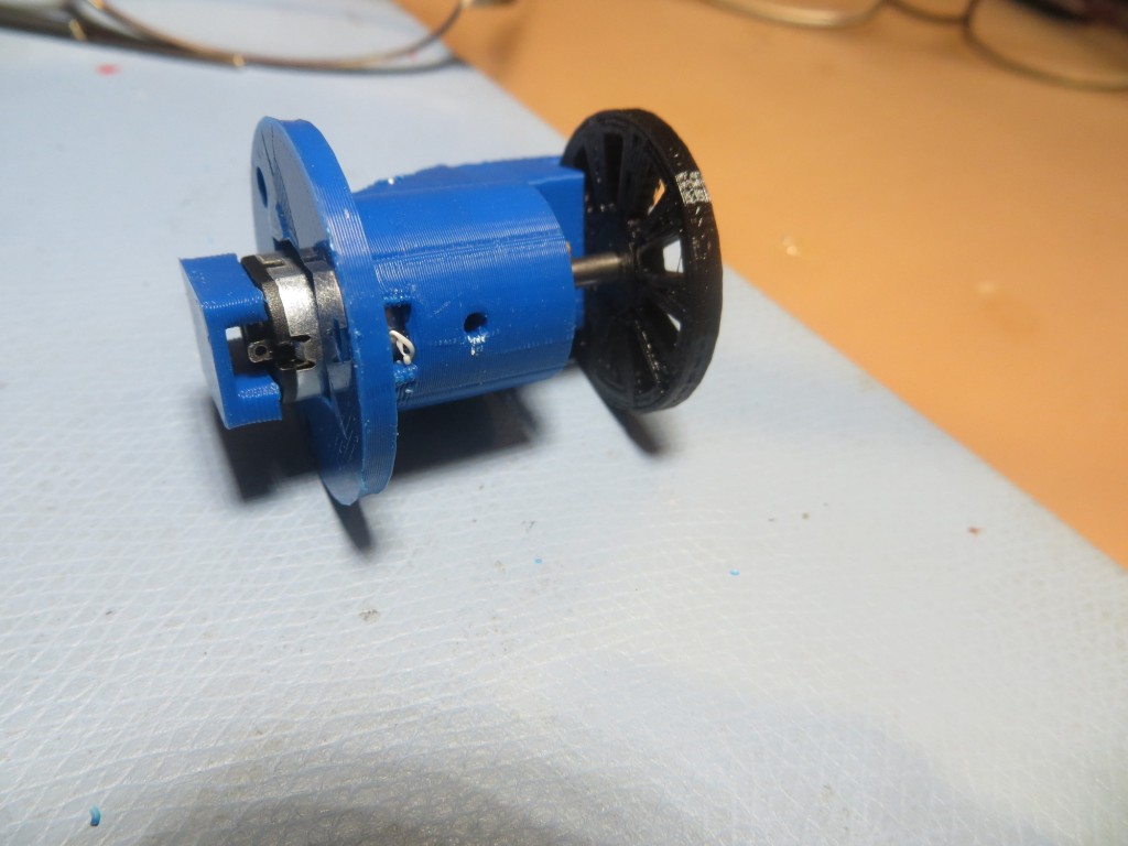
Miniature DC motor mount, with tach sensor attachment, side view showing motor contact cover
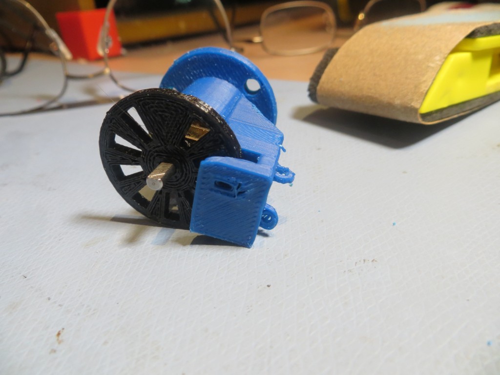
Miniature DC motor mount, with tach sensor attachment, side view showing motor contact cover

Miniature DC motor mount, with tach sensor attachment, top view
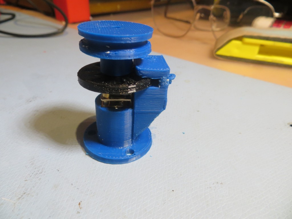
Miniature DC motor mount, with tach sensor attachment, top view

Completed assembly, with drive belt pulley and tach wheel

Next up – the LIDAR mount.  The idea was to mount the LIDAR on the ‘big’ side of the 6-channel slip ring assembly, and do something on the ‘small’ side to allow the whole thing to slide toward/away from the motor mount to adjust the drive belt tension.  As usual, I didn’t have a clue how to accomplish this, but the combination of TinkerCad and 3D printing allowed me to evolve a workable design over a series of trials.  The photo below shows the LIDAR mounted on the ‘big’ side of the slip ring, along with several steps in the evolution of the lower slide chassis mount
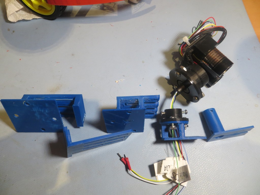
Evolution of the slide mount for the LIDAR slip ring assembly

Evolution of the slide mount for the LIDAR slip ring assembly

The last two evolutionary steps in this design are interesting in that I realized I could eliminate a lot of structure, almost all the mounting hardware, and provide much easier access to the screw that secures the slide mount to the robot chassis.  This is another  huge advantage to having a completely self-contained design-fabrication-test loop; a new idea can be designed, fabricated, and tested all in a matter of a half-hour or so!
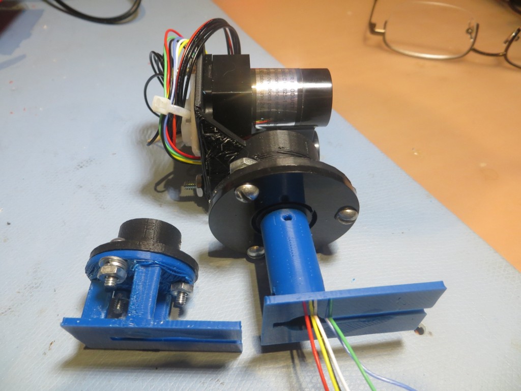
Original  and 2nd versions of the LIDAR slip ring assembly mount

Original and 2nd versions of the LIDAR slip ring assembly mount

Once I was satisfied that the miniature motor, the tach wheel and tach sensor assembly, and the spinning LIDAR mount were all usable, I assembled the entire system and tested it using an Arduino test sketch.


After a few tests, and some adjustments to the tach sensor setup, I felt I had a workable spinning LIDAR setup, and was optimistic that I would have Wall-E ‘back on the road again’ within a few days, proudly going where no robot had gone before.  However, I soon realized that a significant fly had appeared in the ointment – I wasn’t going to be able to accurately determine where the LIDAR was pointed – yikes!  The problem was this; in order to tell Wall-E which way to move, I had to be able to map the surroundings with the LIDAR.  In order to do that, I had to be able to associate a relative angle (i.e. 30 degrees to the right of Wall-E’s nose) with a distance measurement.  Getting the distance was easy – just ask the LIDAR for a distance measurement.  However, coming up with the relative angle was a problem, because all I really know is how fast the motor shaft is turning, and how long it has been since the index plug on the tach wheel was last ‘seen’.  Ordinarily this information would be sufficient to calculate a relative angle, but in this case it was complicated by the fact that the LIDAR turntable is rotating at a different rate than the motor, due to the difference in pulley diameters – the drive ratio.  For every 24mm diameter drive pulley rotation, the 26mm diameter LIDAR pulley only rotates 24/26 times, meaning that the LIDAR ‘falls behind’ more and more each rotation.  So, in order to determine the current LIDAR pointing angle, I would have to know not only how long it has been since the last index plug sighting, but also how many times the drive pulley has rotated since the start of the run,  and the exact relative positions of the drive pulley and the LIDAR at the start of the run.  Even worse, the effect of any calculation errors (inaccurate pulley ratio, roundoff errors, etc) is cumulative, to the point where after a few dozen revolutions the angle calculation could be wildly inaccurate.   And this all works  only if the drive belt has never slipped at all during the entire run.  Clearly this was  not going to work in my very non-ideal universe :-(.

After obsessing over this issue for several days and nights, I finally came to the realization that there was only one real solution to this problem.  The tach wheel and sensor had to be moved from the motor drive side of the drive belt to the LIDAR side.  With the tach wheel/sensor on the LIDAR side, all of the above problems immediately and completely disappear – calculation of the LIDAR pointing angle becomes a simple matter of measuring the time since the last index plug detection,  and calculation errors don’t accumulate.  Each time the index plug is detected, the LIDAR’s pointing angle is known  precisely; pointing angle calculation errors might  accumulate during each rotation, but all errors are zeroed out at the next index plug detection.  Moreover, the pointing angle calculation can be made arbitrarily accurate (to the limit of the Arduino’s computation capability and timer resolution) by using any per-revolution error term to adjust the time-to-angle conversion factor.  As a bonus, the motor no longer has to be speed-controlled – I can run it open-loop and just measure the RPM using the tach wheel/sensor.  As long as the motor speed doesn’t change significantly over multiple-revolution time scales, everything will still work.

So, back to TinkerCad for major design change number 1,246,0025 :-).  This time I decided to flip the 6-channel slip ring so the ‘big’ half  was on the chassis side, and the ‘small’ half was on the LIDAR side, thereby allowing more room for the new tach wheel on the spinning side, and allowing for a smaller pulley diameter (meaning the LIDAR will rotate faster for a given motor speed).  The result of the redesign is shown in the following photo.
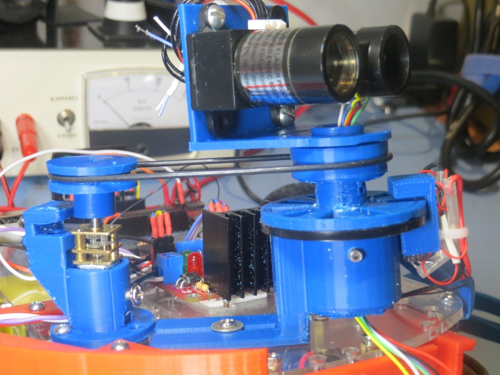
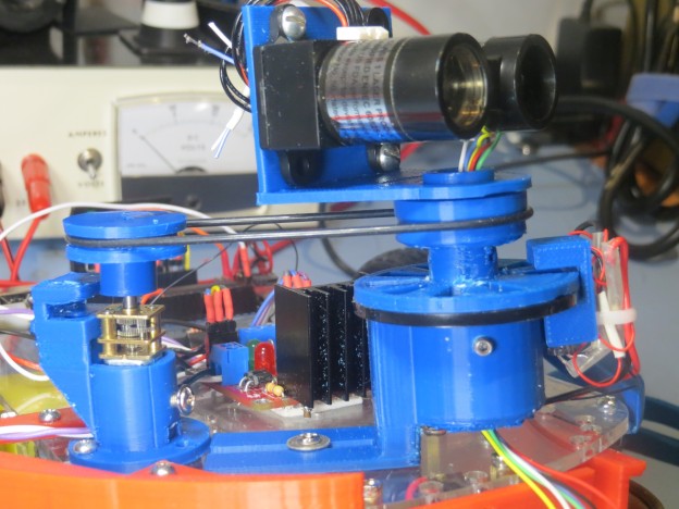
Revised LIDAR and DC motor mounting scheme, with Tach wheel and sensor moved to LIDAR mount

Revised LIDAR and DC motor mounting scheme, with Tach wheel and sensor moved to LIDAR mount

In the above photo, note the tach sensor assembly is still on the motor mount (didn’t see any good reason to remove it.  The ‘big’ (non-spinning) half of the slip ring module is mounted in a ‘cup’ and secured with two 6-32 set screws, and the tach wheel and LIDAR belt pulley is similarly mounted to the ‘small’ (spinning) half.  The tach sensor assembly is a separate peice that attaches to the non-spinning ‘cup’ via a slotted bracket (not shown in the photo).  The ‘big’  slip ring half is secured in the cup in such a way that one of the holes in the mounting flange (the black disk in the photo) lines up with the IR LED channel in the tach sensor assembly.  The tach wheel spins just above the flange, making and breaking the LED/photo-diode circuit.  Note also how the slip ring ‘cup’ was mounted on the ‘back’ side of the drive belt tension slide mount, allowing much better access to the slide mount friction screw.  The right-angle LIDAR bracket was printed separately from the rest of the LIDAR assembly to get a ‘cleaner’ print, and then press-fit onto the pulley/tach wheel assembly via an appropriately sized hole in the LIDAR bracket.    The following movie shows the whole thing in action


In the above movie, note the quality of the tach sensor signal; it is clamped to the voltage rails on both the upper and lower excursions, and the longer ‘high’ signal of the index plug is clearly visible at the far right of the oscilloscope screen.

Details of the Tach Wheel:

Wall-E’s spinning LIDAR system features a tachometer wheel with an ‘index plug’, as shown below.  Instead of a series of regularly spaced gaps, the gap in one section is missing, forming a triple-width ‘plug’ that allows me to detect the ‘index’ location.  However, this means that instead of 20 equally spaced open-to-opaque or opaque-to-open transitions, there are only 18, as two of the transitions are missing.  In addition, the LIDAR pointing angle isn’t as straightforward to calculate.  If the trailing edge of the ‘index plug’ is taken as 0 degrees, then the next transition takes place at 18 degrees, then 36, 54, 72, 90, … to 306  degrees.  However, after 306,  the next transition isn’t 324 degrees – it is 360 (or 0) as the 324  and 342 degree transitions (shown in red in the diagram below) are missing.  So, when assigning pointing angles to the interrupt number, I have to remember to multiply the interrupt index number (0 – 17) by 18 degrees (17*18 = 306).  This also means that there is no ability to ‘see’ obstacles in the 54 degree arc from 306 to 360 degrees.
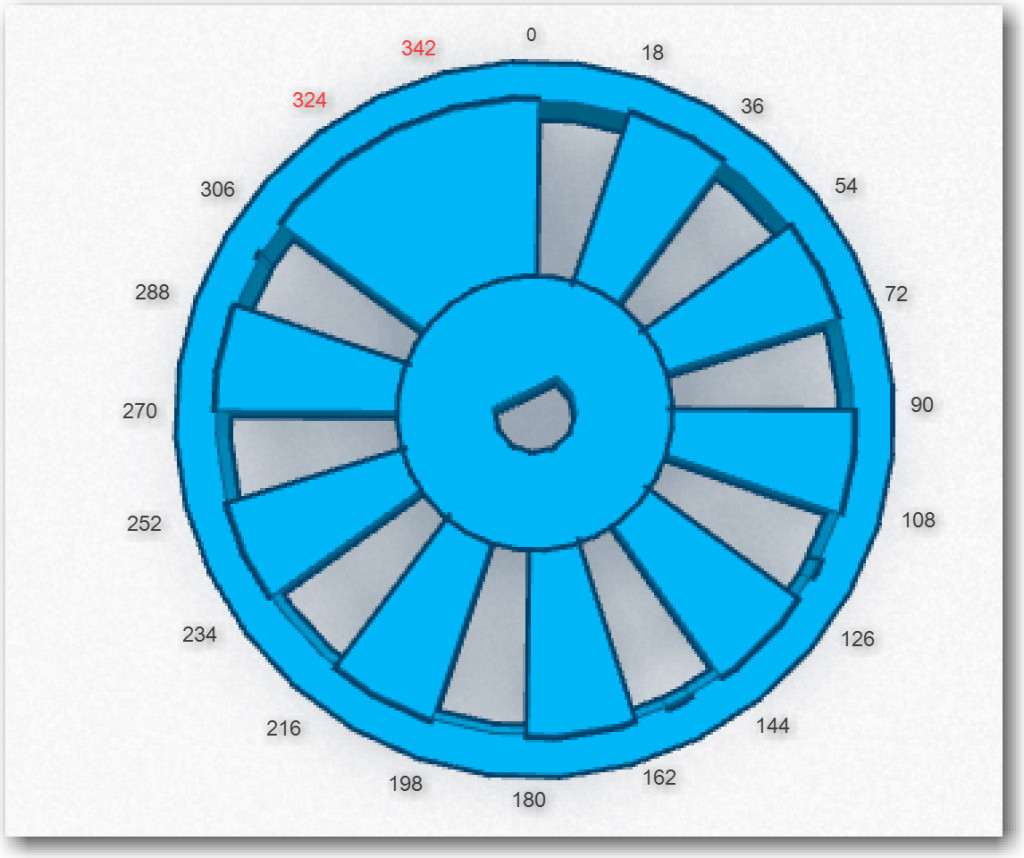
 

Diagram of the tach wheel for Wall-E's spinning LIDAR system

Diagram of the tach wheel for Wall-E’s spinning LIDAR system

Next Steps: Now that I have a LIDAR rotation system that works, the next step is to design, implement and test the program to acquire LIDAR distance data and accurately associate a distance measurement with a relative angle.  With the new tach wheel/sensor arrangement, this should be relatively straightforward – but how to test?  The LIDAR will be spinning at approximately 100 RPM, so it will be basically impossible to simply look at it and know where it is/was pointing when a particular measurement was taken, so how do I determine if the relative angle calculations are correct?

  • I could put the whole think in a large cardboard box like I did with the XV-11 NEATO spinning LIDAR system (see ‘Fun with the NEATO XV-11 LIDAR module‘);  If the (angle, distance) data pairs acquired  accurately depict the walls of the  container over multiple runs,  that would go a long way toward convincing myself that the system is working correctly.  I think that if the angle calculation was off, the lines plotted in one run wouldn’t line up with the ones from subsequent runs – in other words the walls of the box would blur or ‘creep’ as more data was acquired.  I could also modify the box with a near-distance feature at a known relative angle to Wall-E’s nose, so it would be easy to tell if the LIDAR’s depiction of the feature was in the right orientation.
  • I could mount a visible laser (similar to a  common AV pointer) to the LIDAR so I could see where it is pointing. This would be a bit problematic, because this would simply paint a circle on the walls of the room as the LIDAR spins.  In order to use a visible laser as a calibration device, I’d need  to ‘blink’  it on and off in synchronism with the angle calculation algorithm so I could tell if the algorithm was operating correctly.  For instance, if I calculated the required time delay (from the index plug detection time) for 0 degrees relative to the nose, and blinked the laser  at that time, I should see a  series of on/off dots directly in front of Wall-E’s nose.  If the dots appear at a different angle but are stationary, then I have a constant error term somewhere.  It they drift left or right, then I have a multiplicative factor error somewhere.

I think I’ll try both techniques; the box idea sounds good, but it may take a pretty large box to get good results (and I might even be better off using my entire office), and it might be difficult to really assess the accuracy of the system.  I already have a visible laser diode, so implementing the  second idea would only require mounting  the laser diode on top of the LIDAR and using two of the 6 slip ring channels to control it.   I have plenty of digital I/O lines available on the Arduino Uno, so that wouldn’t be a problem.
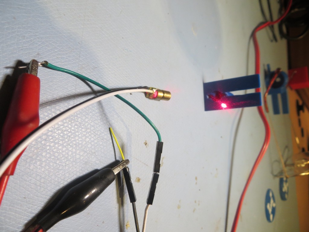
RobotGeek Laser, Item# ASM-RG-LASER available from Trossen Robotics (TrossenRobotics.com)

RobotGeek Laser, Item# ASM-RG-LASER available from Trossen Robotics (TrossenRobotics.com)

Stay tuned!


Frank



LIDAR-Lite Rotates!

Posted 5/29/15

In previous posts I described a couple of LIDAR alternatives to my original ultrasonic ping sensor system for Wall-E’s navigation capabilities, and the challenges I faced in implementing them.  The LIDAR-Lite module is easily interfaced to an Arduino controller via the I2C interface and there is  plenty of example code for doing this.  However, in order to use it as the primary navigation sensor, it needs to spin at a controlled 1-5 RPS (60-300 RPM) and there has to be a way to determine  the rotational  angle associated with each distance measurement.  In a previous post (http://gfpbridge.com/2015/05/dc-motor-speed-control-using-optical-tachometer/) I described my experiments with one of Wall-E’s wheel motors to implement speed control using an IR LED/photodiode/toothed-wheel tachometer.

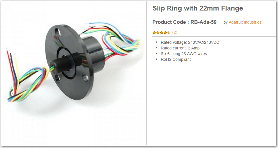
After successfully implementing speed control on Wall-E using the right wheel motor, I next turned my attention to implementing a drive train to connect the wheel motor to the LIDAR Lite unit.  I couldn’t just connect the LIDAR module to the motor shaft, as the LIDAR wiring would simply wrap itself to death as soon as the motor started turning.  I had previously acquired the  slip ring module  (described in  http://gfpbridge.com/2015/04/robot-of-the-future-lidar-and-4wd/) shown below

Adafruit Slip Ring with 6 contacts

Adafruit Slip Ring with 6 contacts

So I needed a way to connect the rotating part of the slip ring to the LIDAR module, and the non-rotating part to the robot chassis and (via a drive belt) to the motor shaft.

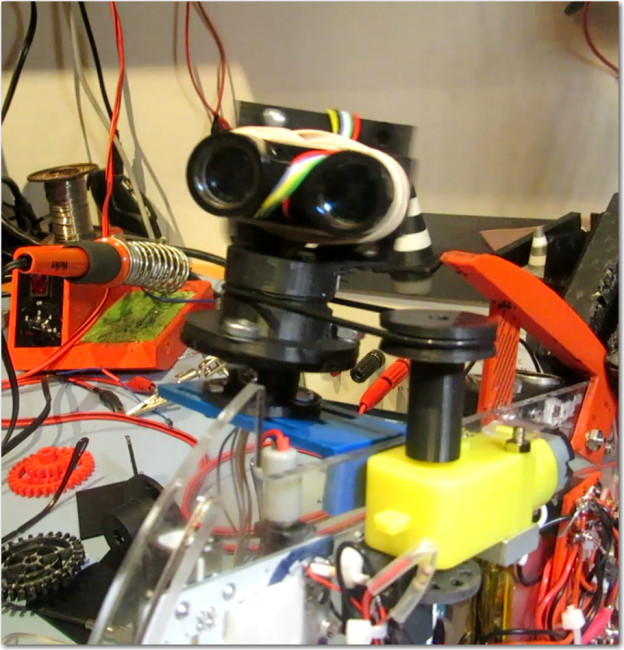
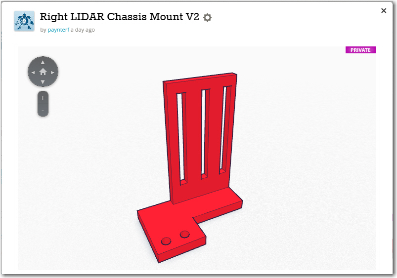
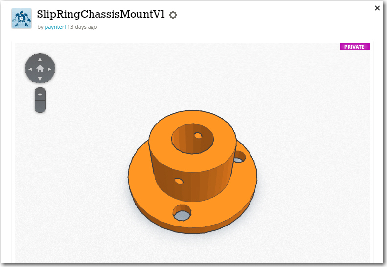
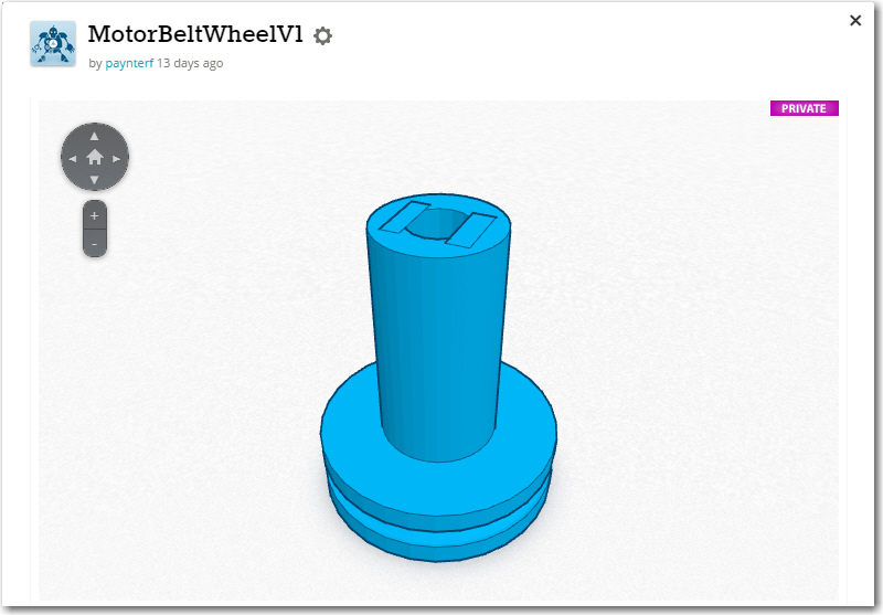
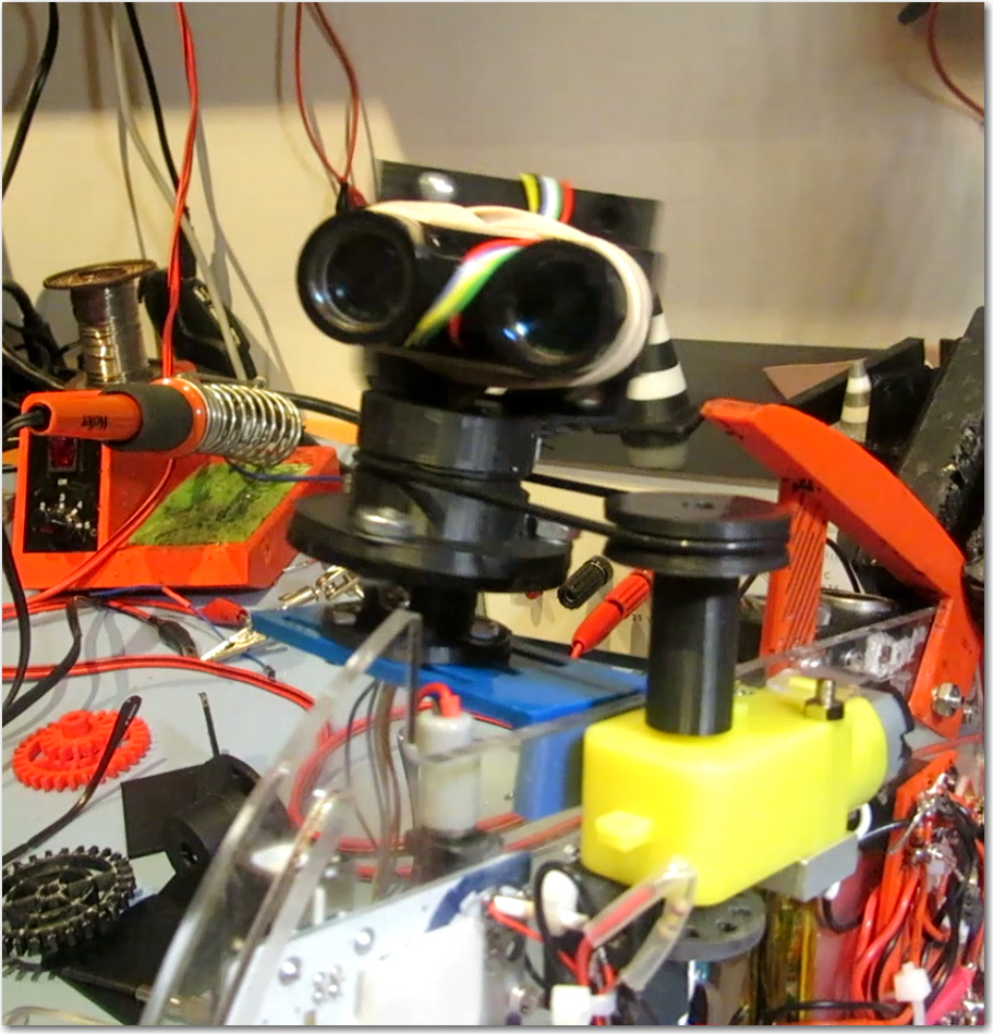
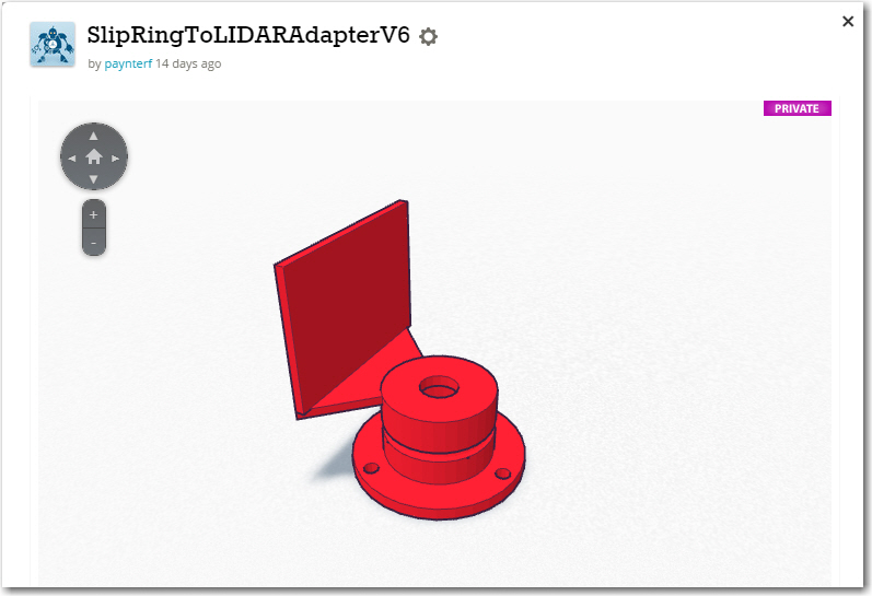
In TinkerCad, I designed a grooved pulley with a rectangular cross-section axial hole to fit over the motor shaft, an  adapter from the rectangular LIDAR mounting plate to the cylindrical slip ring rotating side, and a chassis mounting bracket that would allow the non-rotating side of the slip ring to be adjusted toward and away from the motor shaft pulley to properly tension the drive belt.  The drive belt is a standard rubber O-ring from McMaster Carr.

Now that I have motor speed control working and the LIDAR spinning, I need to connect the LIDAR electrically to the Arduino Uno controller and see if I can actually collect angle-specific LIDAR distance data (distance from the LIDAR, angle from the wheel speed tachometer control software).  Stay Tuned!

Frank


LIDARMountChassisBracket LIDARMountChassisSlipRing LIDARMountLIDARBracket LIDARMountMotorPulley

Spinning LIDAR drive assembly and LIDAR unit.  Note O-ring drive belt.

Spinning LIDAR drive assembly and LIDAR unit. Note O-ring drive belt.


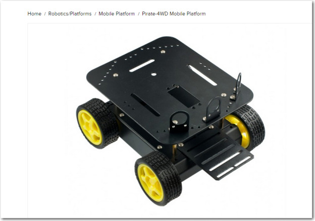
DFRobots ‘Pirate’ 4WD Robot Chassis

Posted 5/28/15

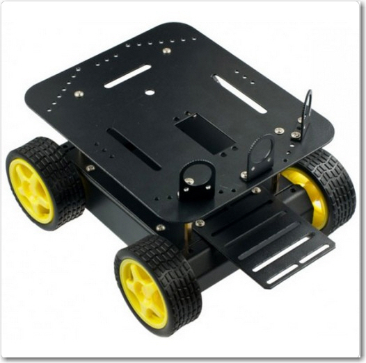
A while back I posted that I had purchased a new 4WD robot platform from DFRobot (http://www.dfrobot.com/), and it came in while I was away at a bridge tournament. So, yesterday I decided to put it together and see how it compared to my existing ‘Wall-E’ wall-following platform.

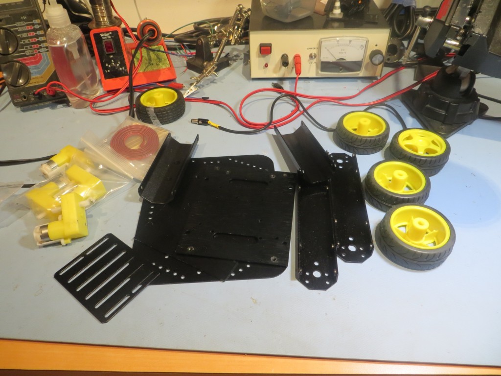
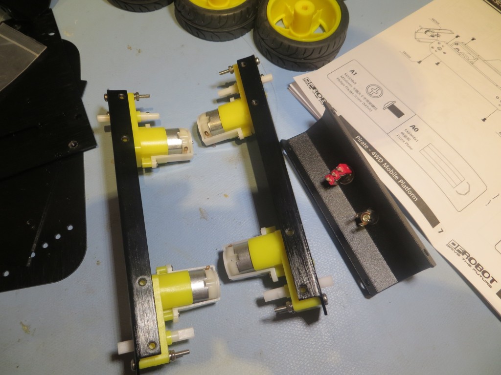
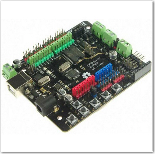
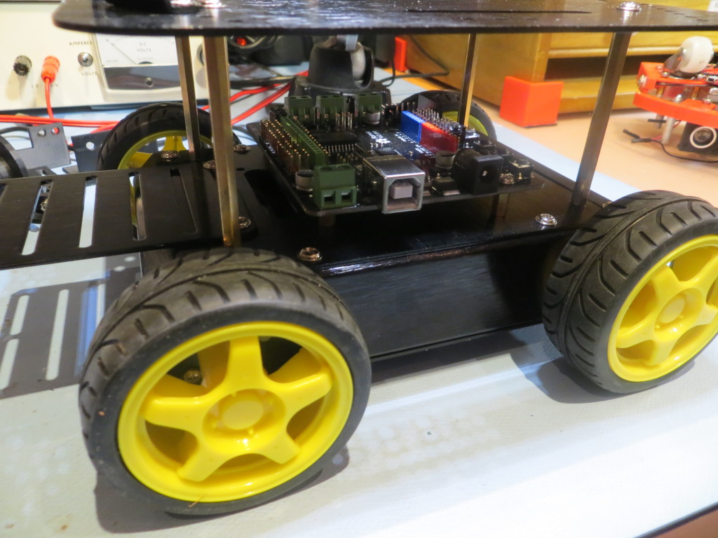
The chassis came in a nice cardboard box with everything arranged neatly, and LOTS of assembly hardware.  Fortunately, it also came with a decent instruction manual, although truthfully it wasn’t entirely necessary – there aren’t that many ways all the parts could be assembled ;-).  I had also purchased the companion ‘Romeo’ motor controller/system controller from DF Robot, and I’m glad I did.  Not only does the Romeo combine the features of an Arduino Leonardo with a motor controller capable of 4-wheel motor control, but the Pirate chassis came with pre-drilled holes for the Romeo and a set of 4 mounting stand-offs – Nice!

So, at this point I have the chassis assembled, but I haven’t quite figured out my next steps.  In order to use either the XV-11 or PulsedLight LIDAR units, I need to do some additional groundwork.  For the XV-11, I have to figure out how to communicate between the Teensy 2.0 processor and whatever upstream processor I’m using (Arduino Uno on Wall-E, or Arduino Leonardo/Romeo on the Pirate).  For the LIDAR-Lite unit, I have to complete the development of a speed-controlled motor drive for rotating the LIDAR.  Stay tuned!

Frank
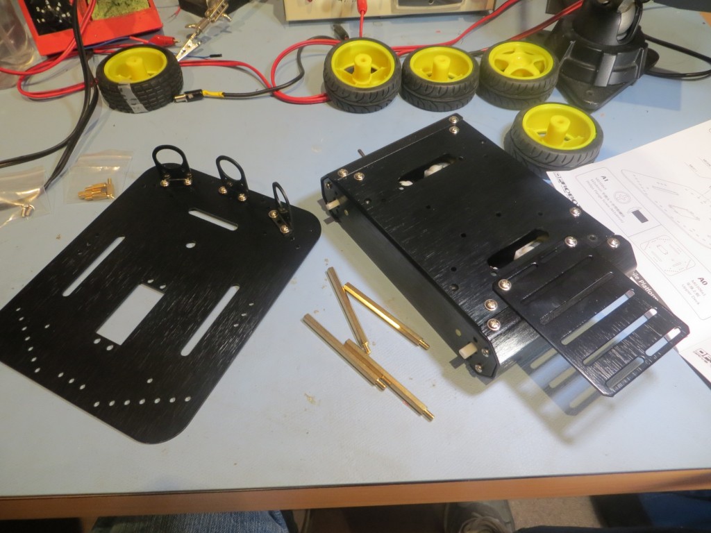
Parts, parts, and more parts!

Parts, parts, and more parts!

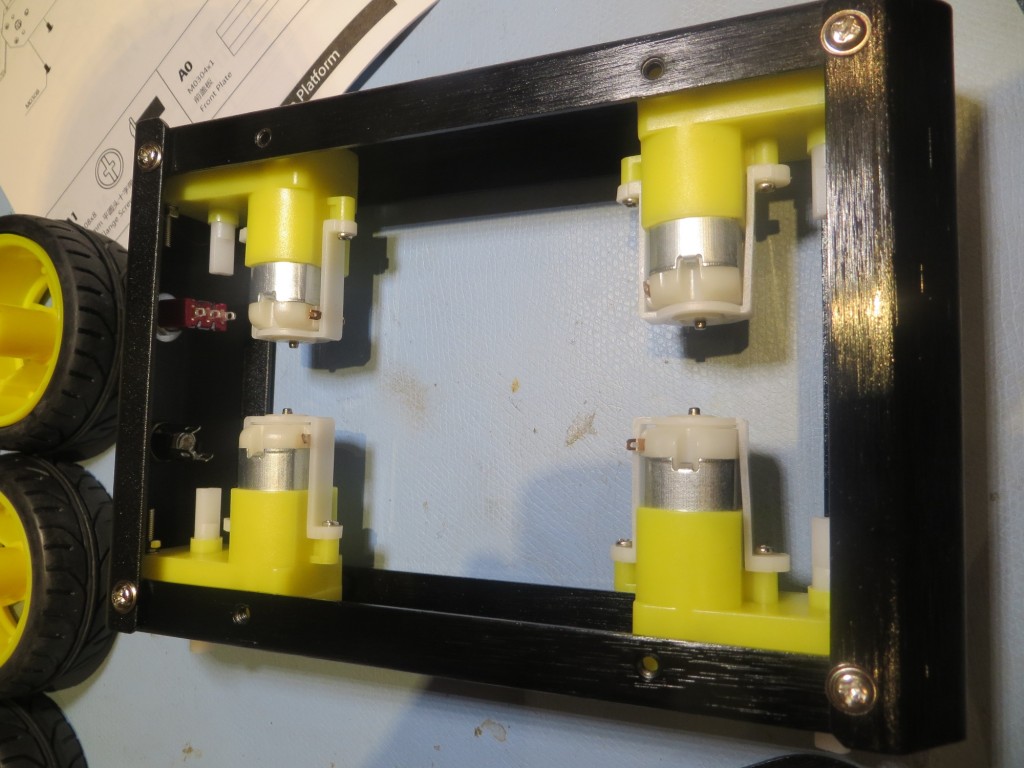
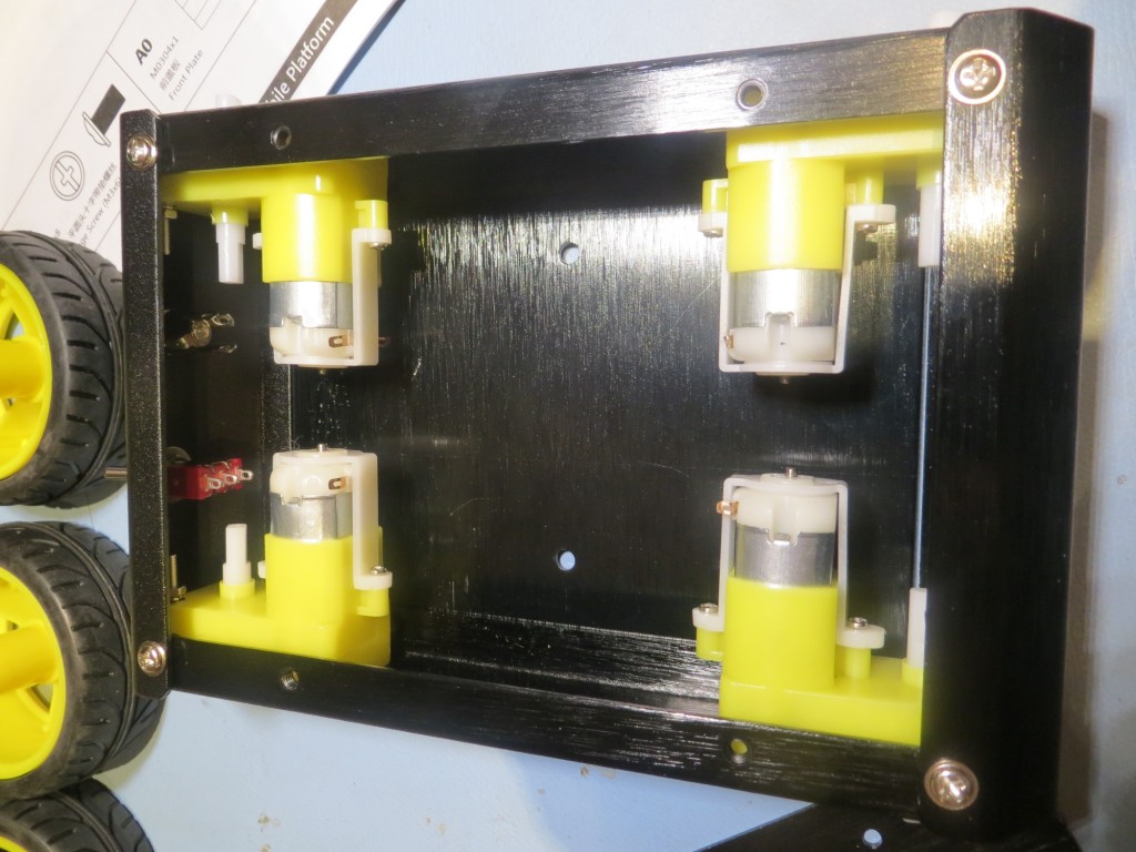
Motors installed in side plates

Motors installed in side plates

Side plates and front/back rails assembled

Side plates and front/back rails assembled

Bottom plate added

Bottom plate added

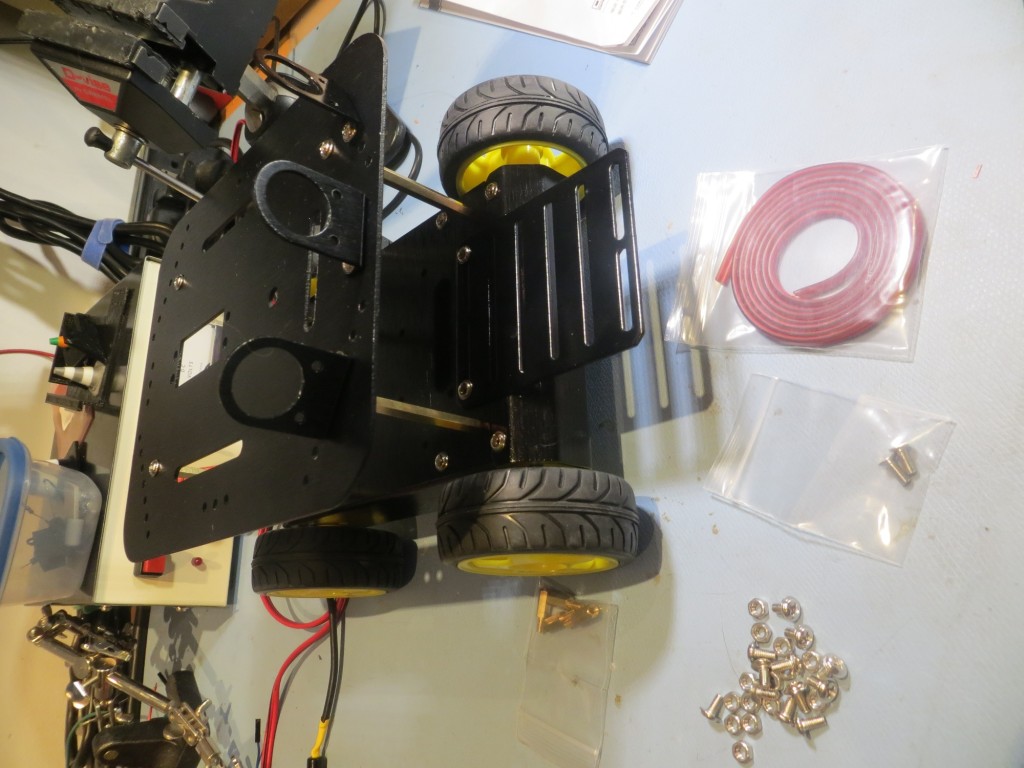
Getting ready to add the second deck

Getting ready to add the second deck

Assembled 'Pirate' chassis

Assembled ‘Pirate’ chassis

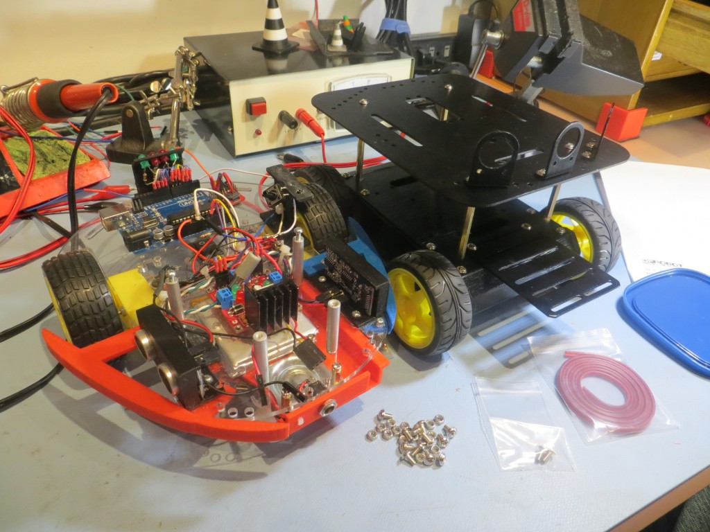
Side-by-side comparison of Wall-E platform with Pirate 4WD chassis

Side-by-side comparison of Wall-E platform with Pirate 4WD chassis

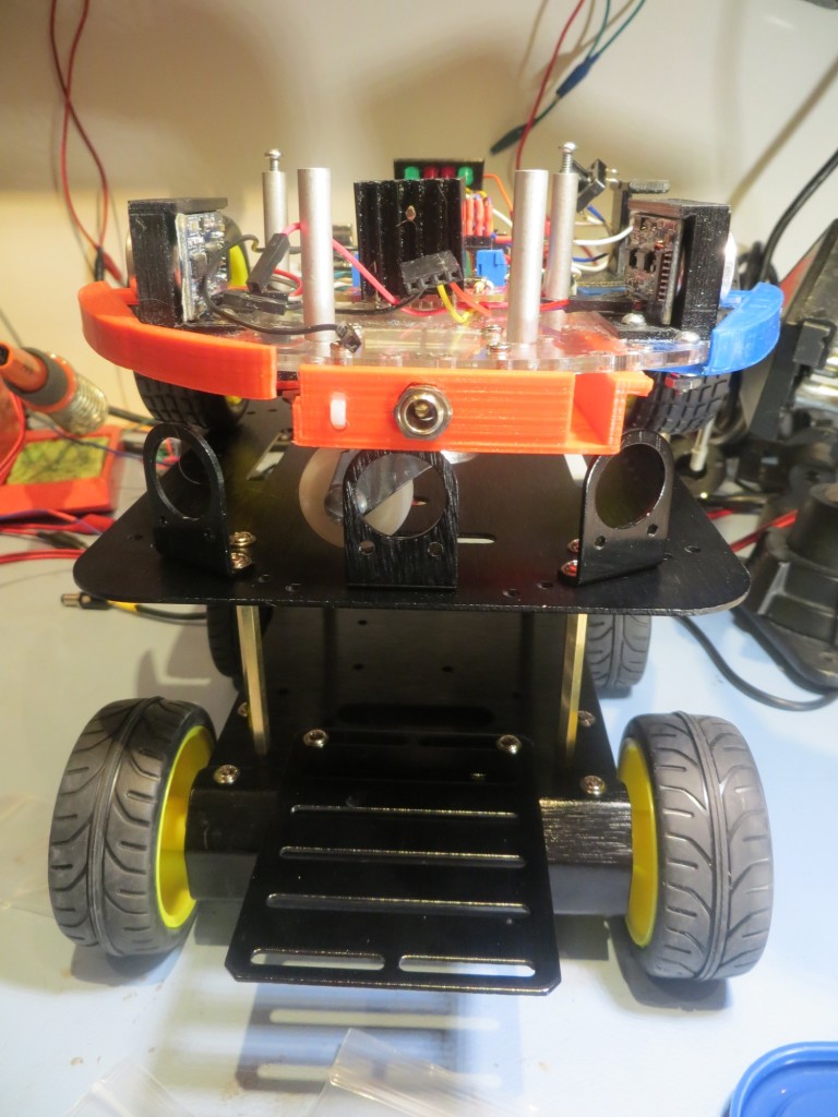
Over-and-under comparison of Wall-E platform with Pirate 4WD chassis

Over-and-under comparison of Wall-E platform with Pirate 4WD chassis

Optional 'Romeo' motor controller board.  Holes for this were pre-drilled in the Pirate chassis, and mounting stand-offs were provided - Nice!

Optional ‘Romeo’ motor controller board. Holes for this were pre-drilled in the Pirate chassis, and mounting stand-offs were provided – Nice!

Fun with the NEATO XV-11 LIDAR module

Posted 05/23/15

In my last post (DC motor speed control using optical tachometer) I described my effort to implement  a speed controller for one of Wall-E’s wheel motors so I could use it as the drive for  a spinning LIDAR  system using theLIDAR-Lite unit from  PulsedLIght (http://pulsedlight3d.com/products/lidar-lite).  Although I got the speed controller working, delivery of the 4WD robot chassis I had ordered to carry the LIDAR-Lite system was delayed so I couldn’t fully implement the system.  In the meantime, I decided to play with the NEATO LIDAR unit I had acquired from eBay.

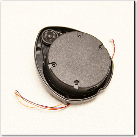
The NEATO XV-11 unit is a very cool self-contained spinning LIDAR unit intended for use in the NEATO robot vacuum cleaner.  I find it interesting and amusing that such a  technically elegant and useful module was developed for what is essentially a luxury toy, and  that it is available to hobbyists for a reasonable price!  The bad news is that the XV-11 emits a binary data stream that requires a fair bit of processing to make useful.  Fortunately for us mere mortals, Get Surreal (http://www.getsurreal.com/) produces a Teensy-based XV-11 controller (http://www.getsurreal.com/product/xv-lidar-controller-v1-2) that does most of the work; it has connectors to mate with the XV-11 on one end, and a USB connector on the other for data retrieval/control.  All that is required is an upstream USB  device with a serial monitor of some sort.  In my case, I used my laptop  and the RealTerm serial monitor (http://sourceforge.net/projects/realterm/) to do the job.

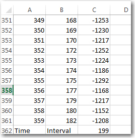
As an experiment, I placed the XV-11 in a 14 x 14 inch cardboard shipping box, and connected it up.  After capturing some processed data  using my laptop and RealTerm, I sucked the processed data into Excel 2013 for analysis.  The data transmitted by the Get Surreal Teensy controller is formatted as colon and space delimited (angle, distance, SNR) triplets.  Angle is in integer degrees, distance is in mm, and SNR  is an integer in parentheses with 0 representing missing data, and large numbers indicating high SNR.  At the end of each 360-degree set of data, the XV-11 reports the elapsed time (in integer millisec) for the previous data set.  The screenshot below shows the last few lines of a complete 360 degree dataset, along with the elapsed time value.

Last few items in a complete dataset, along with the elapsed time report

Last few items in a complete dataset, along with the elapsed time report

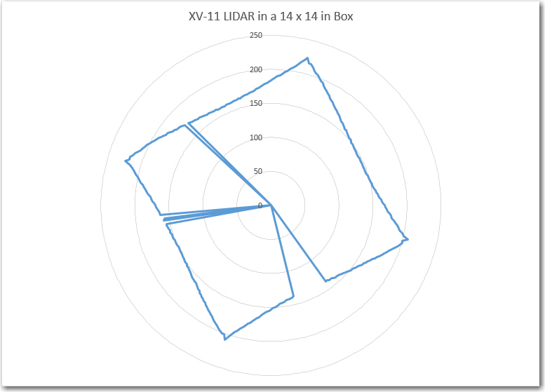
Excel – at least the 2013 version – is a very cool data analysis program.  Not quite as cool as MATLAB (which I used a  lot as a research scientist at Ohio State), but still pretty good, and nowhere near as expensive (it was free for me at the university, but it is very expensive for civilians).  Excel’s graphing routines are amazingly powerful and easy to use – much better IMHO than MATLAB’s.  In any case, I used Excel to graph some of the XV-11 data I had just captured.  I started with Excel’s stock polar graph (it’s called a Radar plot in Excel), and got the following plot with absolutely no effort on my part (other than selecting the Radar plot type)

Stock Excel Radar Plot for 360 degree data set.

Stock Excel Radar Plot for 360 degree data set.

This appears to be an excellent representation of the actual box, with a few data points missing (the missing points had SNR values of zero, so I could easily have gotten Excel to disregard them).  Although I had physically placed the XV-11 in the box in such a way as to be parallel with the sides of the box, the data shows a tilt.  This is due to the way that the XV-11 reports data – 0/360 degrees is  not the physical front of the device – it is offset internally by about 11 degrees (no idea why)

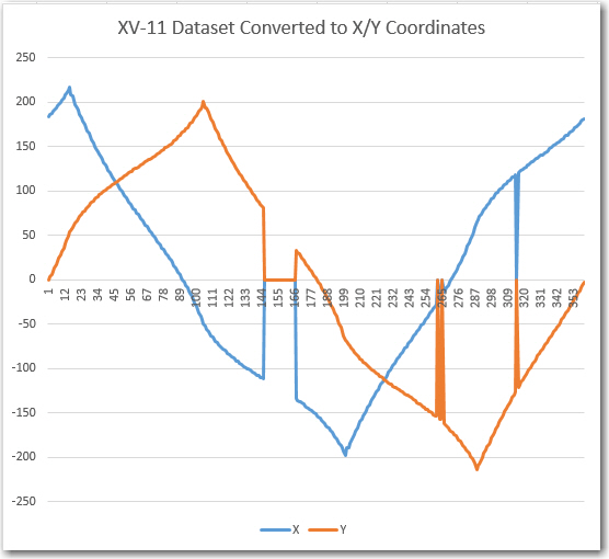
As my original Wall-E robot was conceived as a wall-following device, I was interested in using the LIDAR data to do the same thing – follow the walls.  So, I converted the polar (angle/radius) data into X/Y coordinates to see if I could condense the data down to something I could use for wall guidance.  The next plot is the same dataset as in the above plot, but converted to X/Y coordinates.

XV-11 Dataset converted to X/Y coordinate system

XV-11 Dataset converted to X/Y coordinate system

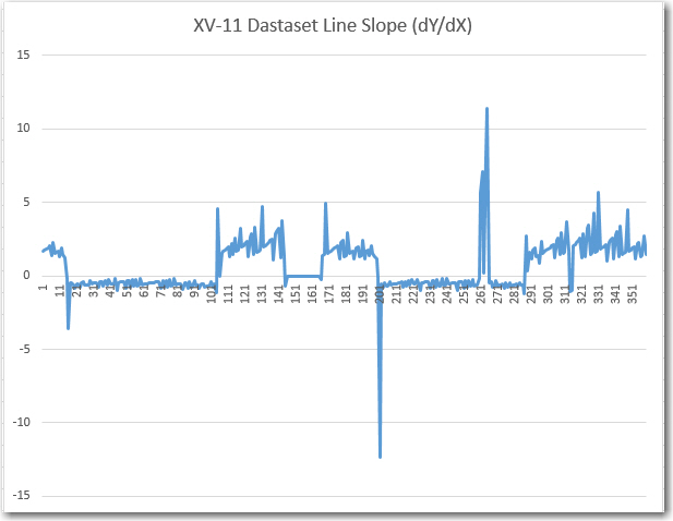
This, although perfectly understandable given the box environment, wasn’t really helpful as a possible wall-following algorithm, so I decided to look at the line slope instead of just the raw X/Y coordinates.  This gave me the next Excel plot, shown below.

Calculated line slope m = dY/dX for XV-11 dataset

Calculated line slope m = dY/dX for XV-11 dataset

This plot was interesting in that it definitely showed that there were only two slopes, and they were the negative reciprocals of each other, as would be expected from a box with two sets of parallel sides perpendicular to each other.   Also, having only two values to deal with vastly simplifies the task of making left/right steering decisions, so I thought maybe I was on to something for LIDAR Wall-E.

As I drifted off to sleep that night, I was reviewing my results so far when it occurred to me that I was thinking of the problem the wrong way – or maybe I was trying to solve the wrong problem.  I was trying to use LIDAR data to follow walls a la Wall-E, but what I really wanted to do was have the robot navigate typical indoor layouts without getting stuck anywhere. I had chosen a wall-following algorithm because that’s what I could do with ultrasonic ping sensors.  Another possible way to solve the  problem is to have the robot move  in the direction  that offers the  least restriction; i.e. in the ‘most open’ direction.  This would be very difficult to accomplish with ping sensors due to their limited range and inherent multipath and fratricide problems.  However, with a LIDAR that can scan the entire 360 degrees in 200 msec, this becomes not only possible, but easy/trivial.  So, the new plan is to mount the XV-11 LIDAR on Wall-E, and implement the ‘most open in the forward direction’ algorithm.  This  should result in something very like wall-following in a long hallway, where the most open forward direction would be along the length of the hall.  When the robot gets near the end of the hall, then either the left or right perpendicular distance will become ‘the most open’ direction which should cause Wall-E to make a hard right or left turn, followed by another same-direction turn when it gets close to the other wall. After the two right-angle turns, Wall-E should be heading back down the hall in the opposite direction.

Stay tuned…

Frank
 

DC motor speed control using optical tachometer

Posted 04/13/15

In my last post I described my plans for upgrading Wall-E (my Wall-following Robot) with a LIDAR package of some type, and my thought that I might be able to use such a package to not only replace the existing front-facing ping sensors, but (with a bit of rotating magic) the side sensors as well.

In order to replace *all* the sensors, the LIDAR package would have to rotate fast enough so that it could produce front, left, and right-side distance readings in a timely enough fashion to actually implement wall-following.  I’m not sure exactly what the requirements for wall-following are, but I think it’s safe to say that at least the measurements to the followed wall must be in the several-per-second range, or Wall-E could run into the wall before it figures out it is getting too close.  The other side, and the front could be taken at a more relaxed pace if necessary, but the wall being tracked has to be done correctly.

In order to rotate a unit such as the LIDAR-Lite from PulsedLight, I would  need a speed-controlled motor of some kind.  I considered  both stepper motors and direct-drive DC motors.  Since I already had two DC motors (the left and right wheel motors on Wall-E) and they came with ‘tachometer sensors’ (plastic disks with slots for optical wheel motion sensing), I thought I’d give this a try.  Earlier in my robot startup phase, I had obtained  some IR LED/Photodiode pairs, so I had at least the basic building blocks for a tachometer system.  I was  already speed-controlling Wall-E’s wheel  motors for steering using PWM from the Arduino Uno, so that part was already in place.  ‘All’ I had to do was couple the input from a tachometer into the already-existing PWM speed control facility and I would have a closed-loop speed-controlled rotating base for my LIDAR system – cool!

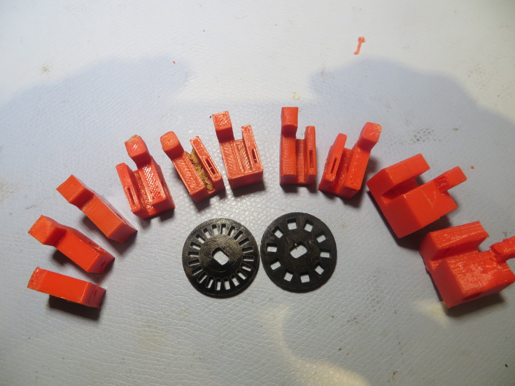
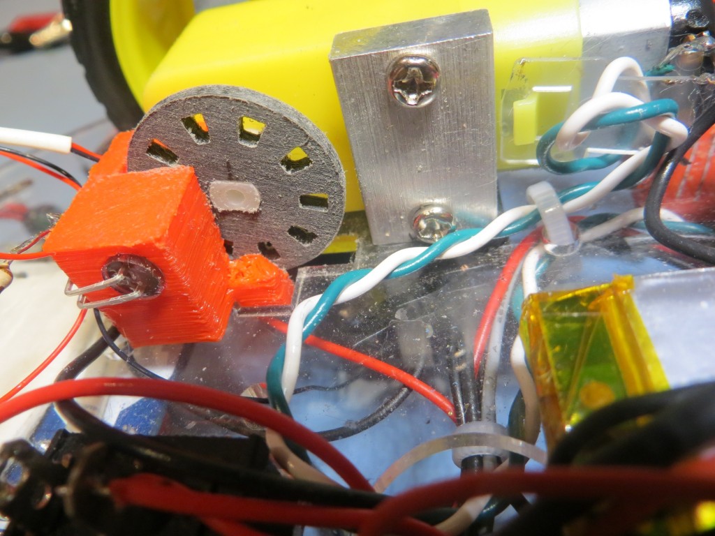
OK, so now I have all the parts for a speed-controlled motor system – I just have to assemble them. First up was a way of mounting the IR LED and IR detector in such a way that the slots in the tachometer wheel would alternately make and break the light path between them.  In the past when I had to do something like this, I would carve or glue something out of wood, or bend up some small pieces of aluminum.  However now I have a very nice 3D printer and the TinkerCad design package, so I could afford to do this a different way.  The confluence  of hobby robotics and 3D printing allows so much more design/development freedom that it almost takes my breath away.  Instead of dicking around for a while and winding up with something half-assed that is used anyway because it is way too much trouble to make another  -better – one, a 3D printer based ‘rapid iteration’ approach allows a design to  be evolved very quickly, with each iteration so cheap as to be literally throw-away.    To illustrate the approach, the image below shows the evolution of my IR LED/IR detector bracket, along with the original 20-slot tachometer wheel that came with the motors and a 10-slot version I printed up as a replacement (the tach signal-to-noise ratio was too low with the 20-slot original).

Evolution of an IR tach sensor bracket, along with the original and a custom-printed tach wheel

Evolution of an IR tach sensor bracket, along with the original and a custom-printed tach wheel

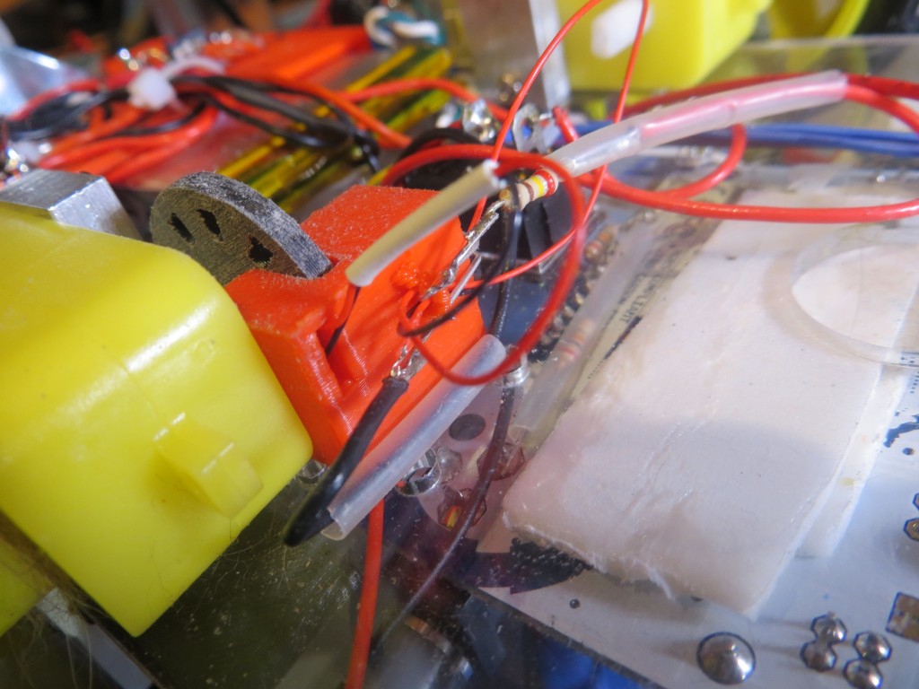
The evolution proceeded from left to right in the image.  I started with just a rectangular piece with a horizontal hole to accommodate the IR LED, and a threaded hole in the bottom to affix it to the robot chassis.  Then the design evolved a ‘foot’ to take advantage of a convenient slot in the robot chassis, for physical stability/registration purposes.  Then I added a second side with a slot in it to accommodate the  IR detector, with the tach wheel passing between the two sides.  This basic two-sided design persisted throughout the rest of the evolution, with additional material added on the IR LED side to accommodate the entire length of the IR LED.  Not shown in the photo are some internal evolutionary changes, most notably the width of the slot that allows IR energy from the LED to fall on the detector – it turns out that the detector opening should be about 1/2 the width of a tooth slot for best signal.  Each step in the above evolution cost me about 30 minutes of design time in TinkerCad, and a few pennies worth of filament.  Moreover, once I have the end design, printing more is essentially free.  Is that cool, or what?

Wall-E's right motor being used as my tachometer test bed

Wall-E’s right motor being used as my tachometer test bed.  Note the piece of scotch tape on the wheel, used for manually timing RPM.

Tachometer sensor bracket, showing IR LED and tach wheel

Tachometer sensor bracket, showing IR LED and tach wheel

Tachometer sensor bracket, showing slot for the IR detector

Tachometer sensor bracket, showing slot for the IR detector

Since I was already controlling the speed of Wall-E’s motors with an Arduino Uno (albeit for steering), I simply modified the wall-following program to act as a test driver for the tach feedback system.  The output of the IR detector was connected to an analog input, and the analog readings were captured and imported into an Excel spreadsheet for analysis.

The first test showed that I wasn’t getting enough signal swing between the slot and non-slot (plug) states of the tach wheel (less than 100 out of a possible 1024 levels), and this led me to start experimenting with different IR detector apertures.  As shown in the second plot below, constricting the aperture provided a marked improvement in SNR (about 3 times the peak-peak variation).

First test of the tach sensor system.  Note the not-impressive variation between wheel slot and plug readings

First test of the tach sensor system. Note the not-impressive variation between wheel slot and plug readings

Paper barrier with a small slot placed in front of detector aperture

Paper barrier with a small slot placed in front of detector aperture

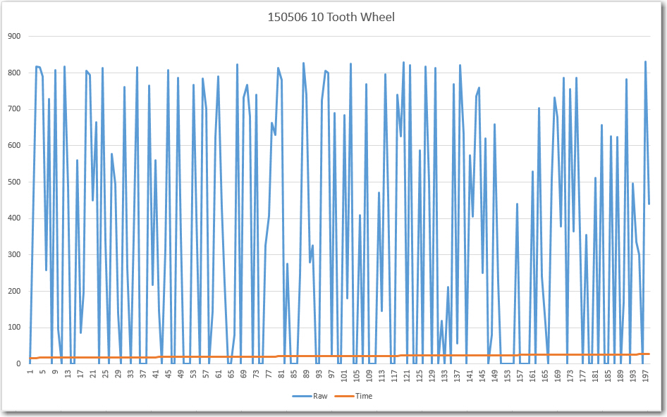
The above results led directly to the final round of evolutionary changes to the tach sensor bracket, where the detector aperture was changed from a large circle (same diameter as the IR LED) to a small slit.  In addition, to further improve the SNR, the tach wheel itself was redesigned from 20 slots to 10  with  the slots and plugs equal area.  In addition one slot was removed to create an absolute wheel position ‘index mark’.  After these changes, the tach sensor test was redone resulting in the following plot.

IR Detector response with a narrow slit aperture and a 10-tooth wheel.

IR Detector response with a narrow slit aperture and a 10-tooth wheel.

Now the signal varies from 0 to 800, allowing easy and reliable ‘off’ to ‘on’ state detection, and index mark detection.

After incorporating the physical changes noted above, an Arduino program was developed to test whether or not the motor could be accurately speed controlled.  Rather than trying to manually threshold-detect the above waveform, I simply used  Mike Schwager’s very cool EnableInterrupt Library (see  https://github.com/GreyGnome/EnableInterrupt) and set the Tach signal analog input to trigger an interrupt on each signal change.  This resulted in two interrupts per slot position, but this was easily handled in the software.

After getting the program working,  I found that I could control the motor such that, when set to 60 rpm, 20 wheel revolutions (as measured by counting the scotch tape on the wheel) took exactly 20 seconds.

Well, I’m not quite sure where I’m going from here.  Now I have demonstrated that I can control a typical hobbyist/robot motor for use as a LIDAR turret.  However, I’m not entirely convinced that a spinning LIDAR can produce wall distance measurements fast enough for successful wall following, and it will be a major PITA to modify Wall-E sufficiently to find out.  For one thing, I can’t really use one of Wall-E’s drive wheels as the LIDAR turret motor without giving Wall-E an unacceptable ‘limp’  (If I did that, I guess I would have to change his name from ‘Wall-E’ to ‘Quasimodo’ ;-)).  For another, to mount the LIDAR and turret on the current Wall-E chassis would be a major project by itself, as Wall-E’s real estate is already heavily populated with ‘stuff’.

So,  I think I’m going to wait until my new 4WD robot chassis arrives (it was unfortunately delayed for a week or so), and then build it up from scratch as a LIDAR-only platform. I can then use one of the motors from Wall-E as the turret motor for the PulsedLight LIDAR-Lite system.  In the meantime, I think I’ll try and mount the NEATO XV-11 spinning LIDAR on Wall-E, as it doesn’t require any additional motors (it has its own motor built in), and see if I can successfully follow a wall using only LIDAR.

Stay Tuned…


Frank


Robot of the future – LIDAR and 4WD

Posted 04/29/15

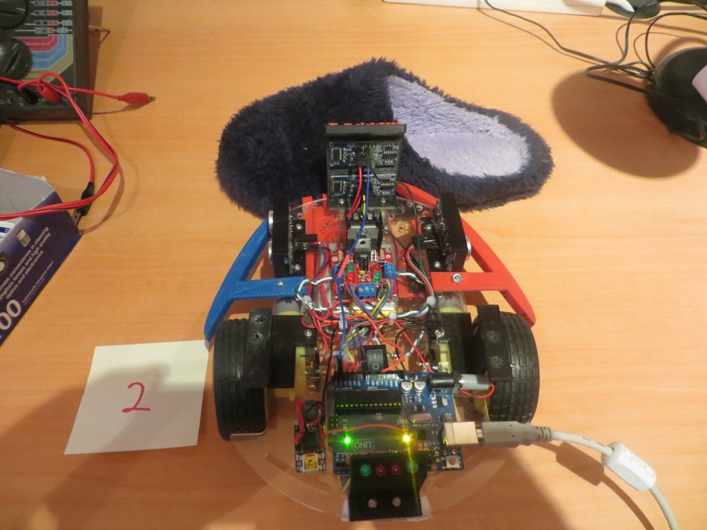
In a whole series of posts over this last month, I described the results of my efforts to solve the ‘stealth slipper’ problem, where Wall-E gets stuck on my wife’s fuzzy blue slippers and can’t seem to reliably detect this condition.  I ran a large number of experiments which eventually convinced me that the ultrasonic sensors I have been using for wall-following  and ‘stuck’ detection just aren’t up to the task. Even the use of  two forward-looking ping sensors, which I thought was going to be a really cool and elegant solution, didn’t do the job.  There is just too much data corruption due to multipath and ‘friendly fire’ corruption between ping sensors to reliably discriminate the ‘stuck on stealth slippers’ condition.

Slipper turned 90 degrees  clockwise

Slipper turned 90 degrees clockwise

So, its time to consider other, more radical, alternatives.  First and foremost, it is clear that ultrasonic sensing will not work for ‘stealth slipper’ detection/avoidance.  Other possible sensing modes are:

  • IR Ranging:  This has the advantage of being pretty cheap, but hobbyist IR ranging options like the Sharp IR Range Sensor (shown below) are fairly short range, slow, and have just an analog output with limited accuracy.

    Sharp IR Range Sensor

    Sharp IR Range Sensor

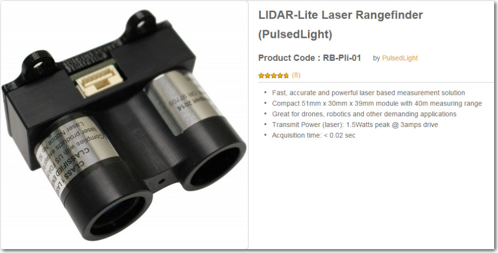
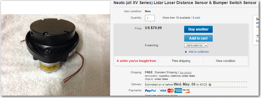
  • LIDAR:  This technology is fast, can be very long range, and can provide very accurate ranging information.  Unfortunately these sensors tend to be heavier and much more expensive than either the ultrasonic or IR sensor options.  The CentEye/ArduEye laser range finder using the Stonyman vision chip was a really cool, light weight and cheap solution, but it is unfortunately out of production and unavailable :-(.  The best of the lot for now appears to be the LIDAR-LITE sensor or the fully-assembled LIDAR package that is part of the NEATO robot vacuum cleaner.
    PulsedLight LIDAR-Lite unit

    PulsedLight LIDAR-Lite unit

    Neato Robotic Vacuum LIDAR module

    Neato Robotic Vacuum LIDAR module

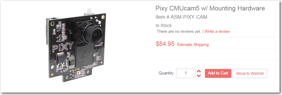
  • Optical parallax vision processing:  This is really the same as the LIDAR option, but with separate  laser, receiver, and parallax computation modules.  This is what the now-unobtainable Stonyman chip/Laser/Arduino solution did, but there are other, less attractive, ways to do the same thing.  One is a combination of a cheap laser diode and the Pixy CMU Cam.  The Pixy module handles a lot of the vision pre-processing necessary for parallax range determination, and the laser diode would provide the bright, distinct spot for it to track.Pixy CMU Cam module

After looking through the available options, it occurred to me that something like the LIDAR-Lite might allow me to  not only replace the forward-looking sensor on WallE, but maybe even the side ones as well.  The LIDAR-Lite is fast enough (20 msec/reading) that I should be able to use it for all three directions (left, right, forward).  In fact, if I mounted it on a servo motor using something like the Adafruit slip ring component shown here, I could implement a cool 360-degree LIDAR

Adafruit Slip Ring with 6 contacts

Adafruit Slip Ring with 6 contacts

It also occurred to me that while I’m in the process of making radical changes to WallE’s sensor suite, I might want to consider changing WallE’s entire chassis (I think this is the robot equivalent of ‘repairing’ a car by lifting up the radiator cap and driving a new car under it).  The 2-wheel plus castering nose wheel arrangement with the current WallE leaves a lot to be desired when navigating around our house.  Too often the castering nose wheel gets stuck at  the transition from the kitchen floor to the hall carpet or the area rugs.  In addition the nose wheel axle/sleeve space tends to collect dirt and cat hair, leading to the castering nose wheel acting more like a castering nose skid than a wheel ;-).  After some more quality time with Google, I came up with a very nice 4-wheel drive DFRobot 4WD Arduino Mobile Platform  robot chassis from DF Robots, along with the companion ‘All In One Controller‘.

DFRobot 4WD Arduino Mobile Platform

DFRobot 4WD Arduino Mobile Platform

DFRobot Romeo V1 All-in-one Microcontroller (ATMega 328)

DFRobot Romeo V1 All-in-one Microcontroller (ATMega 328)

Adventures with Wall-E’s EEPROM, Part VI

Posted 04/26/15

In my last post I showed there was a  lot of variation in the data from Wall-E’s  ping sensors – a lot more than I thought there should be.  It was apparent from this run that my hopes for ‘stuck’ detection using variation (or lack there of) of distance readings from one or more sensors were futile – it just wasn’t going to work.

At the end of the last post, I postulated that maybe, just maybe, I was causing some of these problems by restricting the front sensor max distance to 250 cm.  It was possible (so I thought) that opening up the max distance to 400 cm might clean up the data and make it usable.  I also hatched a theory that maybe motor or movement-related vibration was screwing up the sensor data somehow, so I ran some tests designed to investigate that possibility as well.

So, I revised Wall-E’s code to bump the front sensor max distances to 400 cm and made a couple of runs in my test hallway (where the evil stealth slippers like to lurk), to test this idea.  The code adjustment had a bit of a ripple effect, because up til now I had been storing the distance data as single bytes (so could store a distance reading of 0-255 cm), and storing 2-byte ints was going to take some changes.  Fortunately a recently released update to the EEPROM library provide the put() and get() methods for just this purpose, so I was able to make the changes without a whole lot of trouble.

Results:

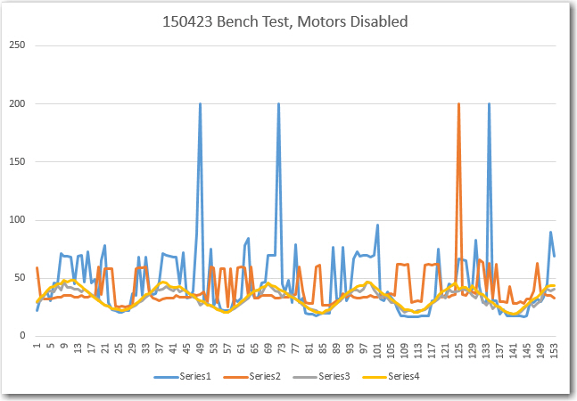
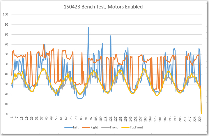
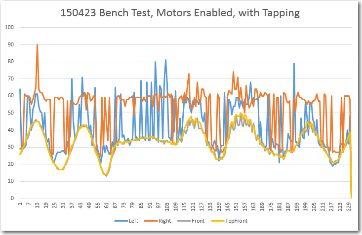
First, I ran a number of tests with the front sensor max distance still set at 255 so I could stay with the single-byte storage system, with and without the motors engaged, and with and without mechanically induced vibration (tapping vigorously on the side of the robot chassis) while moving it toward and away from my bench wall.

Test bench run with motors disabled, without any external tapping

Test bench run with motors disabled, without any external tapping

Test bench run with motors enabled, but no external tapping

Test bench run with motors enabled, but no external tapping

Test bench run, motors enabled, with external tapping

Test bench run, motors enabled, with external tapping

From these runs, it is clear to see that having the motors engaged and/or having an external disturbance does not significantly affect the sensor data quality.

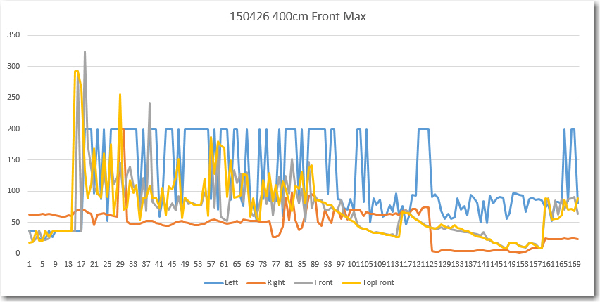
Next, I enabled 2-byte EEPROM storage and a 400 cm max distance for the two front sensors. Then I did a bench test to validate that EEPROM storage/retrieval was being done properly, and then ran another field test in the ‘slipper’ hallway.

Field test with all sensors and motors enabled, 400 cm max distance on front sensors

Field test with all sensors and motors enabled, 400 cm max distance on front sensors

The front and top-front sensor data still looks very crappy, until Wall-E gets within about 100 cm of the far wall, where it starts to look much better.  From this it is clear that opening up the front max distance from 255 to 400 cm did absolutely nothing to improve the situation.  Meanwhile, the offside side sensor readings are all over the place.

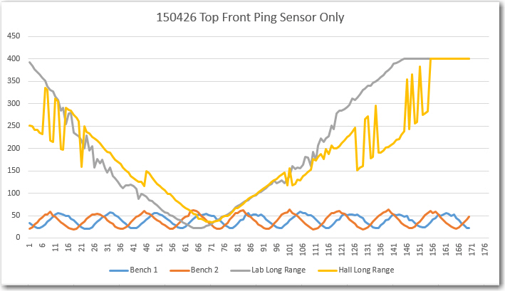
So, I have eliminated motor noise, mechanical vibration, and inappropriate max distance settings as the cause of the problems evident in the data.  After thinking about this for a while, I came to the conclusion that either there was still some intra-sensor interference, and/or the hallway itself was exhibiting multipath behavior.  To test both these ideas, I disabled the motors and all but the top-front sensor, and ran a series of 4 tests, culminating in a run in the ‘slipper’ hallway where I moved the robot by hand, approximating the somewhat wobbly path Wall-E normally takes.  The results are shown below.  In the first two tests I moved the robot toward and away from my test wall a number of times, resulting in a sinusoidal plot.  In the two long range tests, I started approximately 400 cm away from the wall, moved close, and then away again, back to approximately 400 cm.

Test run in my lab and in the  'slipper' hall, top front sensor only (400 cm max distance).

Test run in my lab and in the ‘slipper’ hall, top front sensor only (400 cm max distance).

The first two tests (‘Bench 1’ and ‘Bench 2’) validated that clean data could be acquired, and the ‘Lab Long Range’ test validated that the ping sensor can indeed be used out to 400 cm (4 meters).  However, when the field test was run, significant variation was noted in the 150-350 cm range, and there doesn’t seem to be any good explanation for this other than multipath.  And, to make matters worse, if one sensor is exhibiting multipath effects, it’s a sure bet that they  all are, meaning the possibility (probability?) of multiple first, second, and third-order intra-sensor interference behavior.

After this last series of tests, I’m pretty well convinced that the use of multiple ping sensors for navigation in confined areas with multiple ‘acoustically hard’ walls is not going to work.  I can probably still use them for left/right wall-following, but not for front distance sensing, and certainly not for ‘stuck’ detection.

So, what to do?  Well, back to Google, of course!  I spent some quality time on the web, and came up with some possibilities:

  • The Centeye Stonyman Vision Chip and a laser diode. This is a  very cool setup that would be perfect for my needs.  Very small, very light, very elegant, and (hopefully) very cheap laser range finder – see  https://www.youtube.com/watch?v=SYZVOF4ERHQ.  There is only one thing wrong about this solution – it’s no longer available! :-(.
  • The ‘Lidar Lite’ laser range finder component available from Trossen Robotics (http://www.trossenrobotics.com/lidar-lite).  This is a complete, self-contained LIDAR kit, and it isn’t  too big/heavy, or  too expensive (there might be some argument about that second claim, but what the heck).
  • The Pixy CMUCam, also available from Trossen (http://www.trossenrobotics.com/pixy-cmucam5).  This isn’t quite as self-contained as it  needs a separate laser and some additional programming smarts, but it might be a better fit for my application.

So, I ordered the LIDAR-lite and the CmuCAM products from Trossen, and they will hopefully be here in a week or so.  Maybe then I can make some progress on helping Wall-E defeat his nemesis – the evil stealth slippers!

Stay tuned…

Frank
Adventures with Wall-E’s EEPROM, Part V


Posted 04/22/15

In my last post I analyzed  a stuck/un-stuck scenario where Wall-E got stuck on a coat rack leg, and then got himself unstuck a few seconds later.  This post deals with a similar scenario, but with the evil stealth slippers instead of the coat rack, and this time Wall-E didn’t get away :-(.


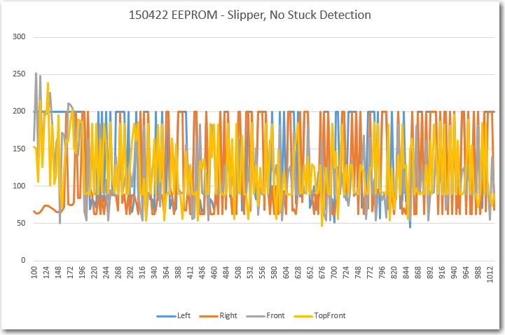
EEPROM data from Wall-E slipper run.  Note large variations on all four channels.

EEPROM data from Wall-E slipper run. Note large variations on all four channels.

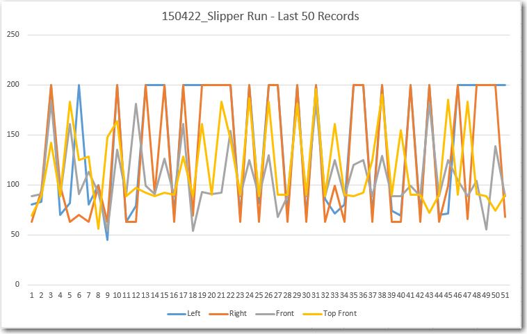
Last 50 records, showing large amount of variation on all four channels.

Last 50 records, showing large amount of variation on all four channels.

Analysis:

  • T = 09: Wall-E hits his nemesis, the evil Stealth Slippers
  • T + 37: Wall-E signals that it has filled the EEPROM.  No ‘stuck’ detection, so no sensor array data.
  • My initial impression of the 4-channel EEPROM record was “Geez, it’s just random garbage!”.  There does not appear to be any real structure to the data, and certainly no stable data from the left and right side sensors.  Moreover, the top front sensor – the one that was supposed to provide nice stable data even in the presence of the stealth slippers – appears to be every bit as unstable as the others – ugh!
  • In order to more closely examine the last few seconds of data, I created a new plot using just the last 50 or so records.  From this it is clear that both the left and right side sensor data is unstable and unusable – both channels show at least one max-distance (200 cm for the side sensors) excursion.  The front and top-front data doesn’t fare much better, with 4-5 major excursions per second.
  • The only bright spot in this otherwise panoply of gloom is that the front and top-front sensor data shows a lot of intra-sensor variation, meaning that this might be used to effect a ‘stuck’ declaration.  In the last 50 records, there are 4 records where ABS(front-topfront) > 85 (i.e. > MAX_FRONT_DISTANCE_CM / 3).  Looking more closely at the entire EEPROM record, I see there are 18 such instances – about one instance per 50 records or so, or about 1 per second.  Unfortunately, at least 6 of these occur in the first third or so of the entire record, meaning they occur  before  Wall-E gets stuck on the slipper.  So much for  that idea :-(.

Despite the gloom and doom, this was actually a very good run, in that it provided high-quality quality data about the ‘stealth slipper detection’ problem.  The fact that the data shows that one of my ideas for detection (the intra front sensor variation idea) simply won’t work, as that variation is present in  all the data, not just when Wall-E is stuck.  At least I don’t have to code the detection scheme up and then have it fail! ;-).

It is just barely possible that I have caused this problem by restricting the max detection distance for the front sensors to 250 cm in an effort to mitigate the multipath data corruption problem.  So, I’m going to make another run (literally) at the slippers but with the max front distance set out to 400 cm versus the existing 255 cm limit.  However, this will cut the recording capacity  in half, as I’ll have to use 2 bytes per record.  I can compensate for this by not storing the left and right sensor data, or by accepting a shorter recording time, or some combination of these.  One idea is to store the left & right sensor data as bytes, and the front sensor data as ints.  This will require modifying the EEPROM readout code to deal with the different entry lengths, but oh well….

Stay tuned…

Frank


Adventures with Wall-E’s EEPROM, Part IV

Posted 04/22/15

In my last post, I showed some results from Wall-E’s EEPROM data captures, including a run where Wall-E got stuck on the wife’s evil stealth slippers – and then unexpectedly got ‘unstuck’.  I couldn’t explain Wall-E’s miraculous recovery from the captured EEPROM sensor data, so I was left with two equally unpalatable conclusions; either I didn’t understand Wall-E’s program, or Wall-E was ‘seeing’ something besides what was captured in the EEPROM.
So, I decided to modify Wall-E’s programming to capture additional data when/if Wall-E got stuck – and then unstuck – on future runs.  The mods were described in the last post, but basically the idea was to capture the contents of both the 50-point front and top front sensor data arrays, along with the current values of all four sensors.  To do this I re-purposed  the first 100  EEPROM locations to store the sensor array data, figuring that the earliest points would be the least likely to be relevant for post-run analysis.

After making the mods, and testing them on the bench in debug mode, I took Wall-E out for another field trial, hoping he would do the same thing as before – namely getting stuck and then un-stuck on/from the evil stealth slippers.

As it turned out, Wall-E’s next run produced good news and bad news. The good news is that Wall-E did indeed get stuck and then un-stuck, providing some very good decision data.  The bad news was that it got stuck on a coat rack leg (an easier problem for Wall-E) instead of the stealth slippers.  Still, it  did provide an excellent field validation of the new data collection scheme, as shown below.

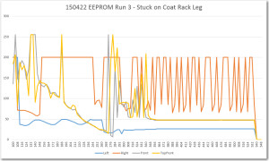
Remaining EEPROM Contents at the point where Wall-E declares 'Stuck'.

Remaining EEPROM Contents at the point where Wall-E declares ‘Stuck’.

Top and Top Front Sensor Array Contents at the point where Wall-E declares 'Stuck'

Top and Top Front Sensor Array Contents at the point where Wall-E declares ‘Stuck’

Analysis:

  • T + 13:  Wall-E gets stuck on a coat rack leg.  He got stuck because I  hadn’t yet updated the left front bumper to the new non-stick style, but this was a good thing ;-).  Just before Wall-E hits the leg, the left sensor distance reading changes rapidly from about 40 cm to about 20, as the left sensor picks up the coat rack leg on its left.
  • T + 13-15: Wall-E tries to drive around the coat rack leg it is stuck on, causing it to turn about 45 degrees to the left. During this period the right, front, and top-front sensor readings vary wildly, but the left sensor reading stays quite stable (almost certainly  reading the distance to the coat rack leg on the left).
  • T + 16:  Wall-E has stopped moving, and consequently the top and top-front  sensor readings settle down.  Interestingly, the right distance sensor readings  don’t  settle down, even thought there are no obstacles within the max detection distance (200 cm) on that side – no idea why.
  • T + 20: Wall-E declares the ‘stuck’ condition.  This is almost certainly due to  the total deviation of the current contents of  the front sensor reading arrays falling below the threshold (5 cm in this case).  From the data, the front sensor array deviation is 4 cm, while the top-front deviation is still high (161) due to a 209 value that hasn’t quite yet fallen off the end.

So, the captured for this run is entirely consistent with the stuck condition and recovery, with the possible exception of the anomalous right sensor readings that should show a constant 200 cm but doesn’t for some unknown reason.

Next up – another try at getting Wall-E stuck on the stealth slippers, with (hopefully) a ‘stuck’ condition’ detection to boot!

Stay tuned…

Frank