Posted 11/08/2015
I’ve been having some problems lately getting good prints on my Printrbot Simple Metal 3D printer, and after a lot of inet research I concluded the problem was a warped print bed. The bed that comes with the Simple is pretty nice, but just not thick enough IMHO to avoid some warping. And once the bed becomes even a little bit non-planar, then the very nice ‘auto-leveling’ (more accurately ‘bed tilt compensation’) ceases to be very useful.
There was some discussion about putting a glass plate down over the original bed, which takes care of the non-planar issue, but then the Hall-effect metal bed sensor can’t ‘see’ the metal print bed through the glass plate, unless the glass plate is too thin to do any good. What to do?
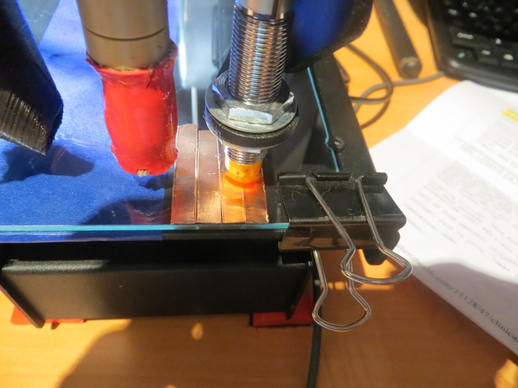
I’m a long-time Electrical Engineer and antenna researcher, and so it occurred to me that I might be able to fake out the bed sensor by applying some adhesive-backed metal tape to the top of a glass plate, thereby establishing a new ‘zero’ reference at the top surface of the glass plate. I ran some simple experiments, and found that the bed sensor worked fine with even very thin strips of just about any metal, including copper. Since I knew I could get copper tape in various thicknesses and widths, I thought this idea might be worth a try.
The glass plate:
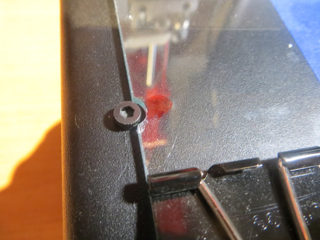
I remembered seeing a post somewhere that someone had found that a popular picture frame size worked just great for the Printrbot Simple Metal print bed, so I headed over to my local JoAnne’s fabric to see what was available. I found lots of cheap picture frames in various sizes, but nothing that even remotely approached a good size for my print bed – bummer. So, I decided to go the custom route, and, after carefully measuring my bed, got a piece of 3/32″ (~2.3mm) glass cut to 9.5 x 6.5″. I brought the piece home and carefully smoothed the edges with my belt sander (a sander drum attachment for a drill would work also). Unfortunately, when I laid the piece on my print bed, I discovered I had screwed up – the 9.5″ dimension was slightly too large, and the pieced didn’t quite fit between the two sets of mounting screws. I was really bummed out, until I realized I might be able to recover from this disaster by simply grinding cutouts for the screwheads, thereby converting a ‘bug’ into a feature! ;-). Indeed I was able to do this with a Dremel tool and a small grinding bit, and when I was finished I had a nice, self-registering glass plate for my Printrbot!
The Sensor Tape:
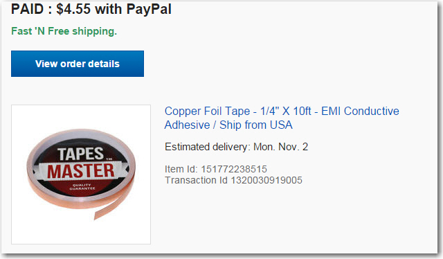
I didn’t have any adhesive backed copper tape handy (I used this stuff by the roll in my prior life as a research scientist, but didn’t think to take any with me into retirement), so I tolled the net for a while for sources. I finally wound up ordering a 10′ roll of 1/4″ adhesive-backed copper tape from eBay
Assembling the new Print Bed:
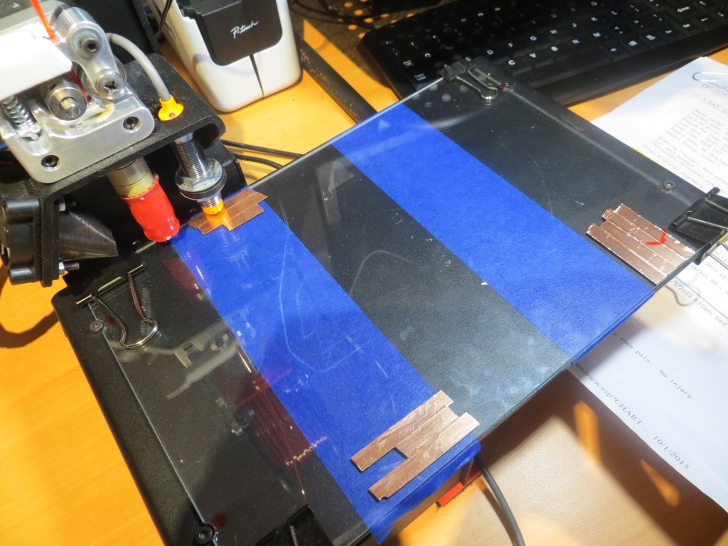
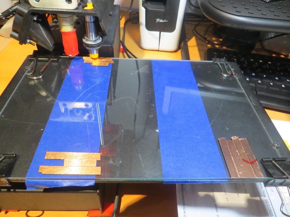
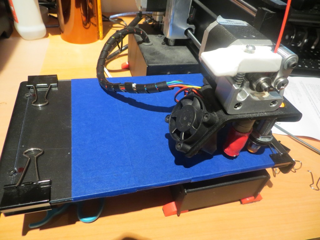
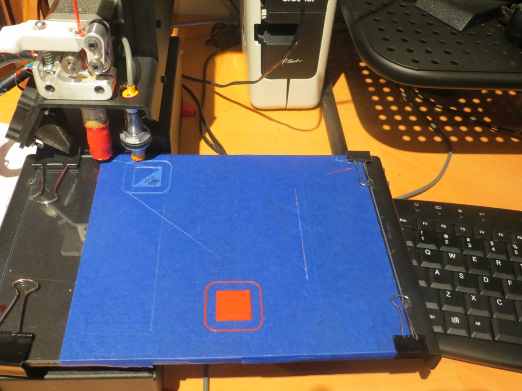
I used heavy-duty document clips to hold the glass plate down on the original print bed, and then placed copper tape patches at the X/Y home location and the two ‘slope compensation’ sensing points, and then covered the entire thing with blue painter’s tape to provide the same first-layer adhesion as before.
Testing:
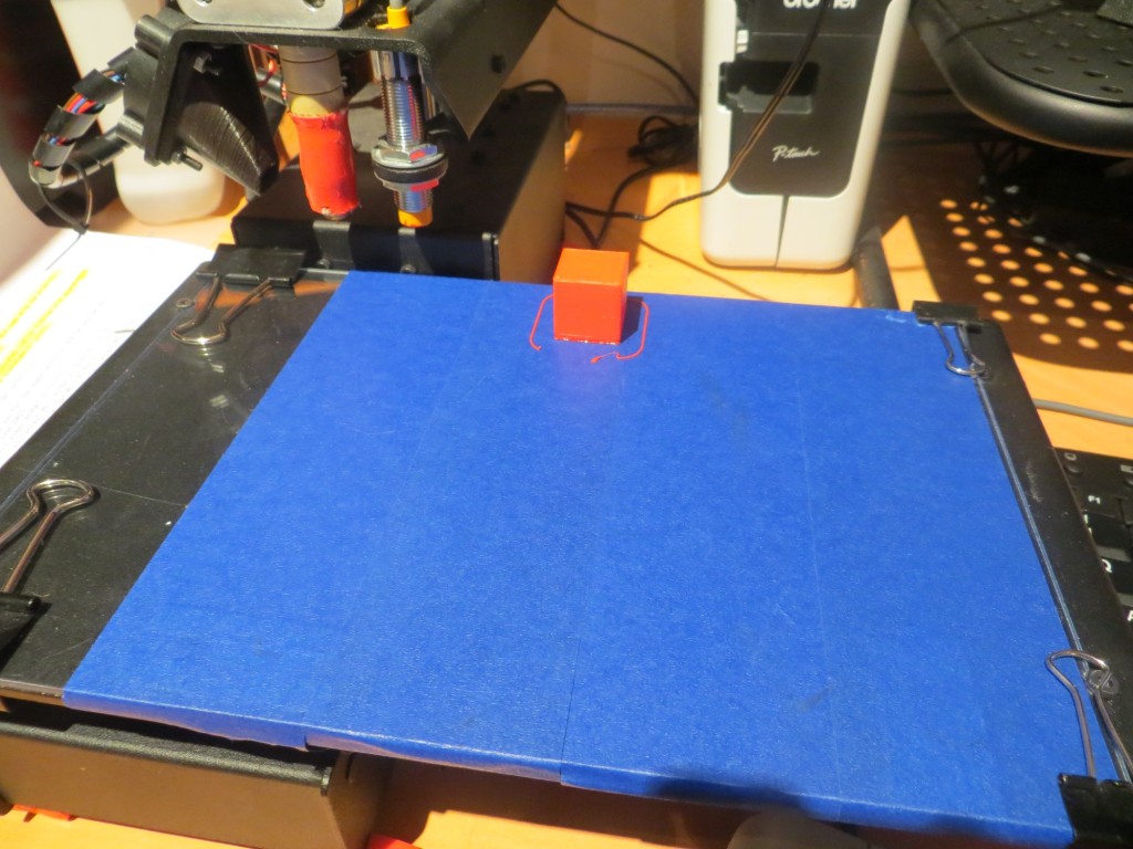
I used a 20mm hollow cal cube as my test object, starting at a point near the X/Y home position. As expected, I had to adjust the Z offset some, and wound up with a Z offset of about -0.8 to get a decent print.
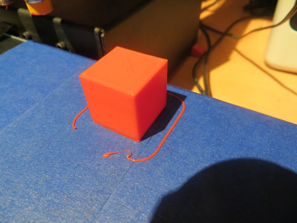
Then I tried moving the cube around on the print bed, and found that I had to keep moving the Z offset further negative as I moved the print position away from the X/Y home position. To get the cube to print properly, I would up with a Z offset of -2.0mm, way more than I had expected, and then when I tried to move the print back to near the X/Y origin with the same Z offset, I got the extrusion drag marking shown – bummer!
After seeing the above problem occur, I tried to figure out what was going wrong, and having a heck of a time with it. Here’s what I know:
- The Z offset required to get decent first-layer adhesion gets markedly more negative the further away the print position is from the X/Y home position
- Trying to print near the X/Y home position with the Z offset required for a position far away from X/Y home causes extrusion head dragging.
- However, in a somewhat contradictory finding, if I manually move the extrusion head position arm (the Y axis, I think) toward the outer edge of the print bed, it starts to drag about halfway across for X values near home, and this condition becomes more marked when the bed is manually moved in the positive X direction (to the left looking at the front of the printer). In other words, when moving the extrusion head in manual mode, it appears the print bed has a marked upward slope as X & Y increase, causing significant head drag. However, when printing, the opposite effect seems to occur, where the print bed appears to have a marked downward slope as X/Y increase. This makes no sense at all!
So, at the moment I’m officially baffled. In manual mode, the printrbot behaves as if the bed is sloped upward as X & Y increase, but in printing mode (where I assume the ’tilt compensation’ is in effect), the printrbot behaves as if the bed is sloped in the opposite direction. What gives!?
More to come (I hope)
I have the same setup and the exact same problem. I find that on one print the extruder is way too close to the bed towards the back of the bed and on the next print its less so.
Sean,
Take a look at my latest post on this subject (http://gfpbridge.com/2015/12/glass-print-bed-printrbot-simple-metal-part-v/). Here I used a cheap Harbor Freight dial indicator to level the bed, and relocated the Z-axis probe to the side of the printrbot so it would sense the metal case vs the (now covered) metal print bed.
After this modification, I have had no problems at all printing anywhere on the bed – its great!