After getting the Pulsed Light spinning LIDAR system working on Wall-E, I added motor control and navigation code to my LIDAR test code, just to see how if the LIDAR could be used for actual navigation. As it turned out, I discovered two problems; one was related to missed LIDAR distance measurements that got loaded into the nav table as ‘0’s, (see my previous post on this issue) and the other was that interrupts stopped occurring after some indeterminate time after the motors were enabled. Of course, these glitches just had to occur while my control-systems expert stepson Ken Frank and his family were visiting. I told him about the symptoms, and speculated that maybe noise from the motor control PWM pulse train was coupling into the high-impedance interrupt input and overloading the interrupt stack with spurious interrupts. This input is driven by the analog signal from the tach wheel sensor (IR photodiode), and the signal line runs along the same path as one of the motor drive twisted pairs. Without any hesitation, Ken said “well, if you had converted that analog signal to digital at the source, you wouldn’t be having this problem”. This was absolutely correct, and not a little bit embarrassing, as I distinctly remember teaching him all about the perils of low-level analog signals in proximity to high-level motor currents! I guess it’s better to receive one’s comeuppance from a loved family member and fellow EE, but it’s still embarrassing ;-).
In any case, it’s now time to address the EMI problem. I’m not absolutely sure that the issue is motor currents coupling into the analog sensor line, but it has all the earmarks; it doesn’t happen unless the motors are engaged, and the sensor line is in close proximity to one of the high-current motor drive twisted-pairs for some of it’s length. Moreover, I neglected to follow basic low-level analog handling protocol by using a twisted pair with a dedicated return line for this signal, so at the very least I’m guilty of gross negligence :-(.

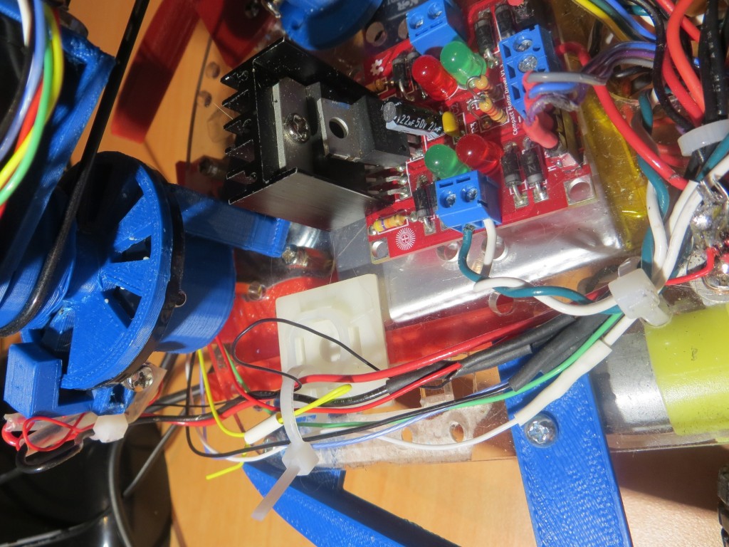
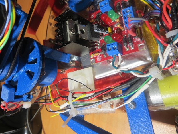
Black loop is part of the analog signal run from photodiod sensor on left to Uno (not shown). Note green/white motor drive twisted pair
In the screenshot above, the thin black wire (visible against the white stay-strap mounting square background) is the analog output line from the tach wheel sensor circuit. This line runs in close proximity to one of the motor drive twisted pairs for an inch or so (extreme right edge of the above image) until it peels off to the right to go to the Arduino Uno.
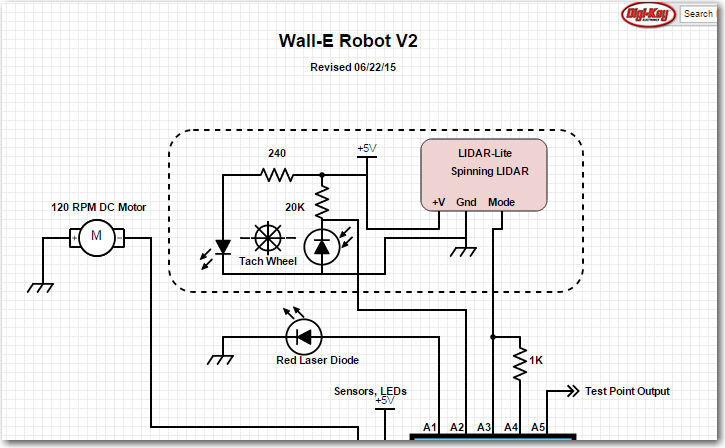
As shown below, this circuit has an equivalent output impedance of about 20K ohms (20K resistor in parallel with the reverse bias impedance of the photodiode), so while it’s not exactly a low-level high-impedance output, it’s not far from it either. The black wire in the photo is the connection from the junction of the 20K resistor and the photodiode to pin A2 of the Uno.
Although I have looked at the A2 input pin with an Oscilloscope (my trusty Tektronix 2236) and didn’t see anything that might trigger spurious interrupts, it doesn’t have the bandwidth to see really fast transitions. And, as I was once told many many years ago in the TTL days, “TTL circuits can generate and respond to sub-nanosecond signals”. Although TTL has gone the way of the dinosaurs (and old engineers like me), the old saw is still applicable.
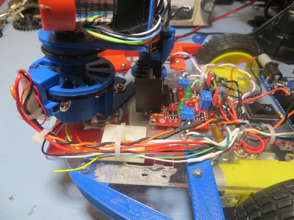
So, what to do? Well, the obvious starting place is to replace the single wire signal run with a twisted pair, adding a dedicated return wire. In the past, just replacing a single line with an appropriately terminated twisted pair has shown to be remarkably effective in reducing EMI coupling problems, so I’m hoping that’s all I have to do. The following photo shows the modification
In the above photo, the orange/black twisted pair replaced the single-line tach wheel sensor signal line. The orange wire is the signal wire and the black wire is the dedicated return line. The return line is routed to a nearby ground pin on the Arduino Uno. As an additional precaution, I installed a 0.01 μF cap between the signal input and the ground pin.
After these modifications, I fired up Wall-E with the motors engaged, and was relieved to find that tach wheel sensor interrupts appear to continue indefinitely, even with the motor drive engaged – yay!!


Pingback: Wall-E Has More Interrupt Issues - Paynter's Palace