The ‘minimalist’ joystick model from Part 4 was barely out the door before I had another brainstorm. I have always done some of my best thinking while in bed, waiting for sleep to come. My brain is still going over the events of the day, teasing at unsolved problems, and sometimes just as I’m about to drop off, a possible solution or different approach to a problem becomes clear.
In this particular case, it occurred to me that the joystick might not be the best place for a remote control caddy – maybe it would be better on the flap handle instead! This was such a powerful idea that I practically leaped out of bed, padded barefoot down the hall to my office/laboratory, wrote “Flap Handle!” on a post-it note and stuck it to my primary PC monitor. In the light of the next day, awake, alert, and with coffee in hand the idea seemed even better.
Pros:
- In a flapped ship, the pilot’s left hand is almost always on the flap handle, and there aren’t any other controls or switches there to interfere with a remote control pad.
- The flap handle is on the side of the glider, so wire routing should be easier.
- Flap handle mechanical motion is also much more constrained than joystick movement, so interference with other cockpit objects/controls becomes a non-issue.
- Button actuation with the left thumb should be much easier, assuming the CN remote caddy could be angled correctly with respect to the flap handle.
Cons:
- The flap handle juts out over the pilot’s left leg, so anything mounted to the end of the flap handle is vulnerable to damage as the pilot gets into or out of the glider
- The cable from the remote control to the ClearNav (CN) has to get from the end of the flap handle to the side of the glider somehow, and the length of the cable run to the CN changes significantly with the forward and aft motion of the flap control
- Getting the right caddy/flap handle relative orientation might be tricky.
A completely independent, but quite significant ‘Pro’ for this idea was that it offered a perfect vehicle to demonstrate the power and flexibility of the 3D printing paradigm to my two grand-children (and their parents) who happened to be visiting over the Labor Day weekend. As it turned out, Danny (12 years old and younger of the two) dived in with great enthusiasm, and by the end of his stay was doing design modifications on his own!
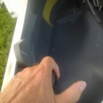
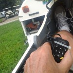
When I broached this idea to my friend, he was also enthusiastic, and sent photos detailing the flap handle dimensions and a photo with the remote control held in what he thought might be the correct orientation.
Armed with this information, Danny and I started work. The overall strategy was to constuct a new handle, shaped more or less like the old one, but with the CN remote caddy section from the previous ‘minimalist’ joystick grip design (see Part IV) attached to the end at an orientation approximating the one shown above.
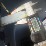
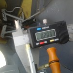
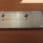
The first thing I did was to take a short trip to the local hardware store and purchase a 3′ section of 1″ x 1/4″ aluminum flat stock, slightly larger in both dimensions than the actual flap handle. I figured we could use this for initial hole sizing/testing, and adjust later if necessary. Next we designed and printed a test piece to confirm we had the rectangular hole size correct (we did). Next we started designing the replacement handle, incorporating the slot from the above test piece. Somewhere this step, we inadvertently scaled the handle and its internal slot down by a factor of about 2/3, so the first couple of handle prints came out way undersized. Fortunately, we were watching the print as it built up from the bottom, so we recognized the problem pretty quickly and aborted the print after 1/4″ or so. This actually turned out to be a pretty cool technique; we would make a full-length design, but only print a few mm or so, as the cross-section was more or less uniform throughout. As we got closer to what we thought would be a final design, we would let the print continue longer, finally letting the print go to completion. This way we could iterate much faster, and save filament too! ;-).
By about Rev 3 we had a full-sized constant-cross-section cylindrical flap handle printed up that we could slide onto the metal flap handle simulator, but we soon determined it was way undersized for an adult hand (it fit Danny, but…). So, back to TinkerCad for more revisions. Along the way, we also tried out some ideas for creating finger-grip indentations on the front side of the grip, and a corresponding palm indentation on the back side. As it turned out, we were able to use TinkerCad’s ‘Round Roof’ (a semi-cylinder) object for both – at a small scale for each finger indentation, and at a larger scale for the palm indentation.
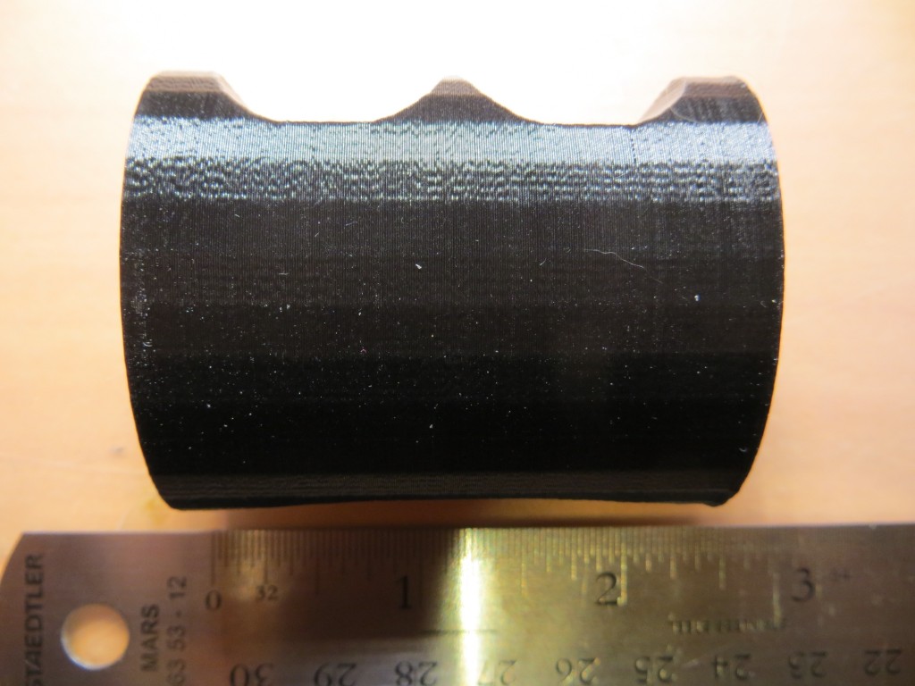
So now we had a basic flap handle grip, with finger and palm indentations and a rectangular hole for the flap handle. We still needed a way to attach the CN remote caddy to the end, and we needed some way of getting the control cable down the flap handle to the side of the glider. Our first run at this was a cylindrical cutout in the side of the grip. The idea was that the control cable could be pressed into the cutout through a small gap in the side of the grip, but wouldn’t come back out again without some effort, thus allowing for a smaller diameter hole because the end connectors (telephone style RJ-11’s) wouldn’t have to be accommodated. This was an OK idea in theory, but in practice we were stymied by a limitation in the ‘slicing’ software that converts the solid object model into thin wafer-slices that the 3D printer can handle. The slicer software kept opening up the gap to the point where the cable wasn’t retained – it would just fall right back out again. So, we took a closer look at the connectors and determined that although a 12 mm round hole would be required, we could get away with a 9 x 9 mm square hole! The smaller square hole dimensions would allow us to put the hole entirely inside the flap grip and still not interfere with the main rectangular hole for the flap handle itself – ah, the wonders of 3D printing! ;-).
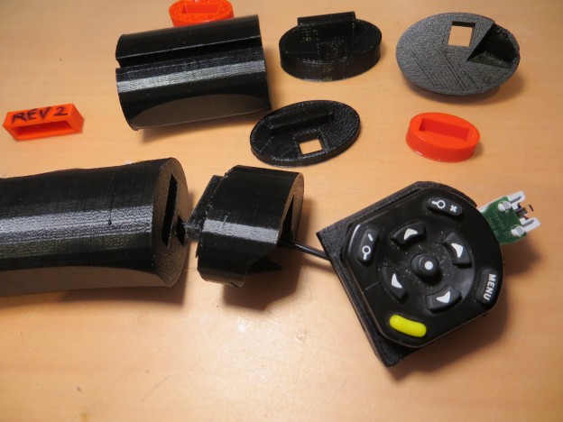
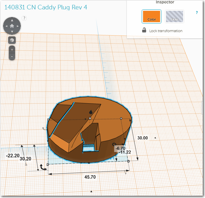
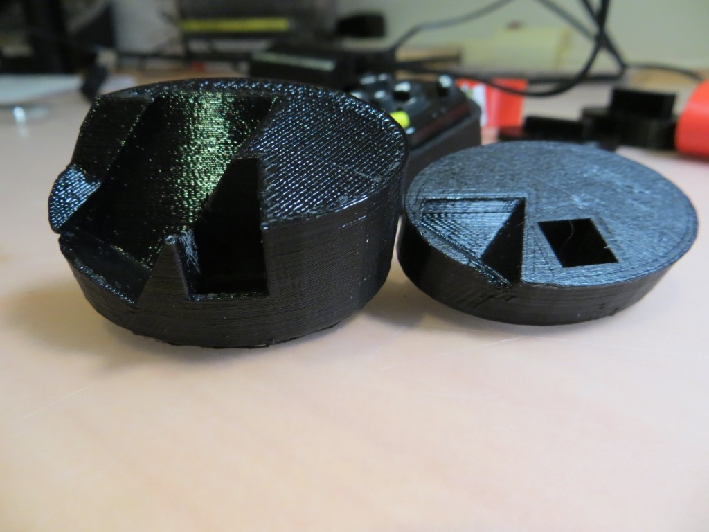
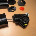
Next we tackled the problem of how to connect the CN remote caddy section from the ‘minimalist’ joystick grip model (See Part IV) to the flap handle grip. We decided that if we carried the rectangular flap handle hole all the way through the grip, and made the grip a bit longer than the actual handle, we could use the hole as a socket, and make a corresponding ‘plug’ section that would mate with the CN caddy. We created the ‘plug’ section by simply slicing off about 1/4″ of the handle into its own part, changing the rectangular hole to a rectangular solid, and then mating that part with the CN remote caddy. However, we quickly discovered that while it would be possible to print the combined part, it would be ugly, as the combination would require an exorbitant amount of support material due to the weird mating angle. So, we sliced and diced yet again, and printed the plug and caddy sections as independent parts (although we did print them at the same time) and glue the two together post-print. As it turned out, the first revision of the plug didn’t have a big enough indentation for the caddy, so the resultant piece wasn’t strong enough. Back to TinkerCad, where we extended the plug a bit to provide more ‘meat’ for the mating interface. This also necessitated a slight modification to the design of the cord handling tunnel, as it had to be ‘bent’ slightly at the end to allow the cord to be threaded behind the remote caddy and into the tunnel.
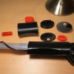
At this point we had designed and printed all the required pieces – the flap handle grip, the ‘plug’ to connect the grip to the remote caddy, and the caddy itself. All that remained was to glue the caddy to the plug (which turned out to be a mini-project in itself) and get the two pieces (caddy/plug and grip) down to John for him to try out on the actual glider. Stay tuned for the results! ;-).
- Completed grip system showing all three parts
- Completed system, with plug and caddy mated
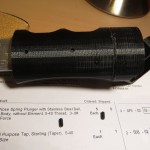
- Completed grip
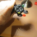
- Complete grip showing remote caddy orientation
- Flap grip with ball-nose spring plungers installed for better fit with flap control bar
- Flap handle simulator with ‘dimples’ installed for ball-nose spring plunger detent
As a not-insignificant side note to this project, my 12 year-old grandson got a great introduction to the world of 3D printing, and quickly became as much a participant as a spectator. The TinkerCad software GUI is very intuitive, and easily passed the 12 year-old usability test. By the end of his 2-day stay with us, he was designing parts in TinkerCad, downloading the STL files to my Linux box, and running my PrintrBot printer to actually print the parts, all with little or no supervision on my part. In fact, the only thing Danny had real trouble with was getting the printed parts off the print bed (protected by blue painter’s tape) because that required a bit more strength and precision with the removal tool (wood chisel with a 1/2″ blade) than he was able to muster.
Frank
