A while ago, the clock/time display on our microwave started having problems; it’s a 7-segment vacuum-flourescent display, and a couple of the segments a no longer lighting up. Instead of “End”, we now see “Erd”, and the clock is getting harder to read. The microwave itself is still running fine, but because this particular display is our primary time display in the house (aside from our phones), not having a good clock display is annoying.
I investigated getting the appropriate repair part for the display, but that module costs more than the entire microwave did originally, so that didn’t seem like a practical idea. And while I can get a cheap stick-on clock for just a few bucks, what’s the fun in that?
So, I’m in the middle of a design project to build a digital clock to replace the one on the microwave. At first I built up a clock using a Teensy 3.2 and one of my spare Nokia 5110 LCD displays, but that turned out not to be very practical, as the display is basically unreadable from more than just a few feet away, with or without backlighting.
So, I started looking around for better displays, and ran across the ILI9341 TFT display with a touch-sensitive screen. Even better, this was available with Teensy-optimized drivers, as shown here – what a deal! I started thinking that with a touch-sensitive screen, I might be able to implement some on-screen buttons for setting the time, which would be way cool!
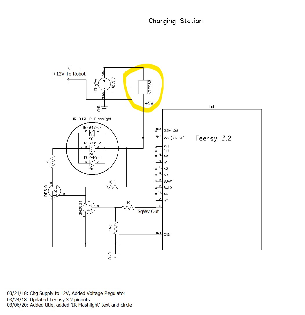
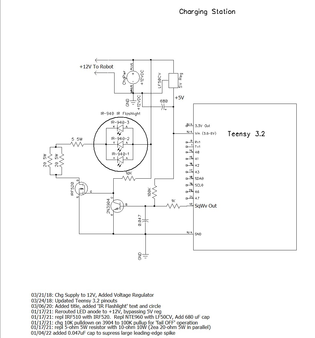
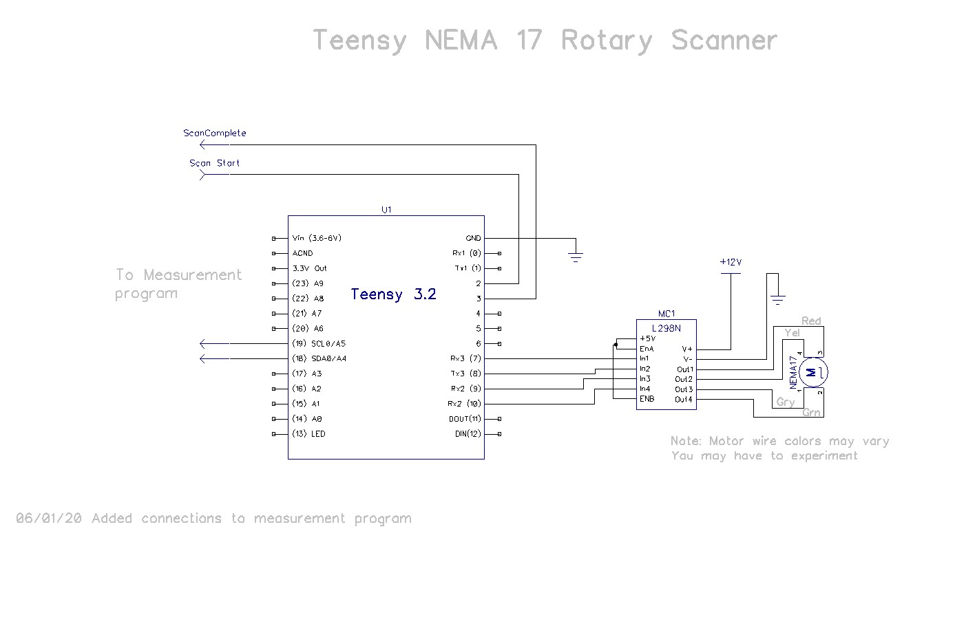
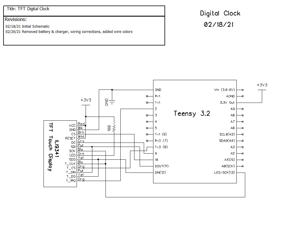
So, I ordered two of these displays from PJRC, and started working on the design. Here’s the initial schematic

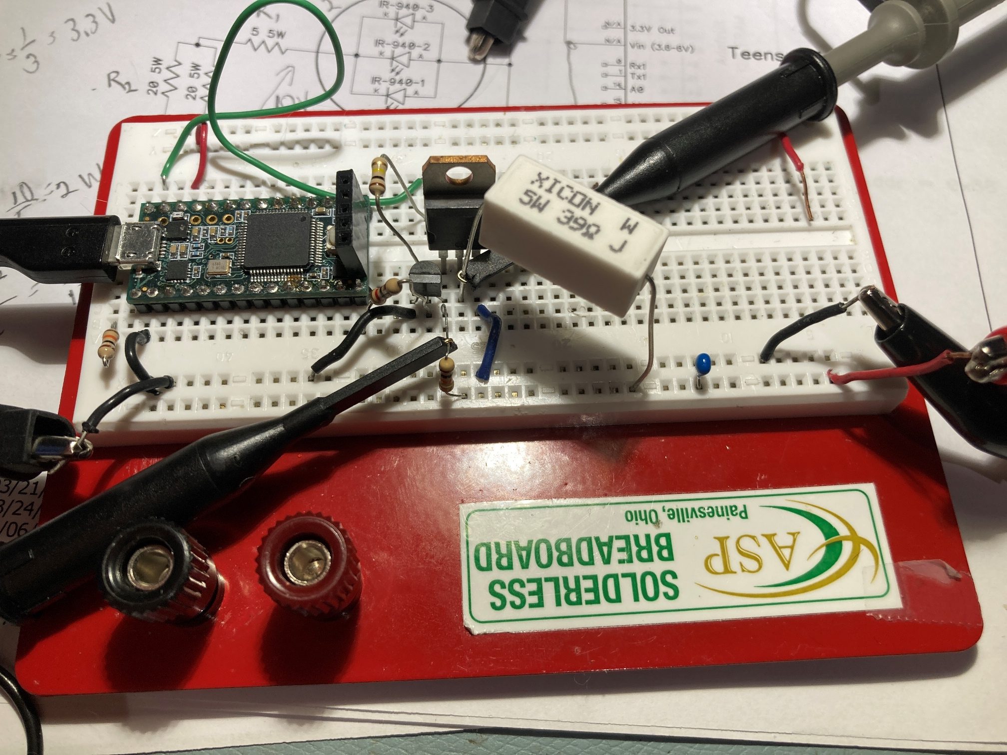
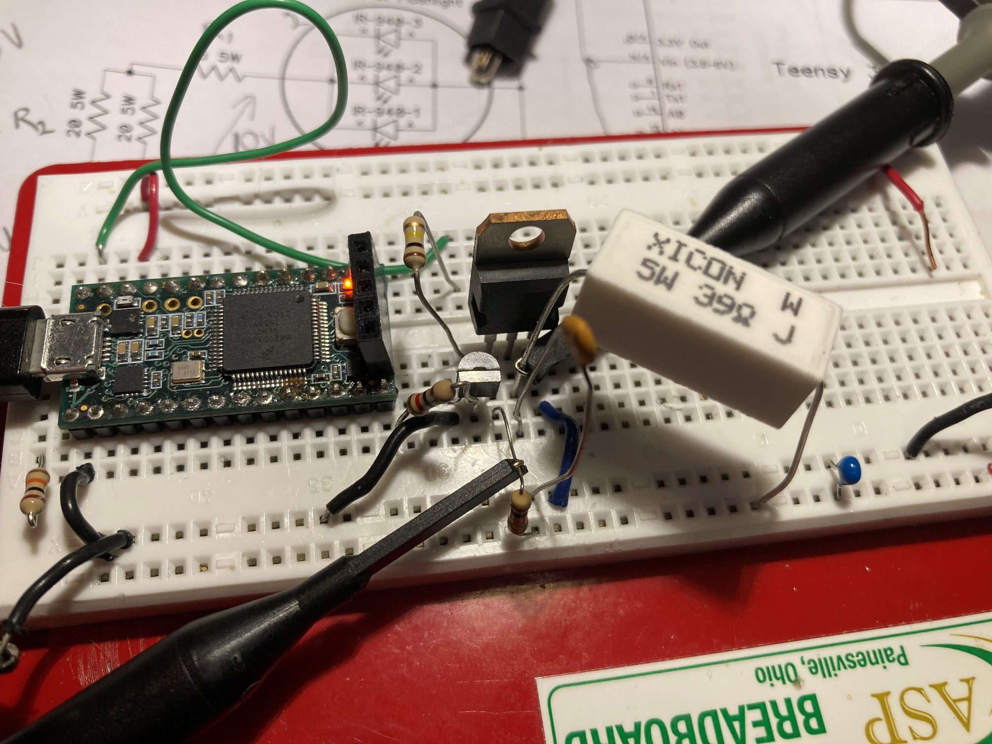
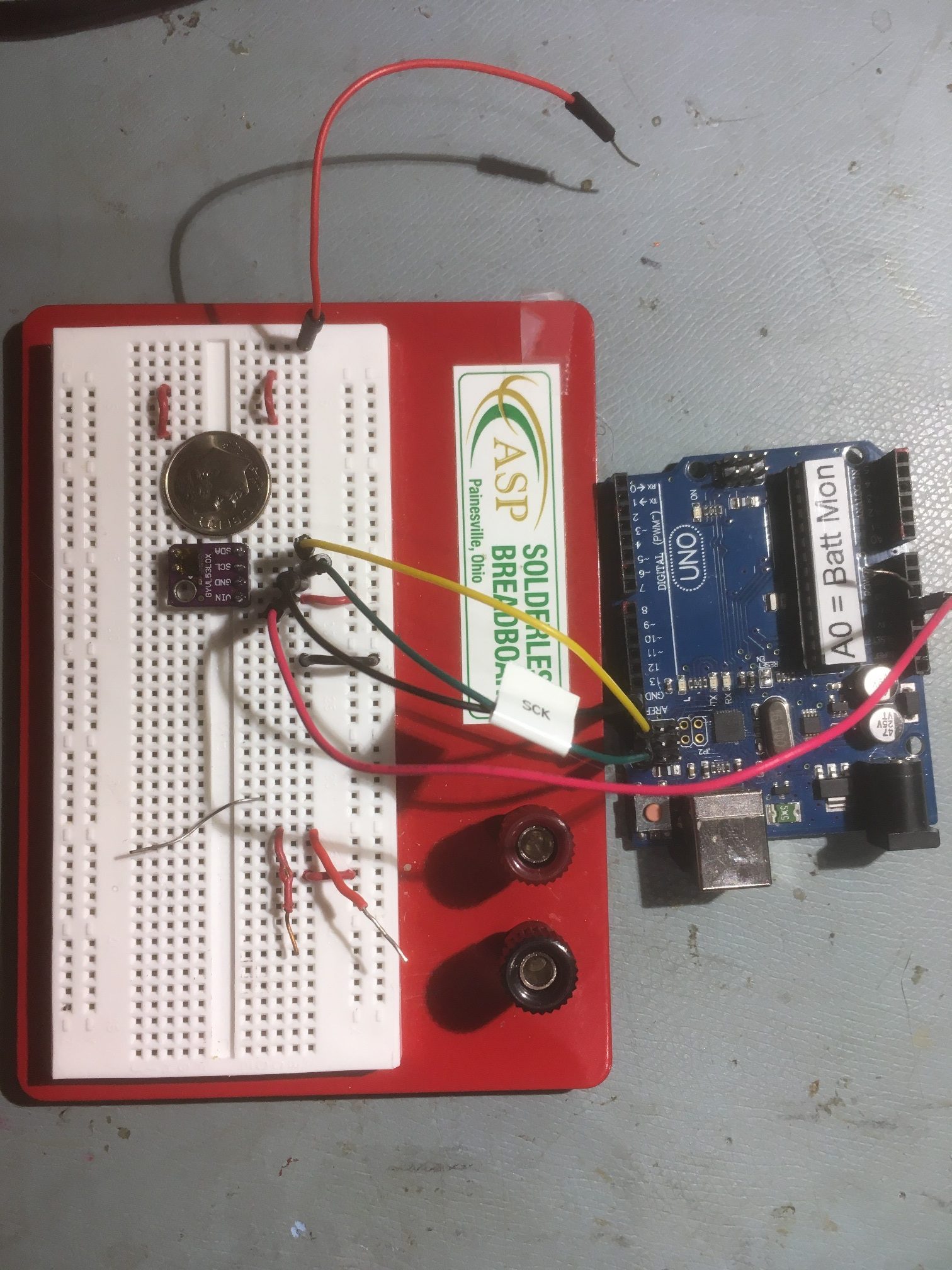
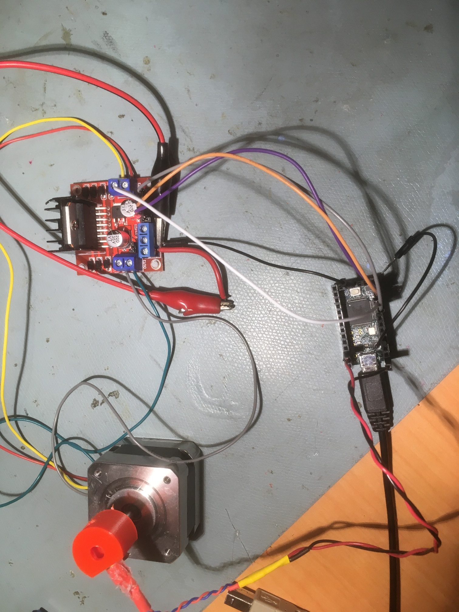
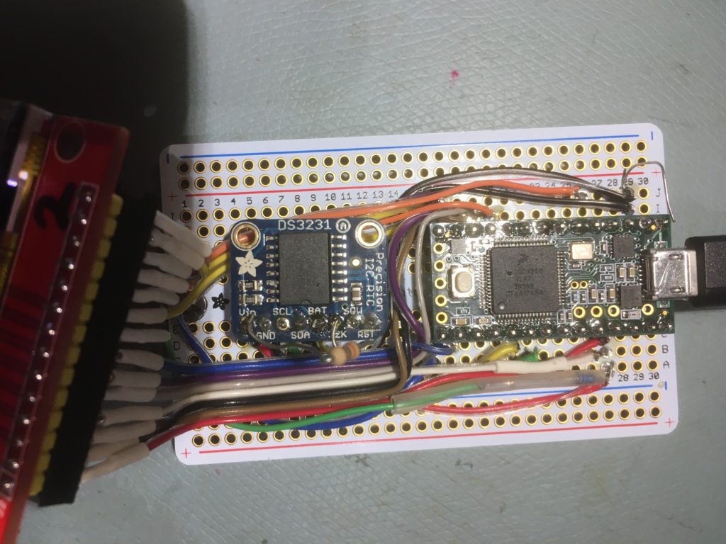
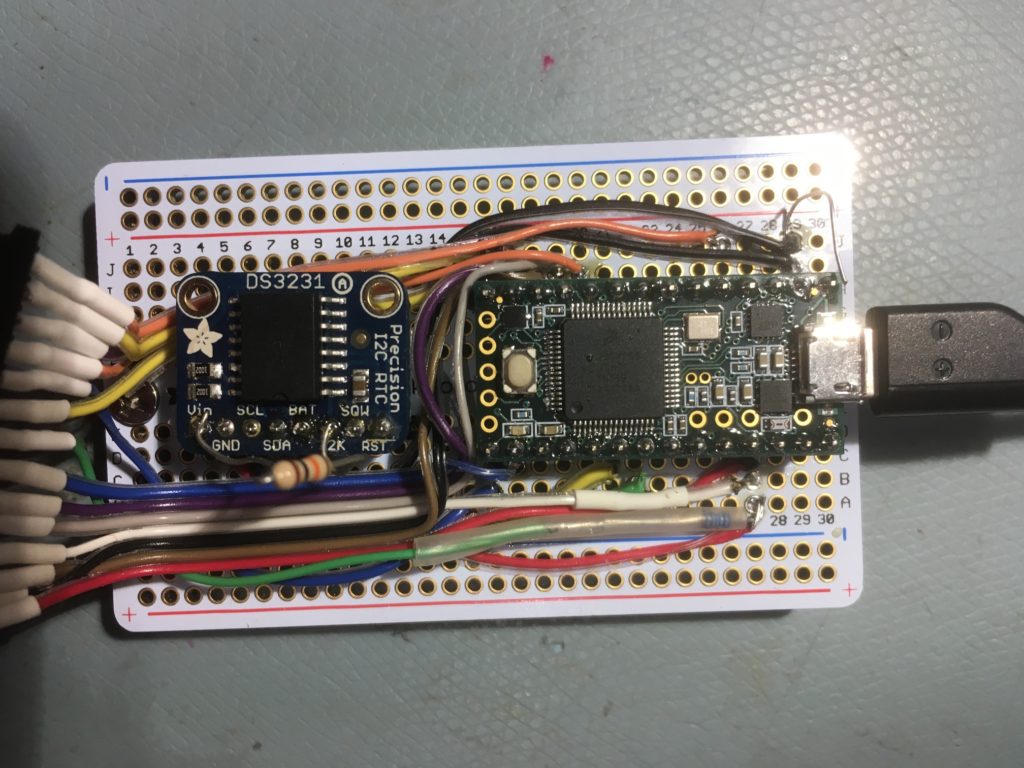
Here’s my initial breadboard setup:
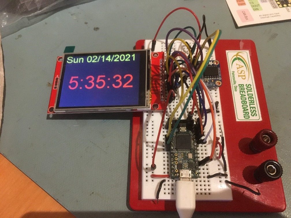
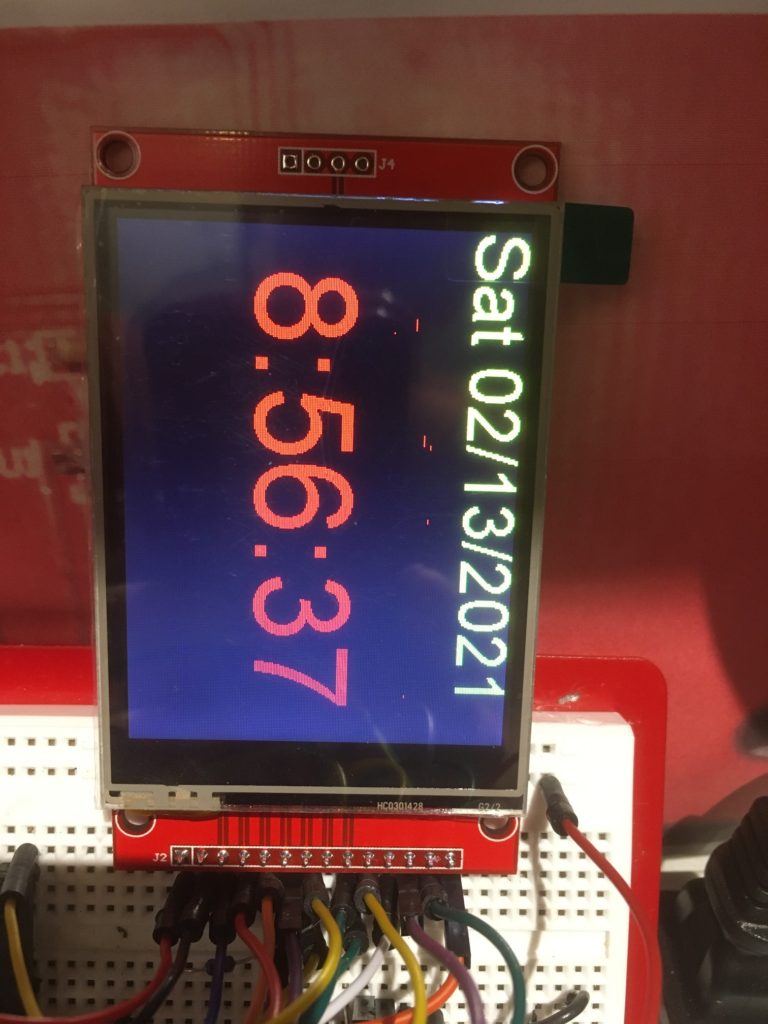
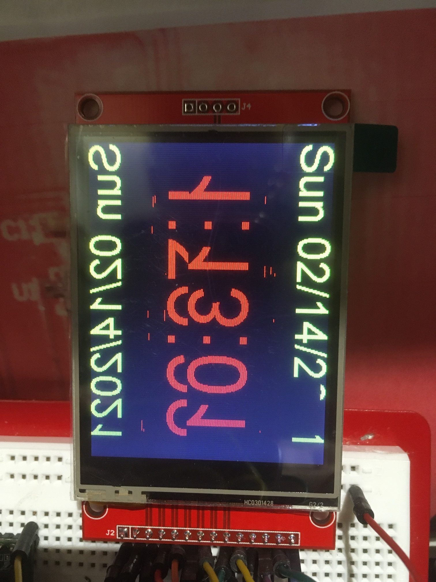
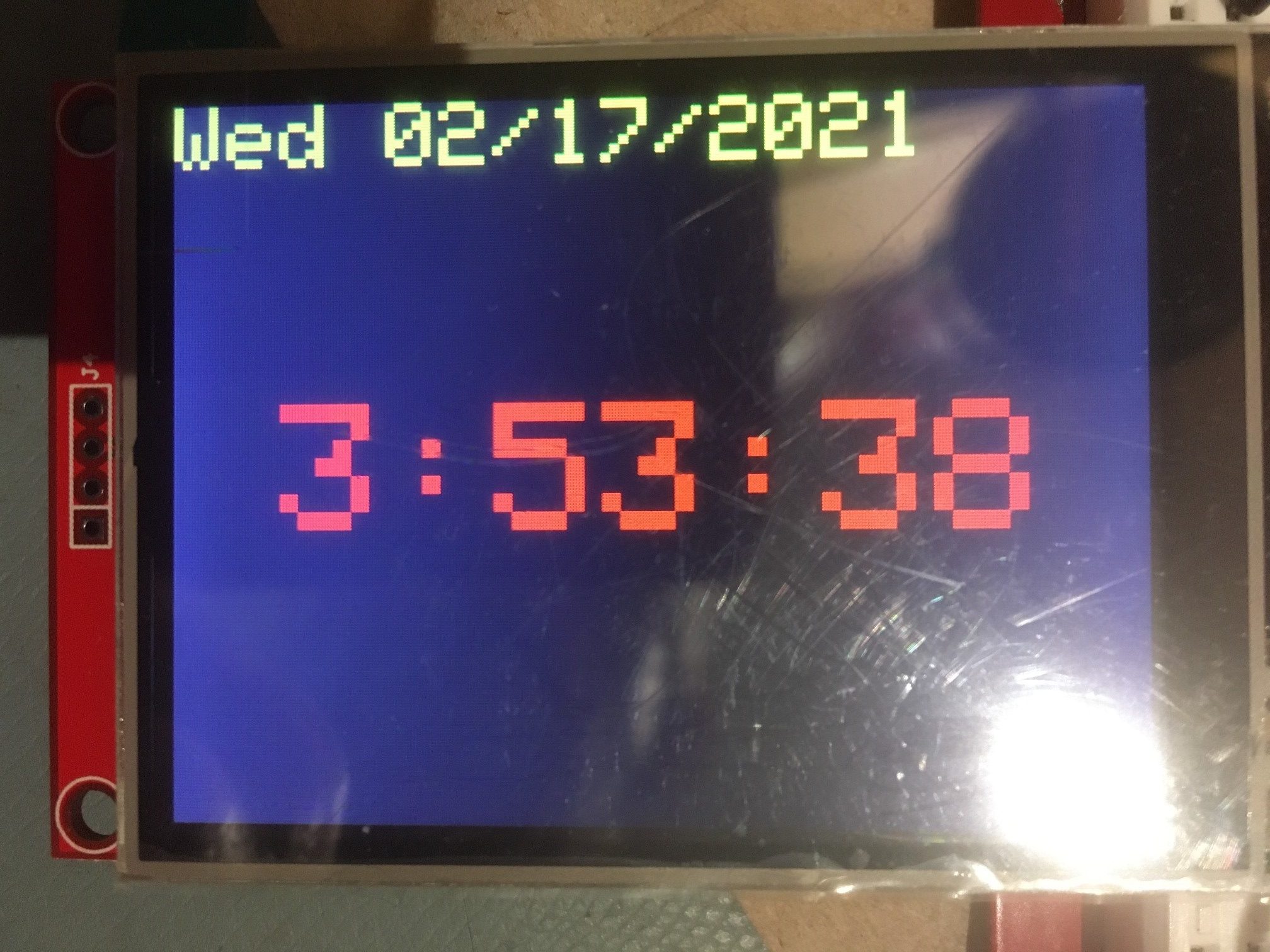
I originally used the Arial proportional font provided by the library, but I discovered that it produced bad artifacts after a few hours, as shown below: The only way to avoid these artifacts is to refresh the entire screen on every pass through the 1-second timing loop, which causes a very annoying ‘blink’. Eventually I figured this out, and changed to a non-proportional font, as shown below;
After just a few minutes 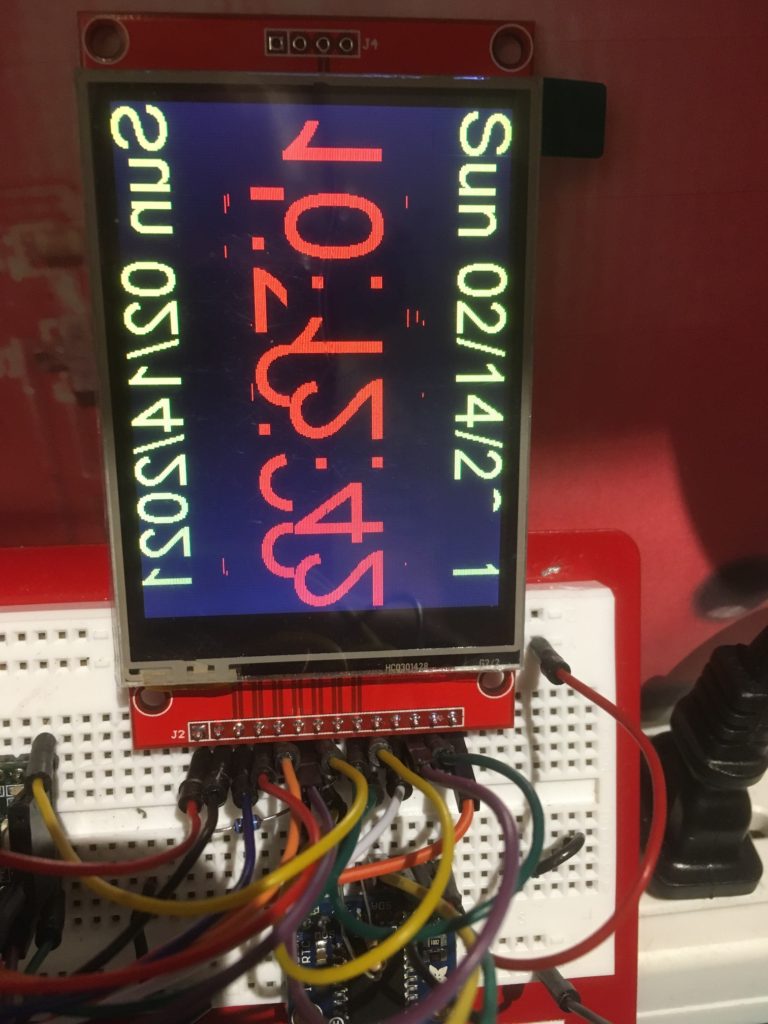
After several hours 
After several hours
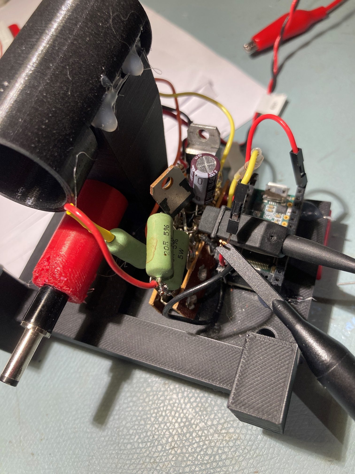
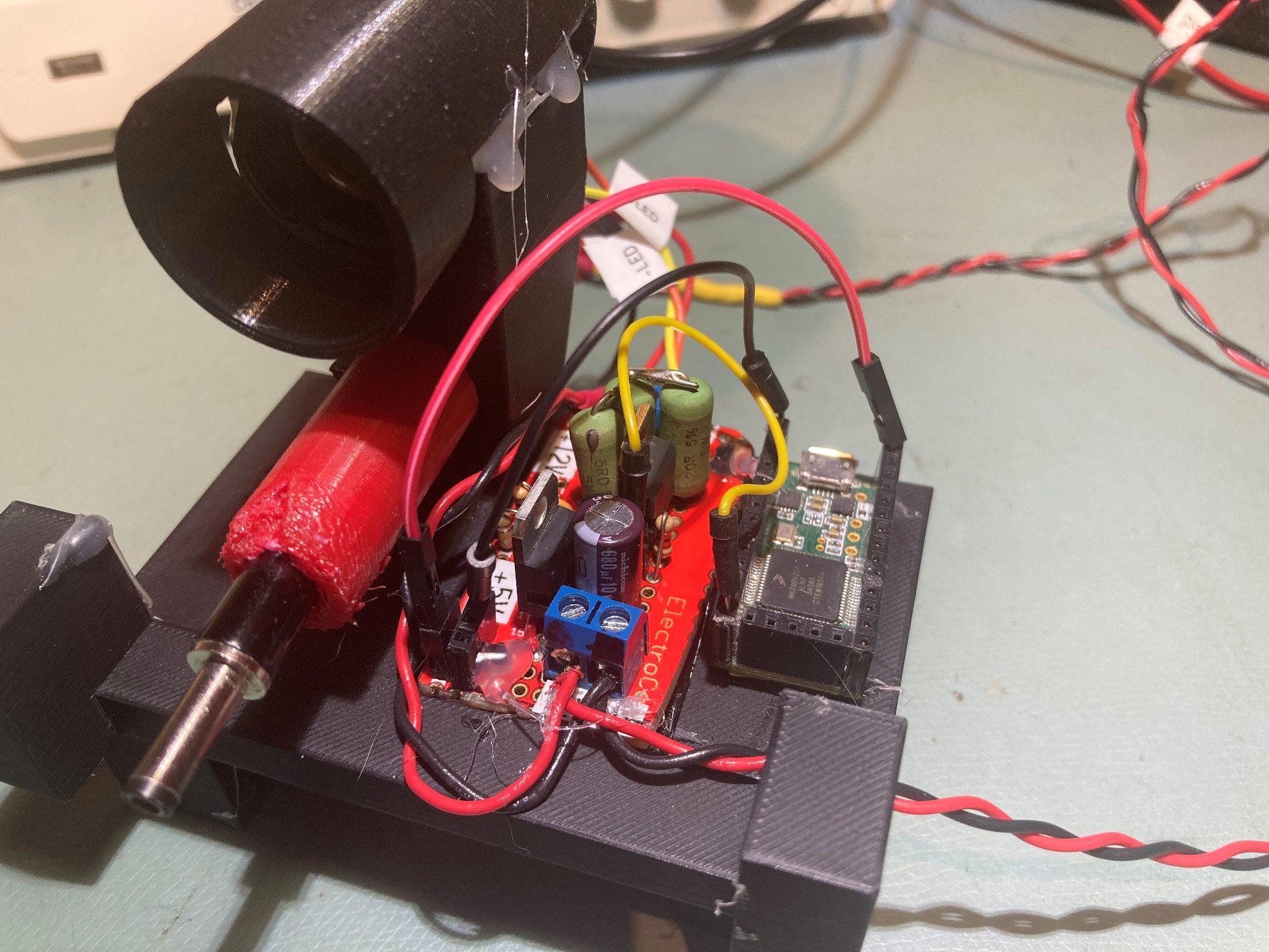
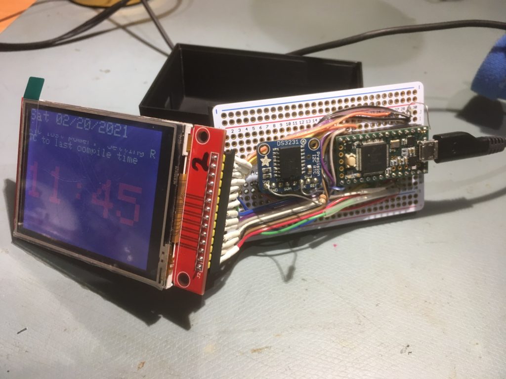
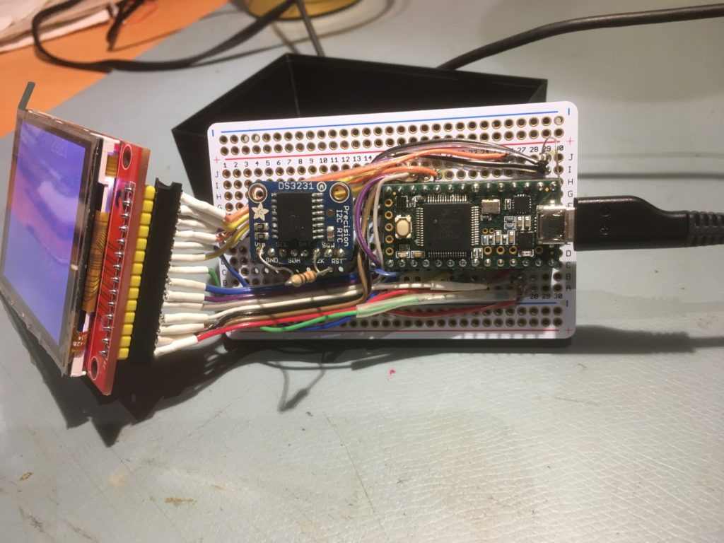
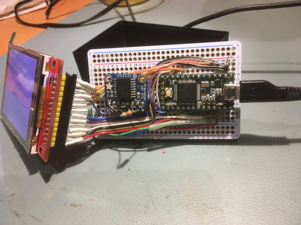
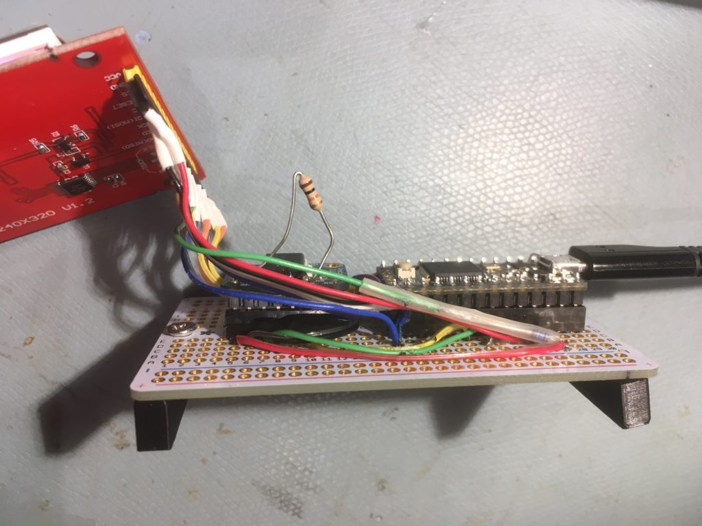
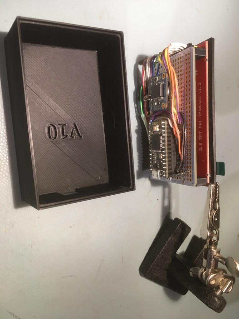
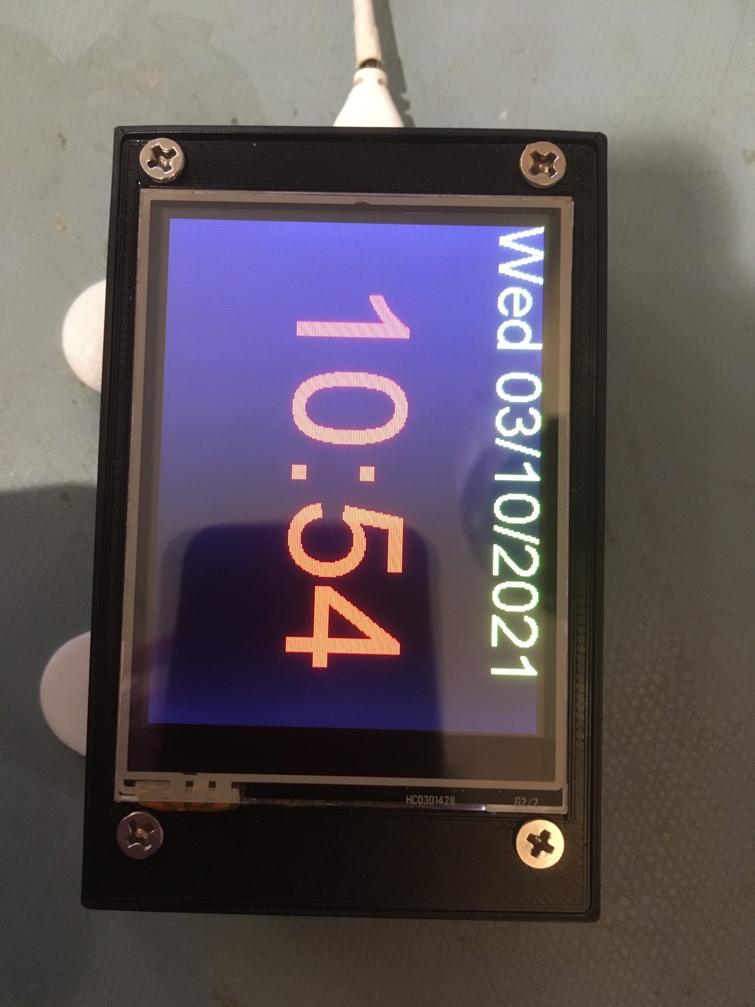
Once I got everything working (well, except for the touch screen stuff that I plan to add later), I fabricated a nice box using Open SCAD and TinkerCad, and made a more permanent version using a half-sized ‘perma-proto’ board, as shown below
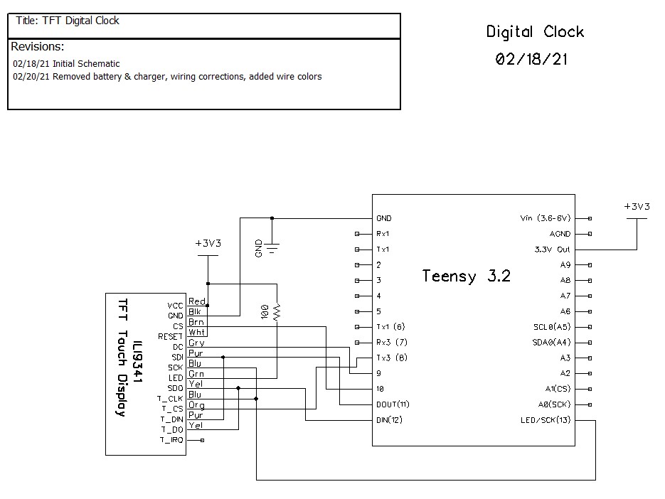
Here’s the more-or-less final schematic
7 March 2021 Update:
After a long and somewhat agonizing journey, I finally got the touch-screen stuff working, so I can now adjust the time on my digital clock using on-screen touch-sensitive controls. Here’s the updated schematic:
The only real difference between this one and the previous schematic is the T_IRQ line is no longer connected; the Teensy-optimized XPT2046_Touchscreen.h/cpp library doesn’t use it.
Here’s a short video showing how the touch-screen enabled time/date adjustment feature works:
Although I hope to clean up this code considerably in the future, I include it here in it’s entirety in it’s current state
|
1 2 3 4 5 6 7 8 9 10 11 12 13 14 15 16 17 18 19 20 21 22 23 24 25 26 27 28 29 30 31 32 33 34 35 36 37 38 39 40 41 42 43 44 45 46 47 48 49 50 51 52 53 54 55 56 57 58 59 60 61 62 63 64 65 66 67 68 69 70 71 72 73 74 75 76 77 78 79 80 81 82 83 84 85 86 87 88 89 90 91 92 93 94 95 96 97 98 99 100 101 102 103 104 105 106 107 108 109 110 111 112 113 114 115 116 117 118 119 120 121 122 123 124 125 126 127 128 129 130 131 132 133 134 135 136 137 138 139 140 141 142 143 144 145 146 147 148 149 150 151 152 153 154 155 156 157 158 159 160 161 162 163 164 165 166 167 168 169 170 171 172 173 174 175 176 177 178 179 180 181 182 183 184 185 186 187 188 189 190 191 192 193 194 195 196 197 198 199 200 201 202 203 204 205 206 207 208 209 210 211 212 213 214 215 216 217 218 219 220 221 222 223 224 225 226 227 228 229 230 231 232 233 234 235 236 237 238 239 240 241 242 243 244 245 246 247 248 249 250 251 252 253 254 255 256 257 258 259 260 261 262 263 264 265 266 267 268 269 270 271 272 273 274 275 276 277 278 279 280 281 282 283 284 285 286 287 288 289 290 291 292 293 294 295 296 297 298 299 300 301 302 303 304 305 306 307 308 309 310 311 312 313 314 315 316 317 318 319 320 321 322 323 324 325 326 327 328 329 330 331 332 333 334 335 336 337 338 339 340 341 342 343 344 345 346 347 348 349 350 351 352 353 354 355 356 357 358 359 360 361 362 363 364 365 366 367 368 369 370 371 372 373 374 375 376 377 378 379 380 381 382 383 384 385 386 387 388 389 390 391 392 393 394 395 396 397 398 399 400 401 402 403 404 405 406 407 408 409 410 411 412 413 414 415 416 417 418 419 420 421 422 423 424 425 426 427 428 429 430 431 432 433 434 435 436 437 438 439 440 441 442 443 444 445 446 447 448 449 450 451 452 453 454 455 456 457 458 459 460 461 462 463 464 465 466 467 468 469 470 471 472 473 474 475 476 477 478 479 480 481 482 483 484 485 486 487 488 489 490 491 492 493 494 495 496 497 498 499 500 501 502 503 504 505 506 507 508 509 510 511 512 513 514 515 516 517 518 519 520 521 522 523 524 525 526 527 528 529 530 531 532 533 534 535 536 537 538 539 540 541 542 543 544 545 546 547 548 549 550 551 552 553 554 555 556 557 558 559 560 561 562 563 564 565 566 567 568 569 570 571 572 573 574 575 576 577 578 579 580 581 582 583 584 585 586 587 588 589 590 591 592 593 594 595 596 597 598 599 600 601 602 603 604 605 606 607 608 609 610 611 612 613 614 615 616 617 618 619 620 621 622 623 624 625 626 627 628 629 630 631 632 633 634 635 636 637 638 639 640 641 642 643 644 645 646 647 648 649 650 651 652 653 654 655 656 657 658 659 660 661 662 663 664 665 666 667 668 669 670 671 672 673 674 675 676 677 678 679 680 681 682 683 684 685 686 687 688 689 690 691 692 693 694 695 696 697 698 699 700 701 702 703 704 705 706 707 708 709 710 711 712 713 714 715 716 717 718 719 720 721 722 723 724 725 726 727 728 729 730 731 732 733 734 735 736 737 738 739 740 741 742 743 744 745 746 747 748 749 750 751 752 753 754 755 756 757 758 759 760 761 762 763 764 765 766 767 768 769 770 771 772 773 774 775 776 777 778 779 780 781 782 783 784 785 786 787 788 789 790 791 792 793 794 795 796 797 798 799 800 801 802 803 804 805 806 807 808 809 810 811 812 813 814 815 816 817 818 819 820 821 822 823 824 825 826 827 828 829 830 831 832 833 834 835 836 837 838 839 840 841 842 843 844 845 846 847 848 849 850 851 852 853 854 855 856 857 858 859 860 861 862 |
/* Name: Teensy_LCDClockV3.ino Created: 3/2/2021 1:37:22 PM Author: FRANKNEWXPS15\Frank This version adds date/time adjustment using touch screen */ #include <XPT2046_Touchscreen.h> #include <ILI9341_t3n.h> #include <Wire.h> #include "RTClib.h" #include "elapsedMillis.h" #include "CustomBox.h" #define N0_DIAGNOSTICS //**************************************************************************** // Settings and objects //**************************************************************************** #pragma region DISPLAY_PIN_ASSIGNMENTS //02/15/21 pin assignments from https://www.pjrc.com/store/display_ili9341_touch.html #define TFT_DC 9 #define TFT_CS 10 #define TFT_RST 7 #define TFT_SCK 13 #define TFT_MISO 12 #define TFT_MOSI 11 #define TOUCH_CS 8 #pragma endregion DISPLAY_PIN_ASSIGNMENTS XPT2046_Touchscreen ts(TOUCH_CS); ILI9341_t3n tft = ILI9341_t3n(TFT_CS, TFT_DC, TFT_RST, TFT_MOSI, TFT_SCK, TFT_MISO); elapsedMillis mSecSinceLastClockUpdate; const int CLOCK_UPDATE_MSEC = 1000; #pragma region DISP_AND_ADJ_BOX_PARAMETERS // Size of the color selection boxes and the paintbrush size #define MAX_DISPLAY_X 240 #define MAX_DISPLAY_Y 320 #define SCREEN_ORIENTATION_1 #define TS_MINX 600 #define TS_MINY 600 #define TS_MAXX 3758 #define TS_MAXY 3612 const int PLUSBOX_X = 20; const int PLUSBOX_Y = 180; const int PLUSBOX_WIDTH = 50; const int PLUSBOX_HEIGHT = 50; const int PLUSBOX_COLOR = ILI9341_BLUE; const int MINUSBOX_X = 120; const int MINUSBOX_Y = 180; const int MINUSBOX_WIDTH = 50; const int MINUSBOX_HEIGHT = 50; const int MINUSBOX_COLOR = ILI9341_YELLOW; const String nextstr = "NEXT"; const int nextstr_width = 70; const int nextstr_height = 20; const int NEXTBOX_X = 220; const int NEXTBOX_Y = 180; const int NEXTBOX_COLOR = ILI9341_GREEN; const int NEXTBOX_WIDTH = 100; const int NEXTBOX_HEIGHT = 50; const int TIME_BOX_X = 0; const int TIME_BOX_Y = 98; const int TIME_BOX_WIDTH = 350; const int TIME_BOX_HEIGHT = 74; const int DATE_BOX_X = 0; const int DATE_BOX_Y = 0; const int DATE_BOX_WIDTH = 320; const int DATE_BOX_HEIGHT = 30; //03/05/21 used to hide adjustment boxes const int ALL_ADJ_BOXES_WIDTH = NEXTBOX_X + NEXTBOX_WIDTH; const int ALL_ADJ_BOXES_HEIGHT = 50; const int TIME_HIGHLIGHT_BOX_WIDTH = 75; const int TIME_HIGHLIGHT_BOX_HEIGHT = 5; const int TIME_HIGHLIGHT_BOX_YLOC = 90; const int ALL_TIME_HIGHLIGHT_BOX_WIDTH = ALL_ADJ_BOXES_WIDTH; const int DATE_HIGHLIGHT_BOX_WIDTH = 35; const int DATE_HIGHLIGHT_BOX_HEIGHT = 5; const int DATE_HIGHLIGHT_BOX_YLOC = 30; const int ALL_DATE_HIGHLIGHT_BOX_WIDTH = ALL_ADJ_BOXES_WIDTH; CustomBox PlusBox(PLUSBOX_X, PLUSBOX_Y, PLUSBOX_WIDTH, PLUSBOX_HEIGHT, PLUSBOX_COLOR); CustomBox MinusBox(MINUSBOX_X, MINUSBOX_Y, MINUSBOX_WIDTH, MINUSBOX_HEIGHT, MINUSBOX_COLOR); CustomBox NextBox(NEXTBOX_X, NEXTBOX_Y, NEXTBOX_WIDTH, NEXTBOX_HEIGHT, NEXTBOX_COLOR); CustomBox HourHighlightBox(0, TIME_HIGHLIGHT_BOX_YLOC, TIME_HIGHLIGHT_BOX_WIDTH, TIME_HIGHLIGHT_BOX_HEIGHT, ILI9341_WHITE); CustomBox MinuteHighlightBox(100, TIME_HIGHLIGHT_BOX_YLOC, TIME_HIGHLIGHT_BOX_WIDTH, TIME_HIGHLIGHT_BOX_HEIGHT, ILI9341_WHITE); CustomBox SecondHighlightBox(210, TIME_HIGHLIGHT_BOX_YLOC, TIME_HIGHLIGHT_BOX_WIDTH, TIME_HIGHLIGHT_BOX_HEIGHT, ILI9341_WHITE); CustomBox MonthHighlightBox(70, DATE_HIGHLIGHT_BOX_YLOC, DATE_HIGHLIGHT_BOX_WIDTH, DATE_HIGHLIGHT_BOX_HEIGHT, ILI9341_WHITE); CustomBox DayHighlightBox(120, DATE_HIGHLIGHT_BOX_YLOC, DATE_HIGHLIGHT_BOX_WIDTH, DATE_HIGHLIGHT_BOX_HEIGHT, ILI9341_WHITE); CustomBox YearHighlightBox(180, DATE_HIGHLIGHT_BOX_YLOC, 2*DATE_HIGHLIGHT_BOX_WIDTH, DATE_HIGHLIGHT_BOX_HEIGHT, ILI9341_WHITE); CustomBox TimeBox(TIME_BOX_X, TIME_BOX_Y, TIME_BOX_WIDTH, TIME_BOX_HEIGHT, ILI9341_BLACK); CustomBox DateBox(DATE_BOX_X, DATE_BOX_Y, DATE_BOX_WIDTH, DATE_BOX_HEIGHT, ILI9341_BLACK); enum AdjustmentState { ADJ_NONE = 0, ADJ_HOUR, ADJ_MIN, ADJ_SEC, ADJ_DAYOFWEEK, ADJ_MONTH, ADJ_DAY, ADJ_YEAR }; int aDaysInMonth[] = { 31,28,31,30,31,30,31,31,30,31,30,31 }; AdjustmentState CurAdjState = ADJ_NONE; const int TOUCH_TIMEOUT_MSEC = 5000; //reverts to regular display if no further touch input elapsedMillis mSecSinceLastTouch; //timer for touch timout #pragma endregion Display & Adj Box Parameters #pragma region RTC Support #define FORCE_RTC_TO_LAST_COMPILE_TIME //uncomment to manually set RTC to last compile time RTC_DS3231 rtc; char daysOfTheWeek[7][12] = { "Sun", "Mon", "Tue", "Wed", "Thu", "Fri", "Sat" }; DateTime now, lastTime; char buffer[100]; int lasthour = 0; //02/15/21 added to refresh screen on the hour struct tStamp { unsigned long mSec; byte RTC_Status; }; #define DS3231_ADDRESS 0x68 ///< I2C address for DS3231 #define DS3231_STATUSREG 0x0F ///< Status register #define RTCStatArraySize 10 #define RTCStatTime_IntervalMsec 100 tStamp RTCStatArray[RTCStatArraySize]; #pragma endregion RTC Support void setup() { Serial.begin(9600); delay(3000); Serial.println("Teensy 3.2 TFT Clock Program"); #pragma region DISPLAY INITIALIZATION Serial.println("Initializing TFT display"); tft.begin(); // Note: you can now set the SPI speed to any value // the default value is 30Mhz, but most ILI9341 displays // can handle at least 60Mhz and as much as 100Mhz // tft.setClock(60000000); tft.fillScreen(ILI9341_BLACK); tft.setTextColor(ILI9341_YELLOW); tft.setTextSize(2); tft.setRotation(1); #pragma endregion region DISPLAY INITIALIZATION #pragma region TFT DIAGNOSTICS #ifndef N0_DIAGNOSTICS // read diagnostics (optional but can help debug problems) uint8_t x = tft.readcommand8(ILI9341_RDMODE); Serial.print("Display Power Mode: 0x"); Serial.println(x, HEX); x = tft.readcommand8(ILI9341_RDMADCTL); Serial.print("MADCTL Mode: 0x"); Serial.println(x, HEX); x = tft.readcommand8(ILI9341_RDPIXFMT); Serial.print("Pixel Format: 0x"); Serial.println(x, HEX); x = tft.readcommand8(ILI9341_RDIMGFMT); Serial.print("Image Format: 0x"); Serial.println(x, HEX); x = tft.readcommand8(ILI9341_RDSELFDIAG); Serial.print("Self Diagnostic: 0x"); Serial.println(x, HEX); Serial.println(F("Benchmark Time (microseconds)")); Serial.print(F("Screen fill ")); Serial.println(testFillScreen()); delay(200); Serial.print(F("Text ")); Serial.println(testText()); delay(600); Serial.print(F("Proportional Text ")); Serial.println(testProportionalText()); delay(600); Serial.print(F("Lines ")); Serial.println(testLines(ILI9341_CYAN)); delay(200); Serial.print(F("Horiz/Vert Lines ")); Serial.println(testFastLines(ILI9341_RED, ILI9341_BLUE)); delay(200); Serial.print(F("Rectangles (outline) ")); Serial.println(testRects(ILI9341_GREEN)); delay(200); Serial.print(F("Rectangles (filled) ")); Serial.println(testFilledRects(ILI9341_YELLOW, ILI9341_MAGENTA)); delay(200); Serial.print(F("Circles (filled) ")); Serial.println(testFilledCircles(10, ILI9341_MAGENTA)); Serial.print(F("Circles (outline) ")); Serial.println(testCircles(10, ILI9341_WHITE)); delay(200); Serial.print(F("Triangles (outline) ")); Serial.println(testTriangles()); delay(200); Serial.print(F("Triangles (filled) ")); Serial.println(testFilledTriangles()); delay(200); Serial.print(F("Rounded rects (outline) ")); Serial.println(testRoundRects()); delay(200); Serial.print(F("Rounded rects (filled) ")); Serial.println(testFilledRoundRects()); delay(200); Serial.println(F("Done!")); #endif // !N0_DIAGNOSTICS #pragma endregion region TFT DIAGNOSTICS #pragma region RTC_SETUP DateBox.Draw(&tft); //erase previous text tft.setCursor(0, 0); Serial.println("Initializing RTC..."); tft.println("Initializing RTC..."); delay(1000); if (!rtc.begin()) { DateBox.Draw(&tft); //erase previous text tft.setCursor(0, 0); Serial.println("Couldn't find RTC"); tft.println("Couldn't find RTC"); while (1); } bool lp = rtc.lostPower(); Serial.print("lostPower() reports "); Serial.println(lp); DateBox.Draw(&tft); //erase previous text tft.setCursor(0, 0); tft.printf("lostPower() = %d\n", lp); delay(1000); if (rtc.lostPower()) { Serial.println("RTC lost power. Setting RTC to last compile time"); DateBox.Draw(&tft); //erase previous text tft.setCursor(0, 0); tft.println("RTC lost power. Setting RTC to last compile time"); // following line sets the RTC to the date & time this sketch was compiled rtc.adjust(DateTime(F(__DATE__), F(__TIME__))); } #ifdef FORCE_RTC_TO_LAST_COMPILE_TIME Serial.println("Forcing RTC to last compile time"); // following line sets the RTC to the date & time this sketch was compiled rtc.adjust(DateTime(F(__DATE__), F(__TIME__))); #endif // //DateTime now = rtc.now(); now = rtc.now(); //char buffer[100]; memset(buffer, '\0', 100); GetDayDateTimeStringFromDateTime(now, buffer); Serial.println("Retrieving Date/Time from RTC...."); Serial.print("Date String = "); Serial.println(buffer); #pragma endregion RTC_SETUP //DEBUG!! //tft.println("Setting time to just before midnight"); //rtc.adjust(DateTime(2021, 02, 13, 00, 59, 45)); //DEBUG!! //02/15/21 needed detect hour changes for screen refresh now = rtc.now(); lasthour = now.hour(); mSecSinceLastClockUpdate = 0; //used to space out clock updates in loop() } void loop(void) { //Serial.printf("%lu: mSecSinceLastClockUpdate = %lu\n", millis(), (long int)mSecSinceLastClockUpdate); delay(100); //see if there is a touch anywhere if (ts.touched()) { mSecSinceLastTouch = 0; //reset the timeout watchdog while (mSecSinceLastTouch < TOUCH_TIMEOUT_MSEC) { //Serial.printf("mSecSinceLastTouch = %lu\n", (unsigned long int)mSecSinceLastTouch); TS_Point Tp = ts.getPoint();// Retrieve the touch point if (Tp.z > 1000) { mSecSinceLastTouch = 0; //reset the timeout watchdog TS_Point Dp = GetTouchPointInDisplayCoords(Tp); CurAdjState = (AdjustmentState)AdjustTimeAndDate(Dp); //Serial.printf("Tp.z = %d: AdjustTimeAndDate(%d, %d) returns %d\n", Tp.z, Dp.x, Dp.y, (int)CurAdjState); if (CurAdjState > ADJ_NONE) { ShowLongTimeDisplay(); ShowAdjButtons(); } } } HideButtons(); HideHighlightBars(); ShowNormalTimeDisplay(); ShowDateDisplay(); CurAdjState = ADJ_NONE; mSecSinceLastClockUpdate = 0; } if (mSecSinceLastClockUpdate > CLOCK_UPDATE_MSEC) { mSecSinceLastClockUpdate -= CLOCK_UPDATE_MSEC; now = rtc.now(); ShowDateDisplay(); //Display day and date //Display time if (CurAdjState > ADJ_NONE) { ShowLongTimeDisplay(); } else { ShowNormalTimeDisplay(); } } } #pragma region DATE_TIME_FUNCTIONS void GetDayDateTimeStringFromDateTime(DateTime dt, char* bufptr) { int mydayofweek = dt.dayOfTheWeek(); //mydayofweek = (mydayofweek < 0) ? 0 : mydayofweek; //guard for return of 0 from weekday() int myday = dt.day(); int mymonth = dt.month(); int myyear = dt.year(); int myhour = dt.hour(); int mymin = dt.minute(); int mysec = dt.second(); char* dayofweek = (char*)daysOfTheWeek[mydayofweek]; sprintf(bufptr, "%s %4d/%02d/%02d at %02d:%02d:%02d", dayofweek, mymonth, myday, myyear, myhour, mymin, mysec); } void HourStringFromDateTime(DateTime dt, char* bufptr) { int hourval = dt.hour(); if (hourval > 12) { hourval -= 12; } //sprintf(bufptr, "%02d", hourval); sprintf(bufptr, "%d", hourval); } void MinuteStringFromDateTime(DateTime dt, char* bufptr) { sprintf(bufptr, "%02d", dt.minute()); } #pragma endregion DATE_TIME_FUNCTIONS AdjustmentState AdjustTimeAndDate(TS_Point Dp) { AdjustmentState adjstate = ADJ_NONE; DateTime newtime; DateTime now = rtc.now(); //int new_hour, new_minute, new_month, new_day, new_year; int new_hour, new_minute, new_month, new_day; //Serial.printf("In GetCurAdjState with CurAdjState = %d, at point (%d,%d)\n", CurAdjState, Dp.x, Dp.y); switch (CurAdjState) { case ADJ_NONE: if (TimeBox.TouchHit(Dp.x, Dp.y)) { adjstate = ADJ_HOUR; //always start with hour ShowHighlightBar(ADJ_HOUR); } else if (DateBox.TouchHit(Dp.x, Dp.y)) { adjstate = ADJ_MONTH; //always start with month ShowHighlightBar(ADJ_MONTH); } break; case ADJ_HOUR: Serial.print("In GetCurAdjState ADJ_HOUR case\n"); adjstate = ADJ_HOUR; if (PlusBox.TouchHit(Dp.x, Dp.y)) { Serial.printf("Plus box touch at (%d,%d)\n", Dp.x, Dp.y); Serial.printf("Old time is %d/%d/%d %d:%d\n", now.month(), now.day(), now.year(), now.hour(), now.minute()); new_hour = now.hour() + 1; if (new_hour >= 24) { new_hour -= 24; } newtime = DateTime(now.year(), now.month(), now.day(), new_hour, now.minute(), now.second()); Serial.printf("New time is %d/%d/%d %d:%d\n", newtime.month(), newtime.day(), newtime.year(), newtime.hour(), newtime.minute()); rtc.adjust(newtime); now = rtc.now(); Serial.printf("RTC now set to %d/%d/%d %d:%d\n", now.day(), now.month(), now.year(), now.hour(), now.minute()); ShowLongTimeDisplay(); delay(500); //delay for a while to avoid multiple 'add' operations } else if (MinusBox.TouchHit(Dp.x, Dp.y)) { Serial.printf("Minus box touch at (%d,%d)\n", Dp.x, Dp.y); Serial.printf("Old time is %d/%d/%d %d:%d\n", now.month(), now.day(), now.year(), now.hour(), now.minute()); new_hour = now.hour() - 1; if (new_hour < 0) { new_hour += 24; } newtime = DateTime(now.year(), now.month(), now.day(), new_hour, now.minute(), now.second()); Serial.printf("New time is %d/%d/%d %d:%d\n", newtime.month(), newtime.day(), newtime.year(), newtime.hour(), newtime.minute()); rtc.adjust(newtime); now = rtc.now(); Serial.printf("RTC now set to %d/%d/%d %d:%d\n", now.day(), now.month(), now.year(), now.hour(), now.minute()); ShowLongTimeDisplay(); delay(500); //delay for a while to avoid multiple 'add' operations } else if (NextBox.TouchHit(Dp.x, Dp.y)) { //Serial.printf("Next box touch at (%d,%d)\n", Dp.x, Dp.y); adjstate = ADJ_MIN; ShowHighlightBar(ADJ_MIN); delay(500); //prevent multiple NEXT transitions } break; case ADJ_MIN: Serial.print("In GetCurAdjState ADJ_MIN case\n"); adjstate = ADJ_MIN; if (PlusBox.TouchHit(Dp.x, Dp.y)) { Serial.printf("Plus box touch at (%d,%d)\n", Dp.x, Dp.y); Serial.printf("Old time is %d/%d/%d %d:%d\n", now.month(), now.day(), now.year(), now.hour(), now.minute()); new_minute = now.minute() + 1; if (new_minute >= 60) { new_minute = 0; } newtime = DateTime(now.year(), now.month(), now.day(), now.hour(), new_minute, now.second()); Serial.printf("New time is %d/%d/%d %d:%d\n", newtime.month(), newtime.day(), newtime.year(), newtime.hour(), newtime.minute()); rtc.adjust(newtime); now = rtc.now(); Serial.printf("RTC now set to %d/%d/%d %d:%d\n", now.day(), now.month(), now.year(), now.hour(), now.minute()); ShowLongTimeDisplay(); delay(500); //delay for a while to avoid multiple 'add' operations } else if (MinusBox.TouchHit(Dp.x, Dp.y)) { Serial.printf("Minus box touch at (%d,%d)\n", Dp.x, Dp.y); newtime = DateTime(now.year(), now.month(), now.day(), now.hour(), now.minute() - 1); Serial.printf("ADJ_HOUR case in DoMinusOp(). Decrementing Hour Value\n"); Serial.printf("Old time is %d:%d:%d:%d\n", now.day(), now.month(), now.year(), now.hour()); Serial.printf("New time is %d:%d:%d:%d\n", newtime.day(), newtime.month(), newtime.year(), newtime.hour()); rtc.adjust(newtime); Serial.printf("RTC now set to %d:%d:%d:%d\n", now.day(), now.month(), now.year(), now.hour()); ShowLongTimeDisplay(); delay(500); //delay for a while to avoid multiple 'add' operations } else if (NextBox.TouchHit(Dp.x, Dp.y)) { //Serial.printf("Next box touch at (%d,%d)\n", Dp.x, Dp.y); adjstate = ADJ_SEC; ShowHighlightBar(ADJ_SEC); delay(500); //prevent multiple NEXT transitions } break; case ADJ_SEC: Serial.print("In GetCurAdjState ADJ_SEC case\n"); adjstate = ADJ_SEC; if (PlusBox.TouchHit(Dp.x, Dp.y)) { Serial.printf("Plus box touch at (%d,%d)\n", Dp.x, Dp.y); Serial.printf("Old time is %d/%d/%d %d:%d:%d\n", now.month(), now.day(), now.year(), now.hour(), now.minute(), now.second()); newtime = DateTime(now.year(), now.month(), now.day(), now.hour(), now.minute(), 0); Serial.printf("New time is %d/%d/%d %d:%d:%d\n", newtime.month(), newtime.day(), newtime.year(), newtime.hour(), newtime.minute(), newtime.second()); rtc.adjust(newtime); now = rtc.now(); Serial.printf("RTC now set to %d/%d/%d %d:%d:%d\n", now.day(), now.month(), now.year(), now.hour(), now.minute(), now.second()); ShowLongTimeDisplay(); delay(500); //delay for a while to avoid multiple 'add' operations } else if (MinusBox.TouchHit(Dp.x, Dp.y)) { Serial.printf("Minus box touch at (%d,%d)\n", Dp.x, Dp.y); Serial.printf("Old time is %d/%d/%d %d:%d:%d\n", now.month(), now.day(), now.year(), now.hour(), now.minute(), now.second()); newtime = DateTime(now.year(), now.month(), now.day(), now.hour(), now.minute(), 0); Serial.printf("New time is %d/%d/%d %d:%d:%d\n", newtime.month(), newtime.day(), newtime.year(), newtime.hour(), newtime.minute(), newtime.second()); rtc.adjust(newtime); now = rtc.now(); Serial.printf("RTC now set to %d/%d/%d %d:%d:%d\n", now.day(), now.month(), now.year(), now.hour(), now.minute(), now.second()); ShowLongTimeDisplay(); delay(500); //delay for a while to avoid multiple 'add' operations } else if (NextBox.TouchHit(Dp.x, Dp.y)) { //Serial.printf("Next box touch at (%d,%d)\n", Dp.x, Dp.y); adjstate = ADJ_HOUR; ShowHighlightBar(ADJ_HOUR); delay(500); //prevent multiple NEXT transitions } break; case ADJ_DAYOFWEEK: break; case ADJ_MONTH: Serial.print("In GetCurAdjState ADJ_MONTH case\n"); adjstate = ADJ_MONTH; if (PlusBox.TouchHit(Dp.x, Dp.y)) { Serial.printf("Plus box touch at (%d,%d)\n", Dp.x, Dp.y); Serial.printf("Old time is %d/%d/%d %d:%d\n", now.month(), now.day(), now.year(), now.hour(), now.minute()); new_month = now.month() + 1; if (new_month > 12) { new_month -= 12; } newtime = DateTime(now.year(), new_month, now.day(), now.hour(), now.minute(), now.second()); Serial.printf("New time is %d/%d/%d %d:%d\n", newtime.month(), newtime.day(), newtime.year(), newtime.hour(), newtime.minute()); rtc.adjust(newtime); now = rtc.now(); Serial.printf("RTC now set to %d/%d/%d %d:%d\n", now.month(), now.day(), now.year(), now.hour(), now.minute()); ShowDateDisplay(); delay(500); //delay for a while to avoid multiple 'add' operations } else if (MinusBox.TouchHit(Dp.x, Dp.y)) { Serial.printf("Minus box touch at (%d,%d)\n", Dp.x, Dp.y); Serial.printf("Old time is %d/%d/%d %d:%d\n", now.month(), now.day(), now.year(), now.hour(), now.minute()); new_month = now.month() - 1; new_month = (new_month <= 0) ? 12 : new_month; newtime = DateTime(now.year(), new_month, now.day(), now.hour(), now.minute(), now.second()); Serial.printf("New time is %d/%d/%d %d:%d\n", newtime.month(), newtime.day(), newtime.year(), newtime.hour(), newtime.minute()); rtc.adjust(newtime); now = rtc.now(); Serial.printf("RTC now set to %d/%d/%d %d:%d\n", now.day(), now.month(), now.year(), now.hour(), now.minute()); ShowDateDisplay(); delay(500); //delay for a while to avoid multiple 'add' operations } else if (NextBox.TouchHit(Dp.x, Dp.y)) { //Serial.printf("Next box touch at (%d,%d)\n", Dp.x, Dp.y); adjstate = ADJ_DAY; ShowHighlightBar(ADJ_DAY); delay(500); //prevent multiple NEXT transitions } break; case ADJ_DAY: Serial.print("In GetCurAdjState ADJ_DAY case\n"); adjstate = ADJ_DAY; if (PlusBox.TouchHit(Dp.x, Dp.y)) { Serial.printf("Plus box touch at (%d,%d)\n", Dp.x, Dp.y); Serial.printf("Old time is %d/%d/%d %d:%d\n", now.month(), now.day(), now.year(), now.hour(), now.minute()); new_day = AdjustDayValue(now.month(), now.day() + 1); //not all months have same number of days newtime = DateTime(now.year(), now.month(), new_day, now.hour(), now.minute(), now.second()); Serial.printf("New time is %d/%d/%d %d:%d\n", newtime.month(), newtime.day(), newtime.year(), newtime.hour(), newtime.minute()); rtc.adjust(newtime); now = rtc.now(); Serial.printf("RTC now set to %d/%d/%d %d:%d\n", now.day(), now.month(), now.year(), now.hour(), now.minute()); ShowDateDisplay(); delay(500); //delay for a while to avoid multiple 'add' operations } else if (MinusBox.TouchHit(Dp.x, Dp.y)) { Serial.printf("Minus box touch at (%d,%d)\n", Dp.x, Dp.y); Serial.printf("Old time is %d/%d/%d %d:%d\n", now.month(), now.day(), now.year(), now.hour(), now.minute()); new_day = now.day() - 1; new_day = (new_day <= 0) ? aDaysInMonth[now.month() - 1] : new_day; newtime = DateTime(now.year(), now.month(), new_day, now.hour(), now.minute(), now.second()); Serial.printf("New time is %d/%d/%d %d:%d\n", newtime.month(), newtime.day(), newtime.year(), newtime.hour(), newtime.minute()); rtc.adjust(newtime); now = rtc.now(); Serial.printf("RTC now set to %d/%d/%d %d:%d\n", now.day(), now.month(), now.year(), now.hour(), now.minute()); ShowDateDisplay(); delay(500); //delay for a while to avoid multiple 'add' operations } else if (NextBox.TouchHit(Dp.x, Dp.y)) { //Serial.printf("Next box touch at (%d,%d)\n", Dp.x, Dp.y); adjstate = ADJ_YEAR; ShowHighlightBar(ADJ_YEAR); delay(500); //prevent multiple NEXT transitions } break; case ADJ_YEAR: Serial.print("In GetCurAdjState ADJ_YEAR case\n"); adjstate = ADJ_YEAR; if (PlusBox.TouchHit(Dp.x, Dp.y)) { Serial.printf("Plus box touch at (%d,%d)\n", Dp.x, Dp.y); Serial.printf("Old time is %d/%d/%d %d:%d\n", now.month(), now.day(), now.year(), now.hour(), now.minute()); newtime = DateTime(now.year() + 1, now.month(), now.day(), now.hour(), now.minute(), now.second()); Serial.printf("New time is %d/%d/%d %d:%d\n", newtime.month(), newtime.day(), newtime.year(), newtime.hour(), newtime.minute()); rtc.adjust(newtime); now = rtc.now(); Serial.printf("RTC now set to %d/%d/%d %d:%d\n", now.month(), now.day(), now.year(), now.hour(), now.minute()); ShowDateDisplay(); delay(500); //delay for a while to avoid multiple 'add' operations } else if (MinusBox.TouchHit(Dp.x, Dp.y)) { Serial.printf("Minus box touch at (%d,%d)\n", Dp.x, Dp.y); Serial.printf("Old time is %d/%d/%d %d:%d\n", now.month(), now.day(), now.year(), now.hour(), now.minute()); newtime = DateTime(now.year() - 1, now.month(), now.day(), now.hour(), now.minute(), now.second()); Serial.printf("New time is %d/%d/%d %d:%d\n", newtime.month(), newtime.day(), newtime.year(), newtime.hour(), newtime.minute()); rtc.adjust(newtime); now = rtc.now(); Serial.printf("RTC now set to %d/%d/%d %d:%d\n", now.day(), now.month(), now.year(), now.hour(), now.minute()); ShowDateDisplay(); delay(500); //delay for a while to avoid multiple 'add' operations } else if (NextBox.TouchHit(Dp.x, Dp.y)) { //Serial.printf("Next box touch at (%d,%d)\n", Dp.x, Dp.y); adjstate = ADJ_MONTH; ShowHighlightBar(ADJ_MONTH); delay(500); //prevent multiple NEXT transitions } break; default: break; } //Serial.printf("AdjustTimeAndDate(%d, %d) returns %d\n", Dp.x, Dp.y, (int)adjstate); return adjstate ; } #pragma region Helper Functions TS_Point GetTouchPointInDisplayCoords(TS_Point Tp) { //Purpose: Retrieve a touch point in display coordinate system //Inputs: // Rotation value // Mapping values // TS_Point from touch chip //Outputs: // TS_Point object containing touch (X,Y) in display coordinates //Plan: // Step1: Retrieve touch point from touch chip // Step2: Map to display coordinates taking rotation into account //Step1: Retrieve touch point from touch chip //TS_Point Tp = ts.getPoint(); TS_Point Dp; //Step2: Map to display coordinates taking rotation into account #ifdef SCREEN_ORIENTATION_1 Dp.x = map(Tp.x, TS_MAXX, TS_MINX, 0, tft.width()); Dp.y = map(Tp.y, TS_MAXY, TS_MINY, 0, tft.height()); #else #endif ////DEBUG!! //Serial.printf(" GetTouchPointInDisplayCoords: %lu\t%d\t%d\t%d\t%d\t%d\n", // millis(), Tp.x, Tp.y, Tp.z, Dp.x, Dp.y); ////DEBUG!! return Dp; } void ShowAdjButtons() { PlusBox.Draw(&tft, '+', ILI9341_BLACK); MinusBox.Draw(&tft, '-', ILI9341_BLACK); //03/04/21 getTextBounds() reports wrong info - use 70w x 20 tall int txt_x = NEXTBOX_X + round((float)(NEXTBOX_WIDTH / 2.)) - round((float)(70 / 2.)); int txt_y = NEXTBOX_Y + round((float)(NEXTBOX_HEIGHT / 2.)) - round((float)(20 / 2.)); tft.setCursor(txt_x, txt_y); tft.setTextSize(3); tft.setTextColor(ILI9341_BLACK); String boxstr = "NEXT"; NextBox.Draw(&tft); tft.print(boxstr); } void HideButtons() { PlusBox.Draw(&tft, ILI9341_BLACK); MinusBox.Draw(&tft, ILI9341_BLACK); NextBox.Draw(&tft, ILI9341_BLACK); } void ShowNormalTimeDisplay() { //Serial.printf("In ShowNormalTimeDisplay\n"); now = rtc.now(); tft.setCursor(0, 100); tft.setTextColor(ILI9341_RED); tft.setTextSize(10); TimeBox.Draw(&tft); tft.setCursor(0, 100); int hournum = now.hour(); //guard against 1259->1300 && 2359->0000 transitions if (hournum > 12) { hournum -= 12; } else if (hournum == 0) { hournum += 12; } hournum = (hournum > 12) ? hournum - 12 : hournum; tft.printf("%2d:%02d", hournum, now.minute()); } void ShowLongTimeDisplay() { //Serial.printf("In ShowLongTimeDisplay\n"); now = rtc.now(); tft.setCursor(0, 100); tft.setTextColor(ILI9341_RED); //tft.setTextSize(10); tft.setTextSize(6); tft.fillRect(0, 98, 350, 74, ILI9341_BLACK); //tft.fillRect(0, 98, 350, 74, ILI9341_YELLOW); tft.setCursor(0, 100); int hournum = now.hour(); //guard against 1259->1300 && 2359->0000 transitions if (hournum > 12) { hournum -= 12; } else if (hournum == 0) { hournum += 12; } hournum = (hournum > 12) ? hournum - 12 : hournum; tft.printf("%2d:%02d:%02d", hournum, now.minute(), now.second()); } void ShowHighlightBar(AdjustmentState adjstate) { switch (adjstate) { case ADJ_NONE: Serial.printf("ADJ_NONE case in ShowHighlightBox()\n"); HideHighlightBars(); break; case ADJ_HOUR: HideHighlightBars(); HourHighlightBox.Draw(&tft); break; case ADJ_MIN: HideHighlightBars(); MinuteHighlightBox.Draw(&tft); break; case ADJ_SEC: HideHighlightBars(); SecondHighlightBox.Draw(&tft); break; case ADJ_DAYOFWEEK: break; case ADJ_MONTH: HideHighlightBars(); MonthHighlightBox.Draw(&tft); break; case ADJ_DAY: HideHighlightBars(); DayHighlightBox.Draw(&tft); break; case ADJ_YEAR: HideHighlightBars(); YearHighlightBox.Draw(&tft); break; default: break; } } void HideHighlightBars() { tft.fillRect(0, DATE_HIGHLIGHT_BOX_YLOC, ALL_DATE_HIGHLIGHT_BOX_WIDTH, DATE_HIGHLIGHT_BOX_HEIGHT, ILI9341_BLACK); tft.fillRect(0, TIME_HIGHLIGHT_BOX_YLOC, ALL_TIME_HIGHLIGHT_BOX_WIDTH, TIME_HIGHLIGHT_BOX_HEIGHT, ILI9341_BLACK); } void ShowDateDisplay() { DateTime now = rtc.now(); DateBox.Draw(&tft); tft.setTextColor(ILI9341_YELLOW); tft.setCursor(0, 0); tft.setTextSize(3); tft.printf("%s %02d/%02d/%02d\n", daysOfTheWeek[now.dayOfTheWeek()], now.month(), now.day(), now.year()); } int AdjustDayValue(int month, int day) { if (day > aDaysInMonth[month-1]) { Serial.printf("%d is greater than max days (%d) for this month - setting to 1\n", day, aDaysInMonth[month-1] ); return 1; } else { return day; } } #pragma endregion Helper Functions |
|
1 2 3 4 5 6 7 8 9 10 11 12 13 14 15 16 17 18 19 20 21 22 23 24 25 26 27 28 29 30 31 32 33 34 35 36 37 38 39 40 41 42 43 44 45 46 47 48 49 50 51 52 53 54 55 56 57 58 59 60 61 62 63 64 65 66 67 68 69 70 71 72 73 74 75 76 77 78 79 80 81 82 83 84 85 86 87 88 89 90 91 92 93 94 95 96 97 98 99 100 101 102 103 104 105 106 107 108 109 110 111 112 113 114 115 116 117 118 119 120 |
#pragma once #ifndef _ILI9341_t3NH_ #include <ILI9341_t3n.h> #endif // !_ILI9341_t3NH_ class CustomBox { public: int x; int y; private: int w; int h; int color; public: CustomBox(int in_x, int in_y, int in_w, int in_h, int in_color); CustomBox(int in_w, int in_h, int in_color); void Draw(ILI9341_t3n* disp); void Draw(ILI9341_t3n* disp, char c, int txtcolor, int size); void Draw(ILI9341_t3n* disp, String txt, int size); void Draw(ILI9341_t3n* disp, char* buff, int size); void Draw(ILI9341_t3n* disp, int color); bool TouchHit(int in_x, int in_y); }; CustomBox::CustomBox(int in_w, int in_h, int in_color) { x = 0; y = 0; w = in_w; h = in_h; color = in_color; } CustomBox::CustomBox(int in_x, int in_y, int in_w, int in_h, int in_color) { x = in_x; y = in_y; w = in_w; h = in_h; color = in_color; } inline void CustomBox::Draw(ILI9341_t3n* disp) { disp->fillRect(x, y, w, h, color); } //class CustomBoxWithText :CustomBox //{ //private: // char boxtext[6]; //public: // CustomBoxWithText(int in_x, int in_y, int in_w, int in_h, int in_color, char* txt); //}; // // //CustomBox::CustomBox(int in_x, int in_y, int in_w, int in_h, int in_color) //{ // x = in_x; // y = in_y; // w = in_w; // h = in_h; // color = in_color; //} inline void CustomBox::Draw(ILI9341_t3n* disp, char c, int txtcolor, int size = 0) { disp->fillRect(x, y, w, h, color); if (size==0) { size = round((float)h / 10.); } int char_x = x + round((float)w / 4.); //int char_x = x; disp->setCursor(char_x, y+size); disp->setTextSize(size); disp->setTextColor(txtcolor); disp->print(c); } inline void CustomBox::Draw(ILI9341_t3n* disp, String txt, int size) { disp->fillRect(x, y, w, h, color); disp->setCursor(x, y); disp->setTextSize(size); disp->print(txt); } inline void CustomBox::Draw(ILI9341_t3n* disp, char* buff, int size) { Serial.printf("In Draw() with buff = %s\n", buff); disp->fillRect(x, y, w, h, color); //disp->setCursor(x, y); disp->setTextSize(size); //disp->setTextDatum(MC_DATUM); disp->drawString1(buff, strlen(buff), x, y); } inline void CustomBox::Draw(ILI9341_t3n* disp, int newcolor) { disp->fillRect(x, y, w, h, newcolor); } inline bool CustomBox::TouchHit(int in_x, int in_y) { //Purpose: Determine if input coordinates are within a specified box //Inputs: // in_x, in_y = integers denoting mapped touch coordinates // box location & dimensions //Outputs: // true if (in_x, in_y) falls within box region. Othewise, false //Serial.printf("TouchHit(%d,%d), box (x,y,w,h) = (%d,%d,%d,%d)\n", // in_x, in_y, x, y, w, h); return (in_x > x && in_y > y && in_x < x + w && in_y < y + h); } |
10 March 2021 Update:
After getting all of the above to work, I decided to re-tackle the proportional fonts issue. In my first attempt, I had used the ‘ILI9341_t3’ version of the ILI9341 Teensy library, and there is a newer ‘ILI9341_t3n‘ version out now. So, I modified one of the example programs (unfortunately still written for the old library) to be compatible and got proportional fonts (well, just the Arial one) working on the display.
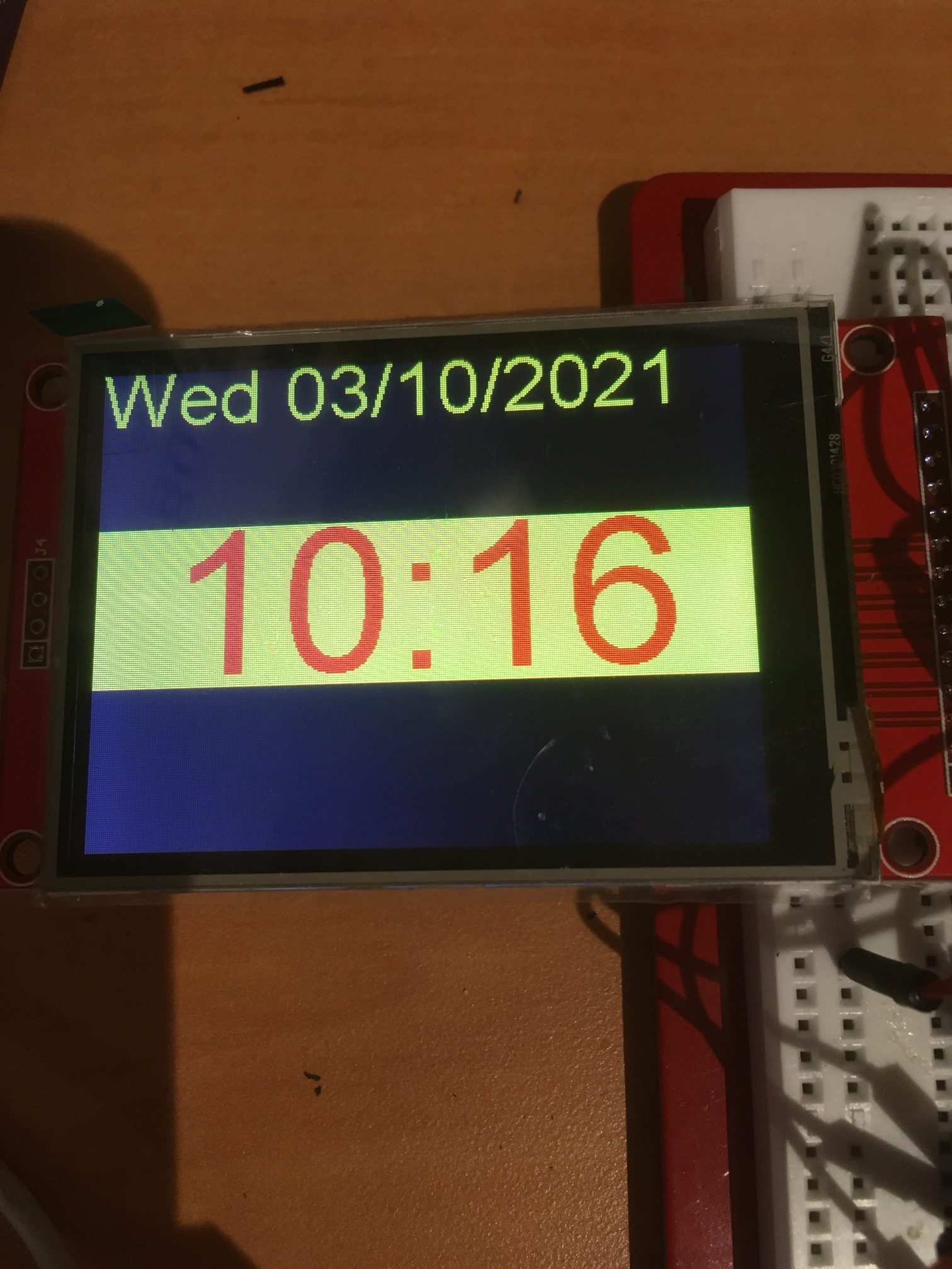
After several hours of running this example with no apparent artifacts or problems, I decided to update my complete clock program to use the Arial font. After making the modifications and running it overnight, the time & date displays were still rock-solid the next day, as shown in the following photo – YAY!!
So now all that is left to do is to upload the new Arial-based code (with the time background color switched back to ‘black’) to my ‘working’ clock module, sit back and enjoy the proportional font display.
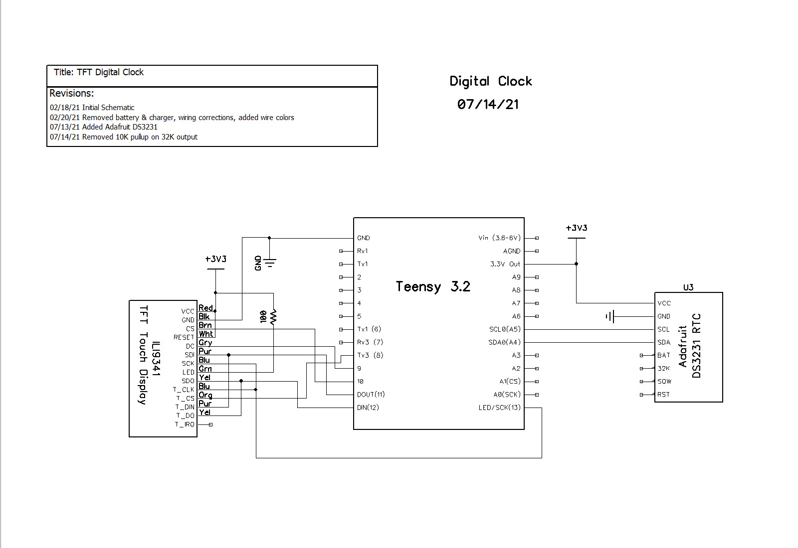
14 July 2021 Update:
I noticed that my clock had some ‘issues’ with time/date adjustments, so I ‘put it back in the shop’ for some additional TLC. While I was at it, I noticed that the system schematic didn’t include the DS3231 (hard to have a clock without a RTC!), so I updated it as well. Here’s the updated schematic.
The updates made were to make the time/date adjustments more robust. The updated code is included in its entirety below. First the main program:
|
1 2 3 4 5 6 7 8 9 10 11 12 13 14 15 16 17 18 19 20 21 22 23 24 25 26 27 28 29 30 31 32 33 34 35 36 37 38 39 40 41 42 43 44 45 46 47 48 49 50 51 52 53 54 55 56 57 58 59 60 61 62 63 64 65 66 67 68 69 70 71 72 73 74 75 76 77 78 79 80 81 82 83 84 85 86 87 88 89 90 91 92 93 94 95 96 97 98 99 100 101 102 103 104 105 106 107 108 109 110 111 112 113 114 115 116 117 118 119 120 121 122 123 124 125 126 127 128 129 130 131 132 133 134 135 136 137 138 139 140 141 142 143 144 145 146 147 148 149 150 151 152 153 154 155 156 157 158 159 160 161 162 163 164 165 166 167 168 169 170 171 172 173 174 175 176 177 178 179 180 181 182 183 184 185 186 187 188 189 190 191 192 193 194 195 196 197 198 199 200 201 202 203 204 205 206 207 208 209 210 211 212 213 214 215 216 217 218 219 220 221 222 223 224 225 226 227 228 229 230 231 232 233 234 235 236 237 238 239 240 241 242 243 244 245 246 247 248 249 250 251 252 253 254 255 256 257 258 259 260 261 262 263 264 265 266 267 268 269 270 271 272 273 274 275 276 277 278 279 280 281 282 283 284 285 286 287 288 289 290 291 292 293 294 295 296 297 298 299 300 301 302 303 304 305 306 307 308 309 310 311 312 313 314 315 316 317 318 319 320 321 322 323 324 325 326 327 328 329 330 331 332 333 334 335 336 337 338 339 340 341 342 343 344 345 346 347 348 349 350 351 352 353 354 355 356 357 358 359 360 361 362 363 364 365 366 367 368 369 370 371 372 373 374 375 376 377 378 379 380 381 382 383 384 385 386 387 388 389 390 391 392 393 394 395 396 397 398 399 400 401 402 403 404 405 406 407 408 409 410 411 412 413 414 415 416 417 418 419 420 421 422 423 424 425 426 427 428 429 430 431 432 433 434 435 436 437 438 439 440 441 442 443 444 445 446 447 448 449 450 451 452 453 454 455 456 457 458 459 460 461 462 463 464 465 466 467 468 469 470 471 472 473 474 475 476 477 478 479 480 481 482 483 484 485 486 487 488 489 490 491 492 493 494 495 496 497 498 499 500 501 502 503 504 505 506 507 508 509 510 511 512 513 514 515 516 517 518 519 520 521 522 523 524 525 526 527 528 529 530 531 532 533 534 535 536 537 538 539 540 541 542 543 544 545 546 547 548 549 550 551 552 553 554 555 556 557 558 559 560 561 562 563 564 565 566 567 568 569 570 571 572 573 574 575 576 577 578 579 580 581 582 583 584 585 586 587 588 589 590 591 592 593 594 595 596 597 598 599 600 601 602 603 604 605 606 607 608 609 610 611 612 613 614 615 616 617 618 619 620 621 622 623 624 625 626 627 628 629 630 631 632 633 634 635 636 637 638 639 640 641 642 643 644 645 646 647 648 649 650 651 652 653 654 655 656 657 658 659 660 661 662 663 664 665 666 667 668 669 670 671 672 673 674 675 676 677 678 679 680 681 682 683 684 685 686 687 688 689 690 691 692 693 694 695 696 697 698 699 700 701 702 703 704 705 706 707 708 709 710 711 712 713 714 715 716 717 718 719 720 721 722 723 724 725 726 727 728 729 730 731 732 733 734 735 736 737 738 739 740 741 742 743 744 745 746 747 748 749 750 751 752 753 754 755 756 757 758 759 760 761 762 763 764 765 766 767 768 769 770 771 772 773 774 775 776 777 778 779 780 781 782 783 784 785 786 787 788 789 790 791 792 793 794 795 796 797 798 799 800 801 802 803 804 805 806 807 808 809 810 811 812 813 814 815 816 817 818 819 820 821 822 823 824 825 826 827 828 829 830 831 832 833 834 835 836 837 838 839 840 841 842 843 844 845 846 847 848 849 850 851 852 853 854 855 856 857 858 859 860 861 862 863 864 865 866 867 868 869 870 871 872 873 874 875 876 877 878 879 880 881 882 883 884 885 886 887 888 889 890 891 892 893 894 895 896 897 898 899 900 901 902 903 904 905 906 907 |
/* Name: Teensy_LCDClockV4.ino Created: 3/9/2021 11:12:31 AM Author: FRANKNEWXPS15\Frank This project was cloned from Teensy_LCDClockV3 to re-investigate the use of proportional fonts */ #include <XPT2046_Touchscreen.h> #include <ILI9341_t3n.h> #include <Wire.h> #include "RTClib.h" #include "elapsedMillis.h" #include "CustomBox.h" #include "ili9341_t3n_font_Arial.h" #define N0_DIAGNOSTICS //**************************************************************************** // Settings and objects //**************************************************************************** #pragma region DISPLAY_PIN_ASSIGNMENTS //02/15/21 pin assignments from https://www.pjrc.com/store/display_ili9341_touch.html #define TFT_DC 9 #define TFT_CS 10 #define TFT_RST 7 #define TFT_SCK 13 #define TFT_MISO 12 #define TFT_MOSI 11 #define TOUCH_CS 8 #pragma endregion DISPLAY_PIN_ASSIGNMENTS XPT2046_Touchscreen ts(TOUCH_CS); ILI9341_t3n tft = ILI9341_t3n(TFT_CS, TFT_DC, TFT_RST, TFT_MOSI, TFT_SCK, TFT_MISO); elapsedMillis mSecSinceLastClockUpdate; const int CLOCK_UPDATE_MSEC = 1000; #pragma region DISP_AND_ADJ_BOX_PARAMETERS // Size of the color selection boxes and the paintbrush size #define MAX_DISPLAY_X 240 #define MAX_DISPLAY_Y 320 #define SCREEN_ORIENTATION_1 #define TS_MINX 600 #define TS_MINY 600 #define TS_MAXX 3758 #define TS_MAXY 3612 const int PLUSBOX_X = 20; const int PLUSBOX_Y = 180; const int PLUSBOX_WIDTH = 50; const int PLUSBOX_HEIGHT = 50; const int PLUSBOX_COLOR = ILI9341_BLUE; const int MINUSBOX_X = 120; const int MINUSBOX_Y = 180; const int MINUSBOX_WIDTH = 50; const int MINUSBOX_HEIGHT = 50; const int MINUSBOX_COLOR = ILI9341_YELLOW; const String nextstr = "NEXT"; const int nextstr_width = 70; const int nextstr_height = 20; const int NEXTBOX_X = 220; const int NEXTBOX_Y = 180; const int NEXTBOX_COLOR = ILI9341_GREEN; const int NEXTBOX_WIDTH = 100; const int NEXTBOX_HEIGHT = 50; const int TIME_BOX_X = 0; const int TIME_BOX_Y = 82; const int TIME_BOX_WIDTH = 350; const int TIME_BOX_HEIGHT = 80; const int DATE_BOX_X = 0; const int DATE_BOX_Y = 0; const int DATE_BOX_WIDTH = 320; const int DATE_BOX_HEIGHT = 30; //03/05/21 used to hide adjustment boxes const int ALL_ADJ_BOXES_WIDTH = NEXTBOX_X + NEXTBOX_WIDTH; const int ALL_ADJ_BOXES_HEIGHT = 50; const int TIME_HIGHLIGHT_BOX_WIDTH = 75; const int TIME_HIGHLIGHT_BOX_HEIGHT = 5; const int TIME_HIGHLIGHT_BOX_YLOC = 75; const int ALL_TIME_HIGHLIGHT_BOX_WIDTH = ALL_ADJ_BOXES_WIDTH; const int DATE_HIGHLIGHT_BOX_WIDTH = 40; const int DATE_HIGHLIGHT_BOX_HEIGHT = 5; const int DATE_HIGHLIGHT_BOX_YLOC = 40; const int ALL_DATE_HIGHLIGHT_BOX_WIDTH = ALL_ADJ_BOXES_WIDTH; CustomBox PlusBox(PLUSBOX_X, PLUSBOX_Y, PLUSBOX_WIDTH, PLUSBOX_HEIGHT, PLUSBOX_COLOR); CustomBox MinusBox(MINUSBOX_X, MINUSBOX_Y, MINUSBOX_WIDTH, MINUSBOX_HEIGHT, MINUSBOX_COLOR); CustomBox NextBox(NEXTBOX_X, NEXTBOX_Y, NEXTBOX_WIDTH, NEXTBOX_HEIGHT, NEXTBOX_COLOR); CustomBox HourHighlightBox(20, TIME_HIGHLIGHT_BOX_YLOC, TIME_HIGHLIGHT_BOX_WIDTH, TIME_HIGHLIGHT_BOX_HEIGHT, ILI9341_WHITE); CustomBox MinuteHighlightBox(120, TIME_HIGHLIGHT_BOX_YLOC, TIME_HIGHLIGHT_BOX_WIDTH, TIME_HIGHLIGHT_BOX_HEIGHT, ILI9341_WHITE); CustomBox SecondHighlightBox(230, TIME_HIGHLIGHT_BOX_YLOC, TIME_HIGHLIGHT_BOX_WIDTH, TIME_HIGHLIGHT_BOX_HEIGHT, ILI9341_WHITE); CustomBox MonthHighlightBox(72, DATE_HIGHLIGHT_BOX_YLOC, DATE_HIGHLIGHT_BOX_WIDTH, DATE_HIGHLIGHT_BOX_HEIGHT, ILI9341_WHITE); CustomBox DayHighlightBox(132, DATE_HIGHLIGHT_BOX_YLOC, DATE_HIGHLIGHT_BOX_WIDTH, DATE_HIGHLIGHT_BOX_HEIGHT, ILI9341_WHITE); CustomBox YearHighlightBox(178, DATE_HIGHLIGHT_BOX_YLOC, 90, DATE_HIGHLIGHT_BOX_HEIGHT, ILI9341_WHITE); CustomBox TimeBox(TIME_BOX_X, TIME_BOX_Y, TIME_BOX_WIDTH, TIME_BOX_HEIGHT, ILI9341_BLACK); CustomBox DateBox(DATE_BOX_X, DATE_BOX_Y, DATE_BOX_WIDTH, DATE_BOX_HEIGHT, ILI9341_BLACK); enum AdjustmentState { ADJ_NONE = 0, ADJ_HOUR, ADJ_MIN, ADJ_SEC, ADJ_DAYOFWEEK, ADJ_MONTH, ADJ_DAY, ADJ_YEAR }; const char AdjValNameArray[8][9] = { "ADJ_NONE", "ADJ_HOUR", "ADJ_MIN", "ADJ_SEC", "ADJ_DOW", "ADJ_MNTH", "ADJ_DAY", "ADJ_YEAR" }; int aDaysInMonth[] = { 31,28,31,30,31,30,31,31,30,31,30,31 }; AdjustmentState CurAdjState = ADJ_NONE; const int TOUCH_TIMEOUT_MSEC = 5000; //reverts to regular display if no further touch input elapsedMillis mSecSinceLastTouch; //timer for touch timout #pragma endregion Display & Adj Box Parameters #pragma region RTC Support #define FORCE_RTC_TO_LAST_COMPILE_TIME //uncomment to manually set RTC to last compile time RTC_DS3231 rtc; char daysOfTheWeek[7][12] = { "Sun", "Mon", "Tue", "Wed", "Thu", "Fri", "Sat" }; DateTime now, lastTime; char buffer[100]; int lasthour = 0; //02/15/21 added to refresh screen on the hour struct tStamp { unsigned long mSec; byte RTC_Status; }; #define DS3231_ADDRESS 0x68 ///< I2C address for DS3231 #define DS3231_STATUSREG 0x0F ///< Status register #define RTCStatArraySize 10 #define RTCStatTime_IntervalMsec 100 tStamp RTCStatArray[RTCStatArraySize]; #pragma endregion RTC Support void setup() { Serial.begin(9600); delay(3000); Serial.println("Teensy 3.2 TFT Clock Program"); #pragma region DISPLAY INITIALIZATION Serial.println("Initializing TFT display"); tft.begin(); // Note: you can now set the SPI speed to any value // the default value is 30Mhz, but most ILI9341 displays // can handle at least 60Mhz and as much as 100Mhz // tft.setClock(60000000); tft.fillScreen(ILI9341_BLACK); tft.setTextColor(ILI9341_YELLOW); tft.setTextSize(2); tft.setRotation(1); #pragma endregion region DISPLAY INITIALIZATION #pragma region TFT DIAGNOSTICS #ifndef N0_DIAGNOSTICS // read diagnostics (optional but can help debug problems) uint8_t x = tft.readcommand8(ILI9341_RDMODE); Serial.print("Display Power Mode: 0x"); Serial.println(x, HEX); x = tft.readcommand8(ILI9341_RDMADCTL); Serial.print("MADCTL Mode: 0x"); Serial.println(x, HEX); x = tft.readcommand8(ILI9341_RDPIXFMT); Serial.print("Pixel Format: 0x"); Serial.println(x, HEX); x = tft.readcommand8(ILI9341_RDIMGFMT); Serial.print("Image Format: 0x"); Serial.println(x, HEX); x = tft.readcommand8(ILI9341_RDSELFDIAG); Serial.print("Self Diagnostic: 0x"); Serial.println(x, HEX); Serial.println(F("Benchmark Time (microseconds)")); Serial.print(F("Screen fill ")); Serial.println(testFillScreen()); delay(200); Serial.print(F("Text ")); Serial.println(testText()); delay(600); Serial.print(F("Proportional Text ")); Serial.println(testProportionalText()); delay(600); Serial.print(F("Lines ")); Serial.println(testLines(ILI9341_CYAN)); delay(200); Serial.print(F("Horiz/Vert Lines ")); Serial.println(testFastLines(ILI9341_RED, ILI9341_BLUE)); delay(200); Serial.print(F("Rectangles (outline) ")); Serial.println(testRects(ILI9341_GREEN)); delay(200); Serial.print(F("Rectangles (filled) ")); Serial.println(testFilledRects(ILI9341_YELLOW, ILI9341_MAGENTA)); delay(200); Serial.print(F("Circles (filled) ")); Serial.println(testFilledCircles(10, ILI9341_MAGENTA)); Serial.print(F("Circles (outline) ")); Serial.println(testCircles(10, ILI9341_WHITE)); delay(200); Serial.print(F("Triangles (outline) ")); Serial.println(testTriangles()); delay(200); Serial.print(F("Triangles (filled) ")); Serial.println(testFilledTriangles()); delay(200); Serial.print(F("Rounded rects (outline) ")); Serial.println(testRoundRects()); delay(200); Serial.print(F("Rounded rects (filled) ")); Serial.println(testFilledRoundRects()); delay(200); Serial.println(F("Done!")); #endif // !N0_DIAGNOSTICS #pragma endregion region TFT DIAGNOSTICS #pragma region RTC_SETUP DateBox.Draw(&tft); //erase previous text tft.setCursor(0, 0); Serial.println("Initializing RTC..."); //tft.println("Initializing RTC..."); delay(1000); if (!rtc.begin()) { DateBox.Draw(&tft); //erase previous text tft.setCursor(0, 0); Serial.println("Couldn't find RTC"); tft.println("Couldn't find RTC"); while (1); } bool lp = rtc.lostPower(); Serial.print("lostPower() reports "); Serial.println(lp); DateBox.Draw(&tft); //erase previous text tft.setCursor(0, 0); tft.printf("lostPower() = %d\n", lp); delay(1000); if (rtc.lostPower()) { Serial.println("RTC lost power. Setting RTC to last compile time"); DateBox.Draw(&tft); //erase previous text tft.setCursor(0, 0); tft.println("RTC lost power. Setting RTC to last compile time"); // following line sets the RTC to the date & time this sketch was compiled rtc.adjust(DateTime(F(__DATE__), F(__TIME__))); } #ifdef FORCE_RTC_TO_LAST_COMPILE_TIME Serial.println("Forcing RTC to last compile time"); // following line sets the RTC to the date & time this sketch was compiled rtc.adjust(DateTime(F(__DATE__), F(__TIME__))); #endif // //DateTime now = rtc.now(); now = rtc.now(); memset(buffer, '\0', 100); GetDayDateTimeStringFromDateTime(now, buffer); Serial.println("Retrieving Date/Time from RTC...."); Serial.print("Date String = "); Serial.println(buffer); #pragma endregion RTC_SETUP //DEBUG!! //tft.println("Setting time to just before midnight"); //rtc.adjust(DateTime(2021, 02, 13, 00, 59, 45)); //DEBUG!! //02/15/21 needed detect hour changes for screen refresh now = rtc.now(); lasthour = now.hour(); mSecSinceLastClockUpdate = 0; //used to space out clock updates in loop() } void loop(void) { //Serial.printf("%lu: mSecSinceLastClockUpdate = %lu\n", millis(), (long int)mSecSinceLastClockUpdate); delay(100); //see if there is a touch anywhere if (ts.touched()) { mSecSinceLastTouch = 0; //reset the timeout watchdog while (mSecSinceLastTouch < TOUCH_TIMEOUT_MSEC) { //Serial.printf("mSecSinceLastTouch = %lu\n", (unsigned long int)mSecSinceLastTouch); TS_Point Tp = ts.getPoint();// Retrieve the touch point if (Tp.z > 1000) { mSecSinceLastTouch = 0; //reset the timeout watchdog TS_Point Dp = GetTouchPointInDisplayCoords(Tp); CurAdjState = (AdjustmentState)AdjustTimeAndDate(Dp); Serial.printf("Tp.z = %d: AdjustTimeAndDate(%d, %d) returns %s\n", Tp.z, Dp.x, Dp.y, AdjValNameArray[(int)CurAdjState]); if (CurAdjState > ADJ_NONE) { ShowLongTimeDisplay(); ShowAdjButtons(); } } } HideButtons(); HideHighlightBars(); ShowNormalTimeDisplay(); ShowDateDisplay(); CurAdjState = ADJ_NONE; mSecSinceLastClockUpdate = 0; } if (mSecSinceLastClockUpdate > CLOCK_UPDATE_MSEC) { mSecSinceLastClockUpdate -= CLOCK_UPDATE_MSEC; now = rtc.now(); ShowDateDisplay(); //Display day and date //Display time if (CurAdjState > ADJ_NONE) { ShowLongTimeDisplay(); } else { ShowNormalTimeDisplay(); } } } #pragma region DATE_TIME_FUNCTIONS void GetDayDateTimeStringFromDateTime(DateTime dt, char* bufptr) { int mydayofweek = dt.dayOfTheWeek(); //mydayofweek = (mydayofweek < 0) ? 0 : mydayofweek; //guard for return of 0 from weekday() int myday = dt.day(); int mymonth = dt.month(); int myyear = dt.year(); int myhour = dt.hour(); int mymin = dt.minute(); int mysec = dt.second(); char* dayofweek = (char*)daysOfTheWeek[mydayofweek]; sprintf(bufptr, "%s %4d/%02d/%02d at %02d:%02d:%02d", dayofweek, mymonth, myday, myyear, myhour, mymin, mysec); } void HourStringFromDateTime(DateTime dt, char* bufptr) { int hourval = dt.hour(); if (hourval > 12) { hourval -= 12; } //sprintf(bufptr, "%02d", hourval); sprintf(bufptr, "%d", hourval); } void MinuteStringFromDateTime(DateTime dt, char* bufptr) { sprintf(bufptr, "%02d", dt.minute()); } #pragma endregion DATE_TIME_FUNCTIONS AdjustmentState AdjustTimeAndDate(TS_Point Dp) { AdjustmentState adjstate = ADJ_NONE; DateTime newtime; DateTime now = rtc.now(); int new_hour = 0; int new_minute = 0; int new_month = 0; int new_day = 0; int cur_day = 0; //added 07/13/21 //Serial.printf("In AdjustTimeAndDate with CurAdjState = %d, at point (%d,%d)\n", CurAdjState, Dp.x, Dp.y); switch (CurAdjState) { case ADJ_NONE: if (TimeBox.TouchHit(Dp.x, Dp.y)) { adjstate = ADJ_HOUR; //always start with hour ShowHighlightBar(ADJ_HOUR); } else if (DateBox.TouchHit(Dp.x, Dp.y)) { adjstate = ADJ_MONTH; //always start with month ShowHighlightBar(ADJ_MONTH); } break; case ADJ_HOUR: Serial.print("In AdjustTimeAndDate ADJ_HOUR case\n"); adjstate = ADJ_HOUR; if (PlusBox.TouchHit(Dp.x, Dp.y)) { Serial.printf("Plus box touch at (%d,%d)\n", Dp.x, Dp.y); Serial.printf("Old time is %d/%d/%d %d:%d\n", now.month(), now.day(), now.year(), now.hour(), now.minute()); new_hour = now.hour() + 1; if (new_hour >= 24) { new_hour -= 24; } newtime = DateTime(now.year(), now.month(), now.day(), new_hour, now.minute(), now.second()); Serial.printf("New time is %d/%d/%d %d:%d\n", newtime.month(), newtime.day(), newtime.year(), newtime.hour(), newtime.minute()); rtc.adjust(newtime); now = rtc.now(); Serial.printf("RTC now set to %d/%d/%d %d:%d\n", now.day(), now.month(), now.year(), now.hour(), now.minute()); ShowLongTimeDisplay(); delay(500); //delay for a while to avoid multiple 'add' operations } else if (MinusBox.TouchHit(Dp.x, Dp.y)) { Serial.printf("Minus box touch at (%d,%d)\n", Dp.x, Dp.y); Serial.printf("Old time is %d/%d/%d %d:%d\n", now.month(), now.day(), now.year(), now.hour(), now.minute()); new_hour = now.hour() - 1; if (new_hour < 0) { new_hour += 24; } newtime = DateTime(now.year(), now.month(), now.day(), new_hour, now.minute(), now.second()); Serial.printf("New time is %d/%d/%d %d:%d\n", newtime.month(), newtime.day(), newtime.year(), newtime.hour(), newtime.minute()); rtc.adjust(newtime); now = rtc.now(); Serial.printf("RTC now set to %d/%d/%d %d:%d\n", now.day(), now.month(), now.year(), now.hour(), now.minute()); ShowLongTimeDisplay(); delay(500); //delay for a while to avoid multiple 'add' operations } else if (NextBox.TouchHit(Dp.x, Dp.y)) { Serial.printf("Next box touch at (%d,%d)\n", Dp.x, Dp.y); adjstate = ADJ_MIN; ShowHighlightBar(ADJ_MIN); delay(500); //prevent multiple NEXT transitions } break; case ADJ_MIN: Serial.print("In AdjustTimeAndDate ADJ_MIN case\n"); adjstate = ADJ_MIN; if (PlusBox.TouchHit(Dp.x, Dp.y)) { Serial.printf("Plus box touch at (%d,%d)\n", Dp.x, Dp.y); Serial.printf("Old time is %d/%d/%d %2d:%2d\n", now.month(), now.day(), now.year(), now.hour(), now.minute()); new_minute = now.minute() + 1; if (new_minute >= 60) { new_minute = 0; } newtime = DateTime(now.year(), now.month(), now.day(), now.hour(), new_minute, now.second()); Serial.printf("New time is %2d:%2d\n", newtime.hour(), newtime.minute()); rtc.adjust(newtime); now = rtc.now(); Serial.printf("RTC now set to %2d:%2d\n", now.day(), now.hour(), now.minute()); ShowLongTimeDisplay(); delay(500); //delay for a while to avoid multiple 'add' operations } else if (MinusBox.TouchHit(Dp.x, Dp.y)) { Serial.printf("Minus box touch at (%d,%d)\n", Dp.x, Dp.y); Serial.printf("ADJ_MIN case in DoMinusOp(). Decrementing Minute Value\n"); Serial.printf("Old time is %2d:%2d\n", now.hour(),now.minute()); new_minute = now.minute() - 1; if (new_minute < 0) { Serial.printf("adjusting for 00/59 rollover\n"); new_minute = 59; } newtime = DateTime(now.year(), now.month(), now.day(), now.hour(), new_minute); rtc.adjust(newtime); now = rtc.now(); Serial.printf("New time is %d:%d\n", now.hour(), now.minute()); Serial.printf("RTC now set to %2d:%2d\n", now.hour(), now.minute()); ShowLongTimeDisplay(); delay(500); //delay for a while to avoid multiple 'decrement' operations } else if (NextBox.TouchHit(Dp.x, Dp.y)) { //Serial.printf("Next box touch at (%d,%d)\n", Dp.x, Dp.y); adjstate = ADJ_SEC; ShowHighlightBar(ADJ_SEC); delay(500); //prevent multiple NEXT transitions } break; case ADJ_SEC: Serial.print("In AdjustTimeAndDate ADJ_SEC case\n"); adjstate = ADJ_SEC; //both PLUS & MINUS operations simply reset seconds to zero if (PlusBox.TouchHit(Dp.x, Dp.y)) { Serial.printf("Plus box touch at (%d,%d)\n", Dp.x, Dp.y); Serial.printf("Old time is %d/%d/%d %d:%d:%d\n", now.month(), now.day(), now.year(), now.hour(), now.minute(), now.second()); newtime = DateTime(now.year(), now.month(), now.day(), now.hour(), now.minute(), 0); Serial.printf("New time is %d/%d/%d %d:%d:%d\n", newtime.month(), newtime.day(), newtime.year(), newtime.hour(), newtime.minute(), newtime.second()); rtc.adjust(newtime); now = rtc.now(); Serial.printf("RTC now set to %d/%d/%d %d:%d:%d\n", now.day(), now.month(), now.year(), now.hour(), now.minute(), now.second()); ShowLongTimeDisplay(); delay(500); //delay for a while to avoid multiple 'add' operations } else if (MinusBox.TouchHit(Dp.x, Dp.y)) { Serial.printf("Minus box touch at (%d,%d)\n", Dp.x, Dp.y); Serial.printf("Old time is %d/%d/%d %d:%d:%d\n", now.month(), now.day(), now.year(), now.hour(), now.minute(), now.second()); newtime = DateTime(now.year(), now.month(), now.day(), now.hour(), now.minute(), 0); Serial.printf("New time is %d/%d/%d %d:%d:%d\n", newtime.month(), newtime.day(), newtime.year(), newtime.hour(), newtime.minute(), newtime.second()); rtc.adjust(newtime); now = rtc.now(); Serial.printf("RTC now set to %d/%d/%d %d:%d:%d\n", now.day(), now.month(), now.year(), now.hour(), now.minute(), now.second()); ShowLongTimeDisplay(); delay(500); //delay for a while to avoid multiple 'add' operations } else if (NextBox.TouchHit(Dp.x, Dp.y)) { //Serial.printf("Next box touch at (%d,%d)\n", Dp.x, Dp.y); adjstate = ADJ_HOUR; ShowHighlightBar(ADJ_HOUR); delay(500); //prevent multiple NEXT transitions } break; case ADJ_DAYOFWEEK: break; case ADJ_MONTH: //07/13/21 rev to watch for next/prev month max days Serial.print("In AdjustTimeAndDate ADJ_MONTH case\n"); adjstate = ADJ_MONTH; if (PlusBox.TouchHit(Dp.x, Dp.y)) { Serial.printf("Plus box touch at (%d,%d)\n", Dp.x, Dp.y); Serial.printf("Old time is %d/%d/%d %d:%d\n", now.month(), now.day(), now.year(), now.hour(), now.minute()); new_month = now.month() + 1; if (new_month > 12) { new_month = 1; //07/13/21 bugfix } //07/13/21 have to adjust if current dayval > max for new month cur_day = now.day(); if (cur_day > aDaysInMonth[new_month - 1]) { Serial.printf("%d Exceeds max days for new month (%d for %d)\n", cur_day, aDaysInMonth[new_month - 1], new_month); new_day = aDaysInMonth[new_month - 1]; } else { new_day = cur_day; } newtime = DateTime(now.year(), new_month, new_day, now.hour(), now.minute(), now.second()); Serial.printf("New time is %d/%d/%d %2d:%2d\n", newtime.month(), newtime.day(), newtime.year(), newtime.hour(), newtime.minute()); rtc.adjust(newtime); now = rtc.now(); Serial.printf("RTC now set to %d/%d/%d %2d:%2d\n", now.month(), now.day(), now.year(), now.hour(), now.minute()); ShowDateDisplay(); delay(500); //delay for a while to avoid multiple 'add' operations } else if (MinusBox.TouchHit(Dp.x, Dp.y)) { Serial.printf("Minus box touch at (%d,%d)\n", Dp.x, Dp.y); Serial.printf("Old time is %d/%d/%d %2d:%2d\n", now.month(), now.day(), now.year(), now.hour(), now.minute()); new_month = now.month() - 1; /*new_month = (new_month <= 0) ? 12 : new_month; */ if (new_month <= 0) { new_month = 12; //no need to check max days, as feb max is 28 and dec max is 31 } else { //have to check max days for new month cur_day = now.day(); if (cur_day > aDaysInMonth[new_month - 1]) { Serial.printf("%d Exceeds max days for new month (%d for %d)\n", cur_day, aDaysInMonth[new_month - 1], new_month); new_day = aDaysInMonth[new_month - 1]; } else new_day = cur_day; } //newtime = DateTime(now.year(), new_month, now.day(), now.hour(), now.minute(), now.second()); newtime = DateTime(now.year(), new_month, new_day, now.hour(), now.minute(), now.second()); Serial.printf("New time is %d/%d/%d %2d:%2d\n", newtime.month(), newtime.day(), newtime.year(), newtime.hour(), newtime.minute()); rtc.adjust(newtime); now = rtc.now(); Serial.printf("RTC now set to %d/%d/%d %2d:%2d\n", now.day(), now.month(), now.year(), now.hour(), now.minute()); ShowDateDisplay(); delay(500); //delay for a while to avoid multiple 'add' operations } else if (NextBox.TouchHit(Dp.x, Dp.y)) { //Serial.printf("Next box touch at (%d,%d)\n", Dp.x, Dp.y); adjstate = ADJ_DAY; ShowHighlightBar(ADJ_DAY); delay(500); //prevent multiple NEXT transitions } break; case ADJ_DAY: Serial.print("In AdjustTimeAndDate ADJ_DAY case\n"); adjstate = ADJ_DAY; if (PlusBox.TouchHit(Dp.x, Dp.y)) { Serial.printf("Plus box touch at (%d,%d)\n", Dp.x, Dp.y); Serial.printf("Old time is %d/%d/%d %2d:%2d\n", now.month(), now.day(), now.year(), now.hour(), now.minute()); new_day = AdjustDayValue(now.month(), now.day() + 1); //not all months have same number of days newtime = DateTime(now.year(), now.month(), new_day, now.hour(), now.minute(), now.second()); Serial.printf("New time is %d/%d/%d %d:%d\n", newtime.month(), newtime.day(), newtime.year(), newtime.hour(), newtime.minute()); rtc.adjust(newtime); now = rtc.now(); Serial.printf("RTC now set to %d/%d/%d %d:%d\n", now.day(), now.month(), now.year(), now.hour(), now.minute()); ShowDateDisplay(); delay(500); //delay for a while to avoid multiple 'add' operations } else if (MinusBox.TouchHit(Dp.x, Dp.y)) { Serial.printf("Minus box touch at (%d,%d)\n", Dp.x, Dp.y); Serial.printf("Old time is %d/%d/%d %d:%d\n", now.month(), now.day(), now.year(), now.hour(), now.minute()); new_day = now.day() - 1; new_day = (new_day <= 0) ? aDaysInMonth[now.month() - 1] : new_day; newtime = DateTime(now.year(), now.month(), new_day, now.hour(), now.minute(), now.second()); Serial.printf("New time is %d/%d/%d %d:%d\n", newtime.month(), newtime.day(), newtime.year(), newtime.hour(), newtime.minute()); rtc.adjust(newtime); now = rtc.now(); Serial.printf("RTC now set to %d/%d/%d %d:%d\n", now.day(), now.month(), now.year(), now.hour(), now.minute()); ShowDateDisplay(); delay(500); //delay for a while to avoid multiple 'add' operations } else if (NextBox.TouchHit(Dp.x, Dp.y)) { //Serial.printf("Next box touch at (%d,%d)\n", Dp.x, Dp.y); adjstate = ADJ_YEAR; ShowHighlightBar(ADJ_YEAR); delay(500); //prevent multiple NEXT transitions } break; case ADJ_YEAR: Serial.print("In AdjustTimeAndDate ADJ_YEAR case\n"); adjstate = ADJ_YEAR; if (PlusBox.TouchHit(Dp.x, Dp.y)) { Serial.printf("Plus box touch at (%d,%d)\n", Dp.x, Dp.y); Serial.printf("Old time is %d/%d/%d %2d:%2d\n", now.month(), now.day(), now.year(), now.hour(), now.minute()); newtime = DateTime(now.year() + 1, now.month(), now.day(), now.hour(), now.minute(), now.second()); Serial.printf("New time is %d/%d/%d %2d:%2d\n", newtime.month(), newtime.day(), newtime.year(), newtime.hour(), newtime.minute()); rtc.adjust(newtime); now = rtc.now(); Serial.printf("RTC now set to %d/%d/%d %2d:%2d\n", now.month(), now.day(), now.year(), now.hour(), now.minute()); ShowDateDisplay(); delay(500); //delay for a while to avoid multiple 'add' operations } else if (MinusBox.TouchHit(Dp.x, Dp.y)) { Serial.printf("Minus box touch at (%d,%d)\n", Dp.x, Dp.y); Serial.printf("Old time is %d/%d/%d %2d:%2d\n", now.month(), now.day(), now.year(), now.hour(), now.minute()); newtime = DateTime(now.year() - 1, now.month(), now.day(), now.hour(), now.minute(), now.second()); Serial.printf("New time is %d/%d/%d %2d:%2d\n", newtime.month(), newtime.day(), newtime.year(), newtime.hour(), newtime.minute()); rtc.adjust(newtime); now = rtc.now(); Serial.printf("RTC now set to %d/%d/%d %d:%d\n", now.day(), now.month(), now.year(), now.hour(), now.minute()); ShowDateDisplay(); delay(500); //delay for a while to avoid multiple 'add' operations } else if (NextBox.TouchHit(Dp.x, Dp.y)) { //Serial.printf("Next box touch at (%d,%d)\n", Dp.x, Dp.y); adjstate = ADJ_MONTH; ShowHighlightBar(ADJ_MONTH); delay(500); //prevent multiple NEXT transitions } break; default: break; } //Serial.printf("AdjustTimeAndDate(%d, %d) returns %d\n", Dp.x, Dp.y, (int)adjstate); return adjstate; } #pragma region Helper Functions TS_Point GetTouchPointInDisplayCoords(TS_Point Tp) { //Purpose: Retrieve a touch point in display coordinate system //Inputs: // Rotation value // Mapping values // TS_Point from touch chip //Outputs: // TS_Point object containing touch (X,Y) in display coordinates //Plan: // Step1: Retrieve touch point from touch chip // Step2: Map to display coordinates taking rotation into account //Step1: Retrieve touch point from touch chip //TS_Point Tp = ts.getPoint(); TS_Point Dp; //Step2: Map to display coordinates taking rotation into account #ifdef SCREEN_ORIENTATION_1 Dp.x = map(Tp.x, TS_MAXX, TS_MINX, 0, tft.width()); Dp.y = map(Tp.y, TS_MAXY, TS_MINY, 0, tft.height()); #else #endif ////DEBUG!! //Serial.printf(" GetTouchPointInDisplayCoords: %lu\t%d\t%d\t%d\t%d\t%d\n", // millis(), Tp.x, Tp.y, Tp.z, Dp.x, Dp.y); ////DEBUG!! return Dp; } void ShowAdjButtons() { Serial.printf("In ShowAdjButtons\n"); HideButtons(); //03/13/21 new centering feature works great! NextBox.Draw(&tft, "NEXT", ILI9341_BLACK, Arial_20, true); PlusBox.Draw(&tft, "+", ILI9341_BLACK, Arial_40, true); MinusBox.Draw(&tft, "-", ILI9341_BLACK, Arial_40, true); } void HideButtons() { PlusBox.Draw(&tft, ILI9341_BLACK); MinusBox.Draw(&tft, ILI9341_BLACK); NextBox.Draw(&tft, ILI9341_BLACK); } void ShowNormalTimeDisplay() { //Serial.printf("In ShowNormalTimeDisplay\n"); now = rtc.now(); int hournum = now.hour(); //guard against 1259->1300 && 2359->0000 transitions if (hournum > 12) { hournum -= 12; } else if (hournum == 0) { hournum += 12; } hournum = (hournum > 12) ? hournum - 12 : hournum; tft.setCursor(0, 100); TimeBox.Draw(&tft); //redraws black background tft.setTextColor(ILI9341_RED); tft.setFont(Arial_72); tft.setCursor(160, 120, true);//try the text centering feature tft.printf("%2d:%02d", hournum, now.minute()); } void ShowLongTimeDisplay() { //Serial.printf("In ShowLongTimeDisplay\n"); now = rtc.now(); tft.setTextColor(ILI9341_RED); tft.setCursor(160, 120, true);//try the text centering feature tft.setFont(Arial_60); TimeBox.Draw(&tft); //redraws black background int hournum = now.hour(); //guard against 1259->1300 && 2359->0000 transitions if (hournum > 12) { hournum -= 12; } else if (hournum == 0) { hournum += 12; } hournum = (hournum > 12) ? hournum - 12 : hournum; tft.printf("%2d:%02d:%02d", hournum, now.minute(), now.second()); } void ShowHighlightBar(AdjustmentState adjstate) { switch (adjstate) { case ADJ_NONE: Serial.printf("ADJ_NONE case in ShowHighlightBox()\n"); HideHighlightBars(); break; case ADJ_HOUR: HideHighlightBars(); HourHighlightBox.Draw(&tft); break; case ADJ_MIN: HideHighlightBars(); MinuteHighlightBox.Draw(&tft); break; case ADJ_SEC: HideHighlightBars(); SecondHighlightBox.Draw(&tft); break; case ADJ_DAYOFWEEK: break; case ADJ_MONTH: HideHighlightBars(); MonthHighlightBox.Draw(&tft); break; case ADJ_DAY: HideHighlightBars(); DayHighlightBox.Draw(&tft); break; case ADJ_YEAR: HideHighlightBars(); YearHighlightBox.Draw(&tft); break; default: break; } } void HideHighlightBars() { tft.fillRect(0, DATE_HIGHLIGHT_BOX_YLOC, ALL_DATE_HIGHLIGHT_BOX_WIDTH, DATE_HIGHLIGHT_BOX_HEIGHT, ILI9341_BLACK); tft.fillRect(0, TIME_HIGHLIGHT_BOX_YLOC, ALL_TIME_HIGHLIGHT_BOX_WIDTH, TIME_HIGHLIGHT_BOX_HEIGHT, ILI9341_BLACK); } void ShowDateDisplay() { DateTime now = rtc.now(); DateBox.Draw(&tft); tft.setTextColor(ILI9341_YELLOW); tft.setCursor(0, 0); //tft.setTextSize(3); tft.setFont(Arial_28); tft.printf("%s %02d/%02d/%02d\n", daysOfTheWeek[now.dayOfTheWeek()], now.month(), now.day(), now.year()); } int AdjustDayValue(int month, int day) { //Notes: // 07/13/21 rev to handle negative day values if (day > aDaysInMonth[month - 1]) { Serial.printf("%d is greater than max days (%d) for this month - setting to 1\n", day, aDaysInMonth[month - 1]); return 1; } //07/13/21 bugfix else if (day <= 0) { int newdaynum = aDaysInMonth[month - 1]; Serial.printf("%d is <= 0: set to max days (%d) for this month\n", day, newdaynum); return newdaynum; } else { return day; } } #pragma endregion Helper Functions |
And then the ‘CustomBox’ class file (no .cpp file – everything is in the .h file)
|
1 2 3 4 5 6 7 8 9 10 11 12 13 14 15 16 17 18 19 20 21 22 23 24 25 26 27 28 29 30 31 32 33 34 35 36 37 38 39 40 41 42 43 44 45 46 47 48 49 50 51 52 53 54 55 56 57 58 59 60 61 62 63 64 65 66 67 68 69 70 71 72 73 74 75 76 77 78 79 80 81 82 83 84 85 86 87 88 89 90 91 92 93 94 95 96 97 98 99 100 101 102 103 104 105 106 107 108 109 110 111 112 113 114 115 116 117 118 119 120 121 122 123 124 125 126 127 128 129 130 131 132 133 134 135 136 137 138 139 140 141 142 143 144 145 146 147 148 149 150 151 152 153 154 155 156 157 158 159 160 |
#pragma once #ifndef _ILI9341_t3NH_ #include <ILI9341_t3n.h> #endif // !_ILI9341_t3NH_ class CustomBox { public: int x; int y; private: int w; int h; int color; public: CustomBox(int in_x, int in_y, int in_w, int in_h, int in_color); CustomBox(int in_w, int in_h, int in_color); void Draw(ILI9341_t3n* disp); void Draw(ILI9341_t3n* disp, char c, int txtcolor, int size); void Draw(ILI9341_t3n* disp, char c, int txtcolor, ILI9341_t3_font_t font, bool centered = false); void Draw(ILI9341_t3n* disp, String txt, int txtcolor, ILI9341_t3_font_t font, bool centered = false); void Draw(ILI9341_t3n* disp, String txt, int size); void Draw(ILI9341_t3n* disp, char* buff, int size); void Draw(ILI9341_t3n* disp, int color); bool TouchHit(int in_x, int in_y); }; CustomBox::CustomBox(int in_w, int in_h, int in_color) { x = 0; y = 0; w = in_w; h = in_h; color = in_color; } CustomBox::CustomBox(int in_x, int in_y, int in_w, int in_h, int in_color) { x = in_x; y = in_y; w = in_w; h = in_h; color = in_color; } inline void CustomBox::Draw(ILI9341_t3n* disp) { disp->fillRect(x, y, w, h, color); } inline void CustomBox::Draw(ILI9341_t3n* disp, char c, int txtcolor, ILI9341_t3_font_t font, bool centered) { int txt_x = x; int txt_y = y; disp->setFont(font); if (centered) { txt_x = x + round((float)(w / 2.)); txt_y = y + round((float)(h / 2.)); } Serial.printf("txt cursor set to (%d,%d)\n", txt_x, txt_y); disp->fillRect(x, y, w, h, color); disp->setTextColor(txtcolor); disp->setCursor(txt_x, txt_y, centered); disp->print(c); } inline void CustomBox::Draw(ILI9341_t3n* disp, String txt, int txtcolor, ILI9341_t3_font_t font, bool centered) { int txt_x = x; int txt_y = y; disp->setFont(font); if (centered) { txt_x = x + round((float)(w / 2.)); txt_y = y + round((float)(h / 2.)); } //Serial.printf("txt cursor set to (%d,%d)\n", txt_x, txt_y); disp->fillRect(x, y, w, h, color); disp->setTextColor(txtcolor); disp->setCursor(txt_x, txt_y, centered); disp->print(txt); } //class CustomBoxWithText :CustomBox //{ //private: // char boxtext[6]; //public: // CustomBoxWithText(int in_x, int in_y, int in_w, int in_h, int in_color, char* txt); //}; // // //CustomBox::CustomBox(int in_x, int in_y, int in_w, int in_h, int in_color) //{ // x = in_x; // y = in_y; // w = in_w; // h = in_h; // color = in_color; //} inline void CustomBox::Draw(ILI9341_t3n* disp, char c, int txtcolor, int size = 0) { disp->fillRect(x, y, w, h, color); if (size==0) { size = round((float)h / 10.); } int char_x = x + round((float)w / 4.); //int char_x = x; disp->setCursor(char_x, y+size); disp->setTextSize(size); disp->setTextColor(txtcolor); disp->print(c); } inline void CustomBox::Draw(ILI9341_t3n* disp, String txt, int size) { disp->fillRect(x, y, w, h, color); disp->setCursor(x, y); disp->setTextSize(size); disp->print(txt); } inline void CustomBox::Draw(ILI9341_t3n* disp, char* buff, int size) { Serial.printf("In Draw() with buff = %s\n", buff); disp->fillRect(x, y, w, h, color); //disp->setCursor(x, y); disp->setTextSize(size); //disp->setTextDatum(MC_DATUM); //disp->drawString1(buff, strlen(buff), x, y); disp->drawString(buff, strlen(buff), x, y); //03/09/21 in latest library version drawString1 was made into an overload of drawString } inline void CustomBox::Draw(ILI9341_t3n* disp, int newcolor) { disp->fillRect(x, y, w, h, newcolor); } inline bool CustomBox::TouchHit(int in_x, int in_y) { //Purpose: Determine if input coordinates are within a specified box //Inputs: // in_x, in_y = integers denoting mapped touch coordinates // box location & dimensions //Outputs: // true if (in_x, in_y) falls within box region. Othewise, false //Serial.printf("TouchHit(%d,%d), box (x,y,w,h) = (%d,%d,%d,%d)\n", // in_x, in_y, x, y, w, h); return (in_x > x && in_y > y && in_x < x + w && in_y < y + h); } |
Stay tuned,
Frank