Tag Archives: robots

St Micro VL53L5CX Study – Single Module Parallel Detection?

Posted 15 January 2023

I currently use two 3-element arrays of ST Micro’s VL53L0X ‘time of flight’ distance sensors to determine my robot’s orientation with respect to a nearby wall. In a reply to a recent post of mine on the ST Micro Forum, St Micro guru John Kvam suggested that a single VL53L5CX sensor might take the place of all three VL53L0X’s – wow!

So, I’m currently at a stopping place on my mainline robot work (managed to kill a Teensy 3.5, and new ones are a few days out), I decided to take some time to study how the VL53L5CX module performs in detecting the parallel orientation condition.

John was kind enough to send me some experimental code – albeit with the warning that ‘some study would be required’ to see how it all works, so I’ll be working my way through the example code while also looking through the VL53L5CX datasheet.

I started this adventure by downloading the Sparkfun VL53L5CX library and looking at some of the examples. I was going to buy a couple of the SparkFun breakout boards as I like supporting their library development, but then I saw that I was going to have to pay about $11 (about 1/3 the cost of a single module) just for shipping! Now I know I’ve lost a mental step or two over the last few decades, but even I know that shipping a postage-stamp sized module can be accomplished via USPS for a dollar or two at the most, so I have some issues with a 10X profit margin just for shipping. Talk about ‘hidden fees’! So instead I purchased ST Micro’s eval kit (which contains 2ea modules) from DigiKey for about the price of one Sparkfun module, and shipping was about 1/4 the Sparkfun price.

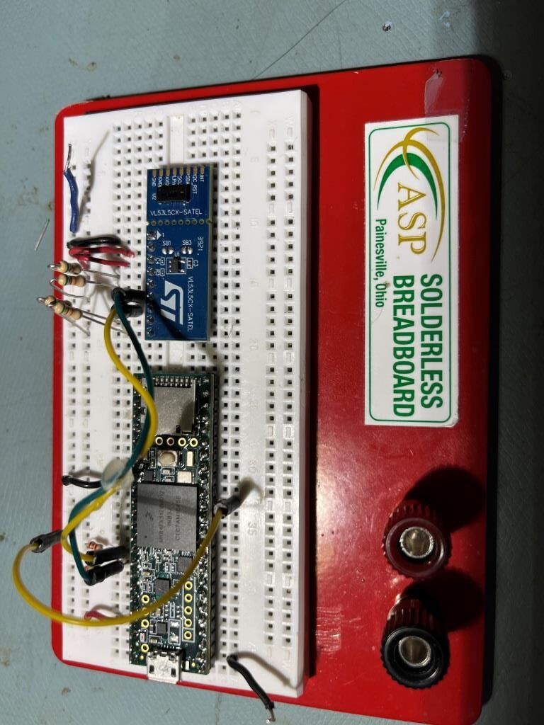
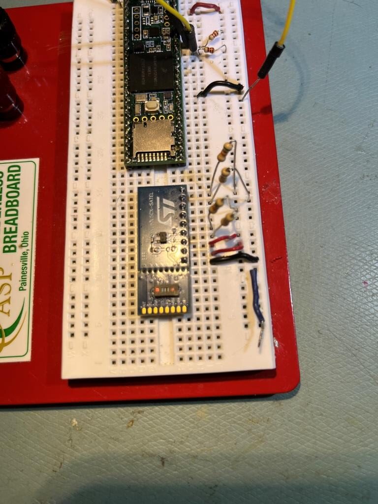
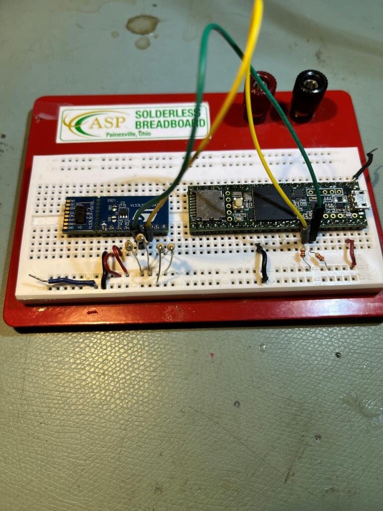
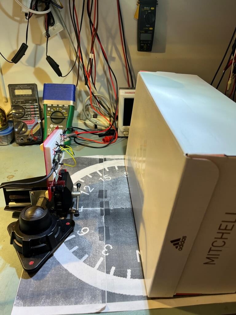
After receiving the modules, I hooked it up to a Teensy 3.5 as shown below. I wasn’t able to find any information about how to wire this unit to an Arduino (ST’s information assumes you have a NUCLEO board), so I had to kind of piece information together from multiple sources. I used Sparkfun’s schematic (I used 51K instead of 47K resistors) and connected PWREN (power enable) to 3.3V via a 51K.

ST Micro eval board for VL53L5CX ToF distance sensor

Then I loaded Sparkfun’s Example1 code, which simply prints out the values from all 64 zones in a timed loop. Here is some representative output:

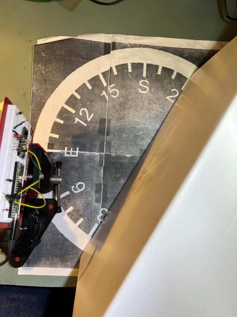
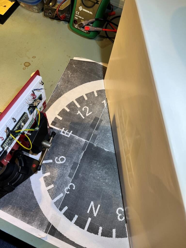
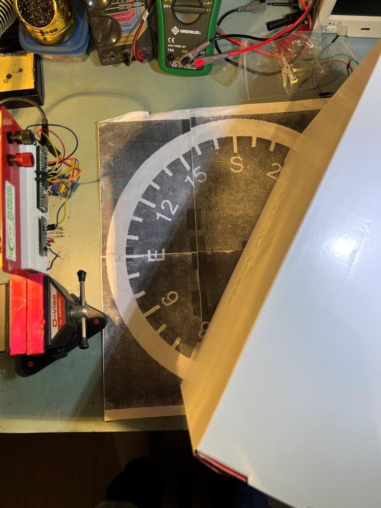
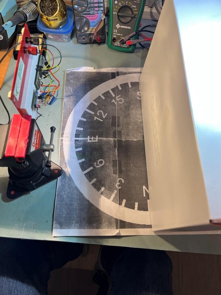
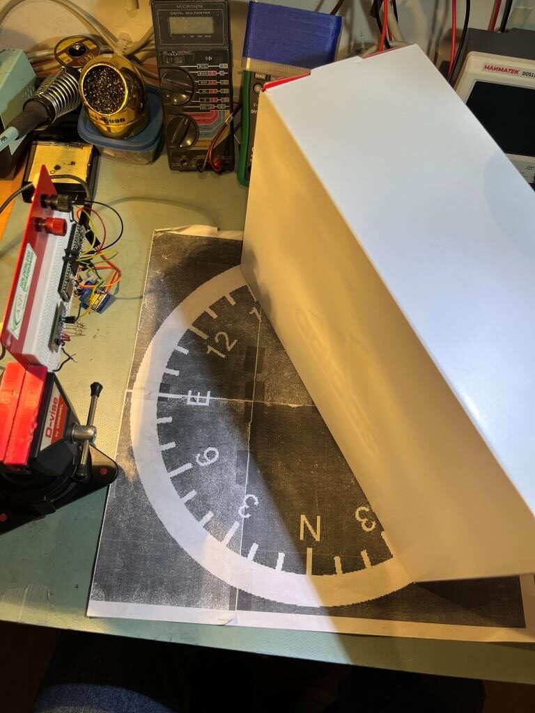
Then I set up an experiment with a nice white planar surface (the shoebox my recent B-ball shoes came in) at a distance of about 16cm, and observed the output for +30º, 0º (parallel), and -30º orientation conditions, as shown in the plots and photos below:

Experimental setup

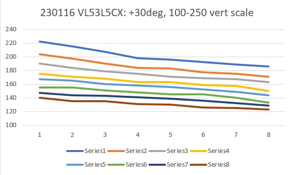
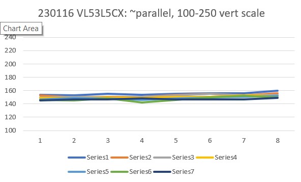
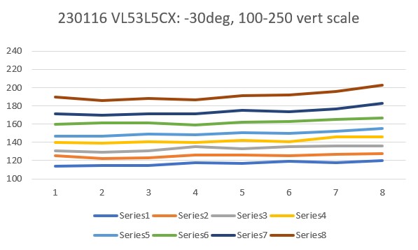
For comparison purposes, all three plots above were plotted on the same scale (100-250). Looking at the blue (Series1) and brown (Series8) lines in each of these plots, it appears that in the +30º orientation, all Series1 points are well above all Series8 plots, and in the -30º orientation the opposite is true – all Series8 points are well above all Series1 points. In the parallel case, all eight series points are crammed together between 140 & 160mm. The physical distance between the sensor and my ‘plane’ (shoebox) was measured at about 165mm, pretty close to the sensor values in the parallel case. So, it looks like it should be pretty easy to discern parallel, +30º, and -30º conditions, and probably reasonable to estimate the +/-10º and +/-20º cases as well.

18 January 2023 Update:

Today it occurred to me that I didn’t really know how the VL53L5CX sensor would respond to ‘wall’ angle changes when oriented in the ‘other’ direction (with the sensor oriented vertical to the floor instead of horizontally as it was above). So, I re-oriented the plugboard in my vise with the sensor mounted vertically, and redid the above experiments, with the results as shown below:

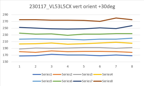
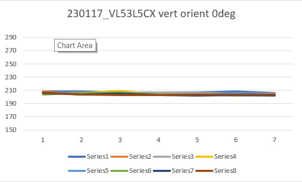
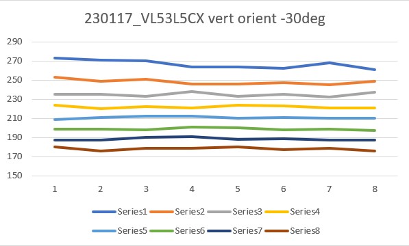
From the above results, it appears that the ‘sensor vertical’ case is more suited to plane orientation measurement than the ‘sensor horizontal’ one. Not sure why this is, but the data is pretty clear.

19 January 2023 Update:

In another email exchange with John Kvam, he wasn’t happy with the fact that the ‘sensor horizontal’ and ‘sensor vertical’ results were different, as the beam transmit/receive geometry is a square pyramid. He thinks some of the beam might be missing the top of the ‘wall’ or hitting the floor, distorting the results (presumably of the ‘horizontal sensor’ results, as the ‘vertical sensor’ results look pretty clean.

So, to address this question, I did another set of runs with the ‘resolution’ parameter set to “4×4” rather than the default “8×8”, and redid the experiments with both ‘horizontal’ and ‘vertical’ sensor orientation, with the following results:

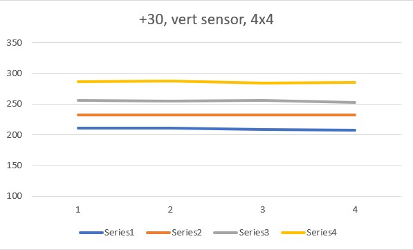
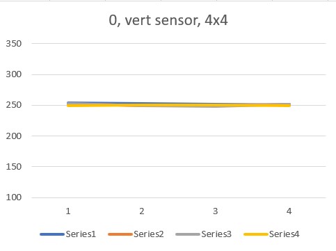
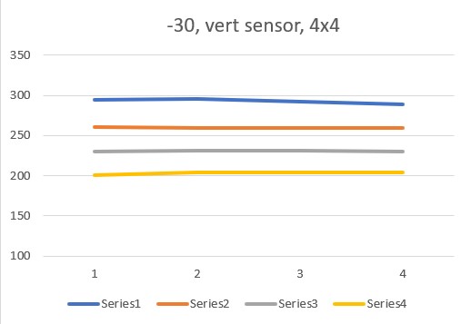
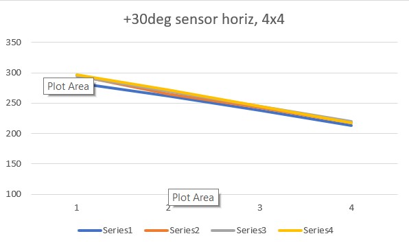
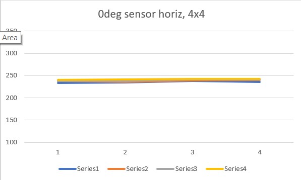
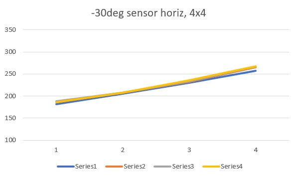
The ‘4×4’ plots above agree quite well with the original set of ‘8×8’ plots, in both shape and magnitude. However, they still show differences between the ‘horizontal’ and ‘vertical’ sensor orientations, which is not what John was expecting.

It occurred to me that the output from my little Sparkfun example is either a 4×4 or 8×8 array of sensor values, so I wasn’t sure what the ‘proper’ way of plotting this data was – I had just accepted Excel’s default which was to plot row by row. As an experiment, I tried switching the rows and columns, whereupon I got the following plots:

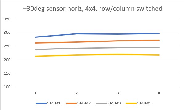
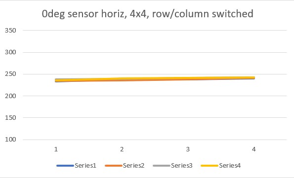
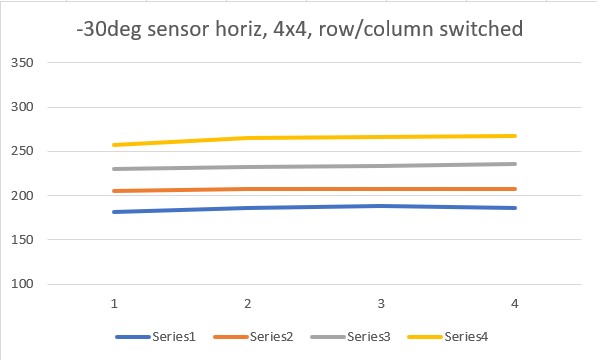
So it appears you can get the same result from both horizontal and vertical orientations, but you have to switch the row/column plotting order to get it. Another way to put it would be that you can select which plot behavior you want by selecting the row/column plotting order – interesting!

To recap this point, here’s a typical 4×4 output:

If this is plotted in normal row by row order, you get this plot:

But the same data, plotted in column by column order produces this plot:

Here’s the actual code that produces the output data:

The line

Reads the entire 4×4 or 8×8 array into memory, and then the doubly-indexed loop prints it out. This is all pretty straightforward, except for how the data is interpreted graphically. As the comments in the code indicate, the printout indexing arrangement is intended to flip the data to undo the physical transformation produced by the physical arrangement of sensor’s transmitter and receiver.

My use case, where all I want is the robot’s orientation angle w/r/t a nearby wall, I don’t really care if the data is transposed horizontally or vertically, as long as it stays the same from measurement to measurement. So, I’m beginning to think that I could simply select the array loading and/or plotting arrangement that gives me the ‘sloped line’ version, and derive the wall orientation from the slope of any of the 4 (or 8) lines

21 January 2023 Update:

After getting the SparkFun VL53L5CXA demo to work, I modified it to compare the first and last values from the first line of the 4×4 measurement array, and used the difference between these values to drive a small RC servo with an attached VL53L5CX module. Then I moved my ‘wall’ around to verify that the setup would, in fact, track the wall plane. Here’s the entire program:

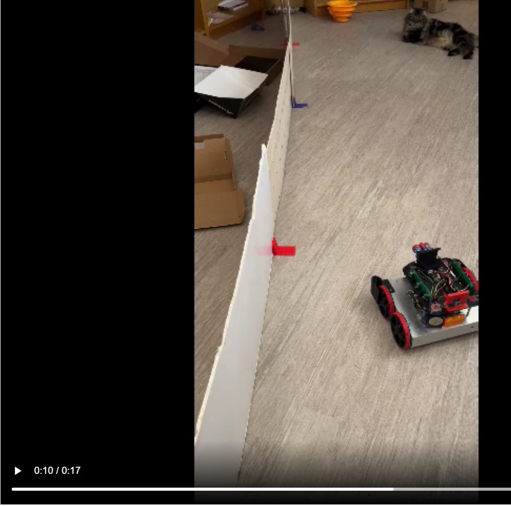
And here is a short video showing the results:

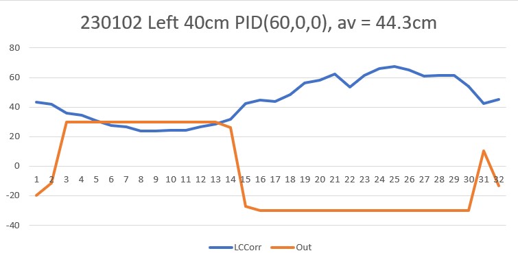
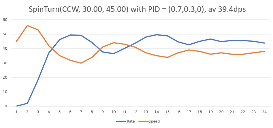
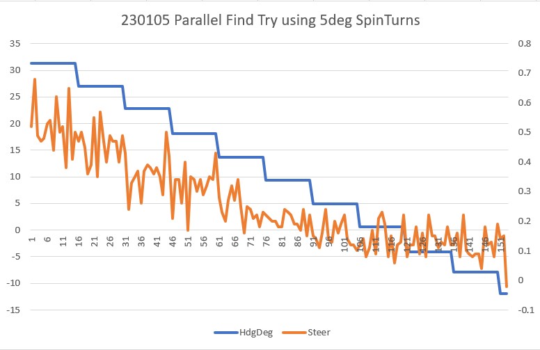
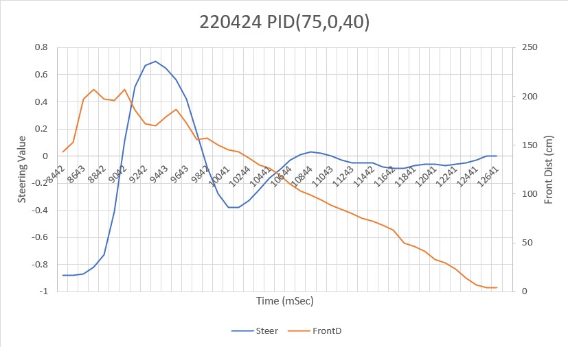
In the above, the servo is moved in 10deg steps to attempt to zero out the difference between the first and last distance measurements from the first row of the 4×4 array. The loop timing (500mSec/loop) is very slow and the algorithm is a simple as it gets, but it appears that this very simple algorithm actually works pretty well.

Next steps are to reduce the loop delay, and reduce the servo step size from 10deg to 1deg, or even use a step size proportional to the error term. Here’s another short video showing the tracking behavior with a 30Hz ranging frequency and a slightly more aggressive servo positioning algorithm.

So it appears clear that the VL53L5CX can be used to track a nearby wall, at least in this servo-enabled configuration. The remaining question is, can I substitute my robot’s wheel motors in the place of the above RC servo and get the same sort of ‘parallel tracking’ behavior as shown above. If not, then I might still be able to use a single sensor per side by mounting it on a servo as in the above configuration. The servo-mounted configuration might even be better, as the sensor would remain broadside to the nearby wall, even if the robot wasn’t. This might facilitate better ‘move to desired left/right distance’ performance because no distance compensation for orientation would be required, and better wall offset tracking for the same reason.

20 March 2023 Update:

As one result of my recent ‘field’ tests with ‘WallE3_Complete_V2’ (see this post), I discovered that the maximum distance capability (approximately 120cm) of my VL53L0X sensors was marginal for some of the tracking cases. In particular, when the robot passes an open doorway on the tracking side, it attempts to switch to the ‘other’ wall, if it can find one. However, If the robot is tracking the near wall at a 40cm offset, and the other wall is more than 120cm further away (160cm total), then the robot may or may not ‘see’ the other wall during an ‘open doorway’ event. I could probably address this issue by setting the tracking offset to 50cm vs 40cm, but even that might still be marginal. This problem is exacerbated by any robot orientation changes while tracking, as even a few degrees of ‘off-perpendicular’ orientation could cause the distance to the other wall to fall outside the sensor range – bummer.

The real solution to the above problem is to get a better side-distance sensor, just as I did by changing from the Pulsed Light LIDAR front distance sensor to the Garmin LIDAR-Lite V4/LED one. For the VL53L0X side sensor, the logical choice is the VL53L5CX sensor; not only does the -5CX sensor have more range (200-400cm), but as I was able to demonstrate above, only one sensor per side is required for orientation sensing. The downside is it will require quite a bit of reconfiguration of the second deck, both in terms of hardware and software – ugh!

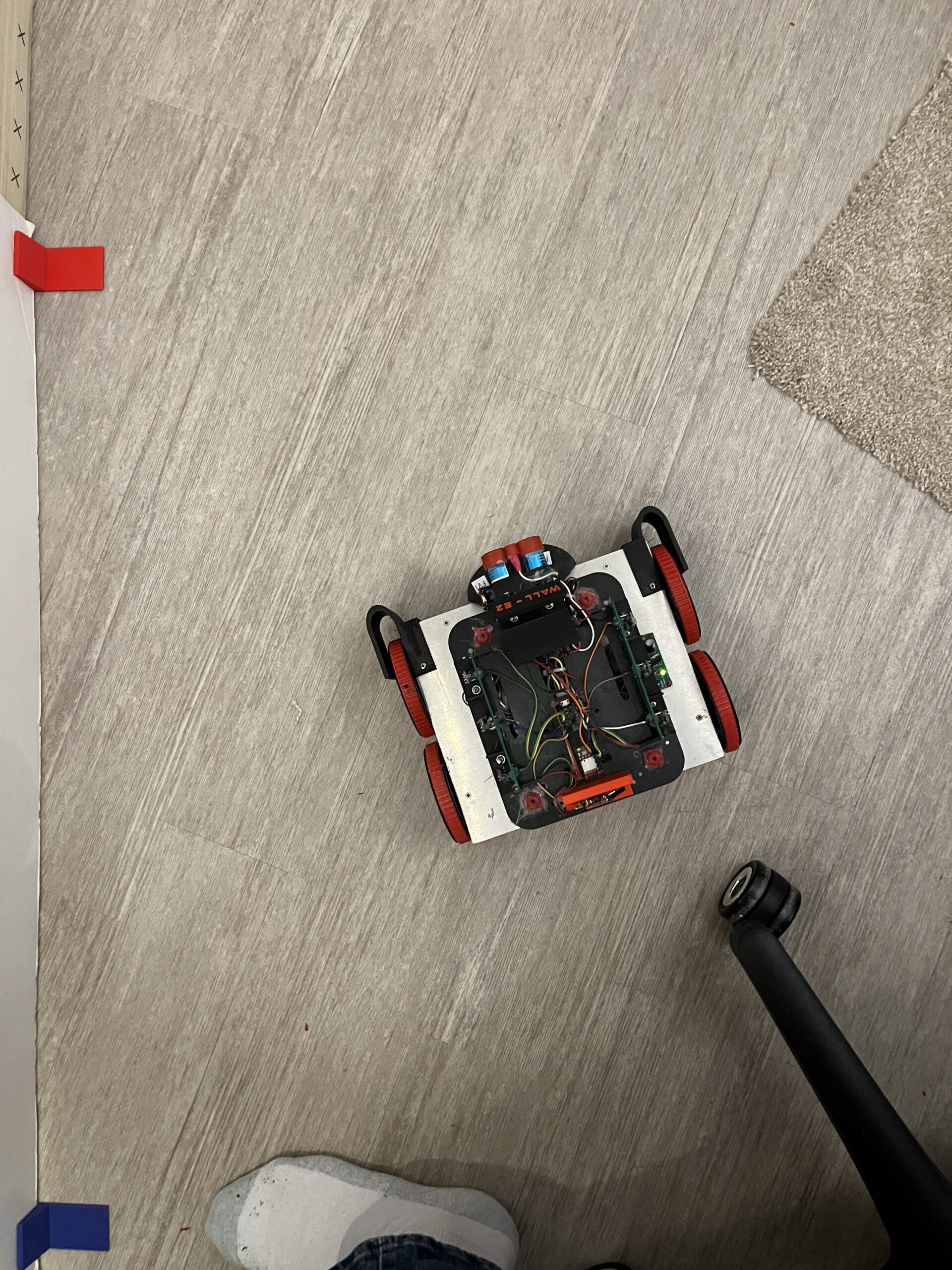
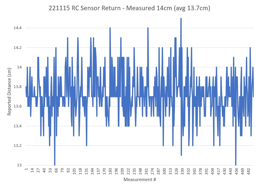
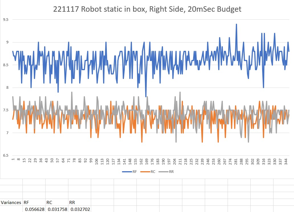
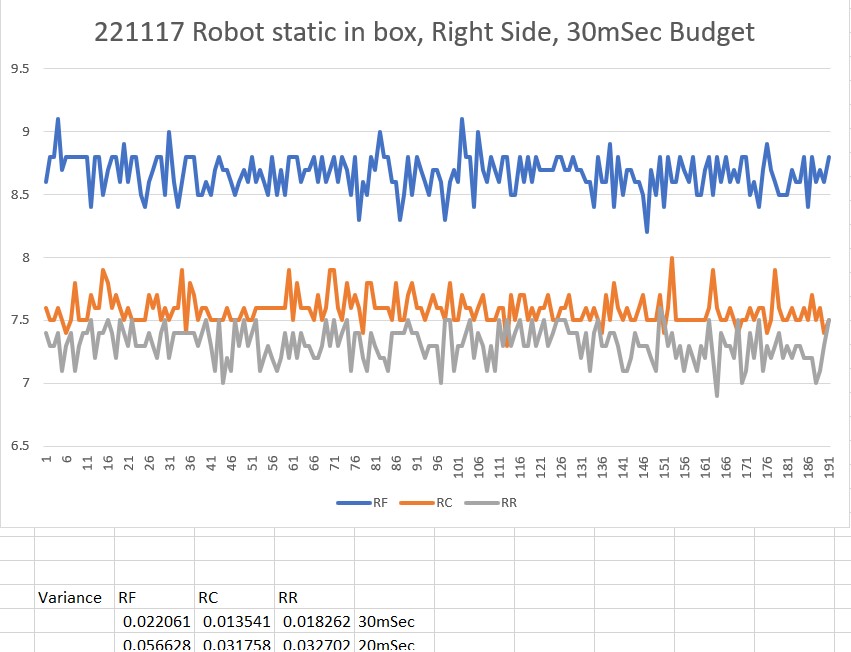
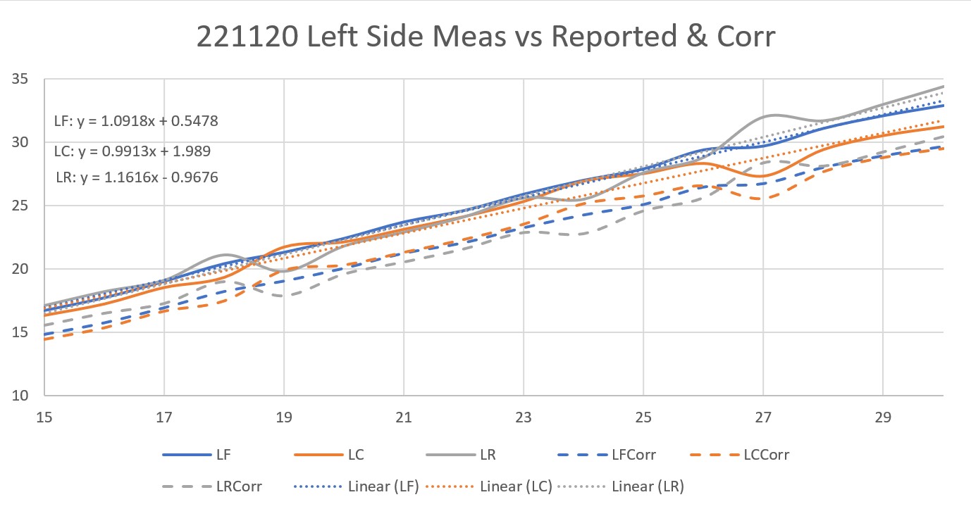
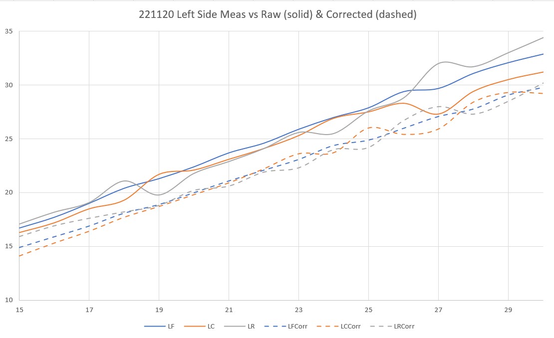
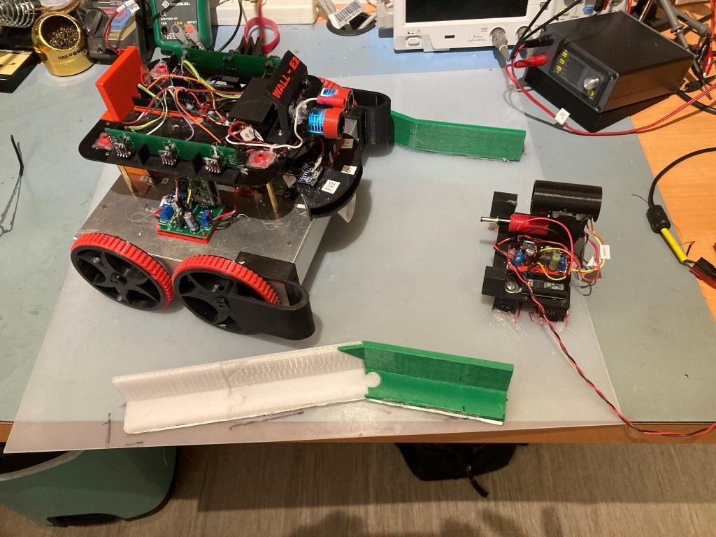
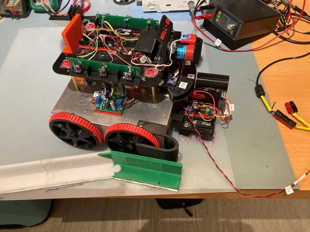
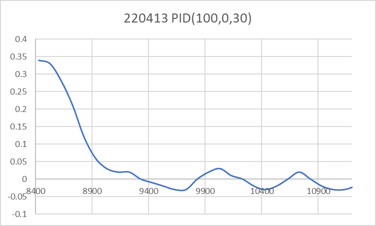
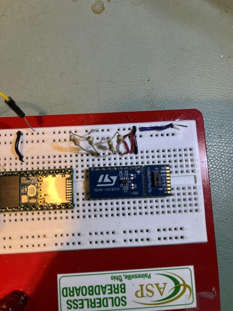
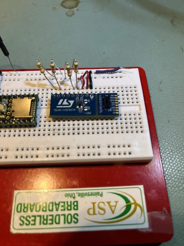
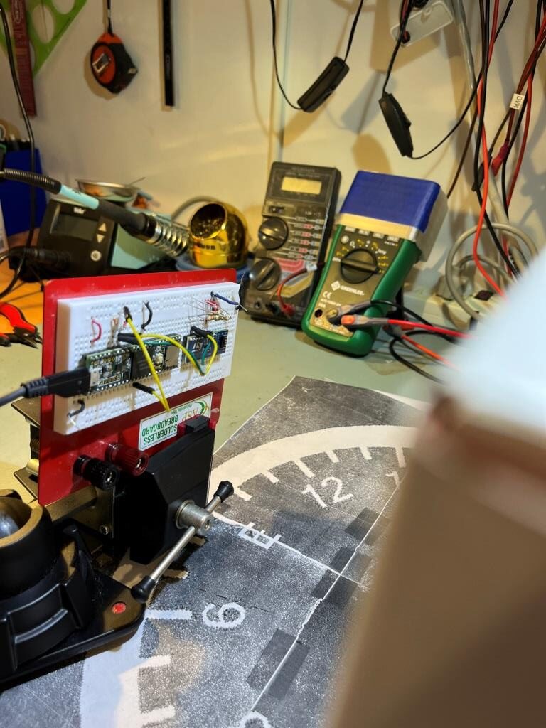
To confirm the distance specs for the VL53L5CX sensor, I reconstructed the above circuit from my and made some tests to measure the maximum distance, as shown below:

VL53L5CX Distance measuring setup

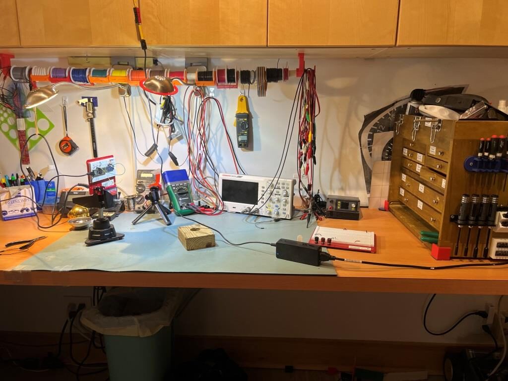
Unfortunately, the tests showed that I wasn’t really going to get any additional range out of the VL53L5CX unit, and in addition range determination would be complicated by the fact that the field-of-view for the VL53L5CX is much broader than for the VL53L0X. This would mean that when mounted on WallE3’s second deck, the sensor would ‘see’ the floor as well as the target wall, giving skewed readings across the array. I think I would still be able to figure that out (i.e. only look at the SPADS on the bottom or top, whichever corresponds to ‘not floor’) but still a PITA. The big problem though, is that I no longer think the -5CX would be enough better to justify the expense (time and money and aggravation) of changing from the -0X. Bummer!

More to follow, stay tuned

Frank

WallE3 Wall Tracking, Revisited

Posted 12/23/22

In the last couple of months I have made some significant improvements in WallE3’s capabilities. I started by completely re-doing the compensation algorithms for the seven ST Micro’s VL53L0X time-of-flight distance sensors (two each 3-element side-looking arrays and one rear-looking distance sensor). I followed this with improvements to both the ‘spin turn’ and ‘rolling turn’ features.

Next, I went back through my ‘MoveToDesiredLeft/Right/Front/RearDistCm()’ family of subroutines and made sure they were all working properly now with the much more accurate distance compensation algorithms. One interesting thing that came out of this effort was the realization that shorter measurement intervals (i.e. 50mSec vs 200mSec) produced an unintended side-effect of making ‘Stuck’ detections much more prevalent. This occurs because the appropriate (front or rear) 50-element distance array fills up much faster at 50mSec/measurement than it does at 200mSec/measurement, so identical (or nearly identical measurements will cause a stuck detection earlier (5 measurements/sec means a 50 element array will fill in 10 sec but 20meas/sec fills the array in 2.5sec. When I used 50mSec/meas in the ‘MoveToDesired…()’ routines, the robot would often exit the routine with a ‘stuck’ error code as it slowed down approaching the desired distance condition. These functions do fine with a more coarse time interval (eliminating the ‘stuck’ declarations), so I went back to 200mSec/measurement.

Now I am going to try to incorporate the above improvements into my previous wall track testing program, ‘WallE3_WallTrackTuning_V4’. As usual, I will start by creating ‘WallE3_WallTrackTuning_V5’ as a clone of ‘_V4’ and start making changes from there.

WallE3_WallTrackTuning_V5:

I am going to try and make WallE3_WallTrackTuning_V5 as ‘clean’ as possible, removing as much ‘dead’ code as possible and consolidating things like sensor measurement intervals.

Timing intervals:

Searching through the code for ‘elapsedMillis’ objects, I see the following global declarations:

Then I did a search for “MSEC” all upper case and found:

The front LIDAR sensor starts to generate errors for long distance measurements when the measurement interval falls below 200mSec

The VL53L0X time-of-flight sensors need a ‘measurement time’ of 50mSec or greater. This is handled by the VL53L0X array Teensy, but it means that UpdateAllEnvironmentParameters() shouldn’t be called more frequently than 20HZ.

The MPU6050 can support an update interval of 30mSec or greater, and this time is used for all turning operations.

Telemetry readouts should occur no more than once every 200mSec.

MoveToDesiredFront/Back/Left/RightDistCm()

Based on my recent work on these functions, it looks like PID = (1.5, 0.1, 0.2) will work for all cases, so all I have to do is modify the existing ‘OffsetDistKp/Ki/Kd’ values. Note that in my testing these were parameters to the function call instead of program constants, but now I can go back to just having the desired offset as the only parameter.

So, I copied each of the above functions to WallE3_WallTrackTuning_V5 from WallE3_FrontBackMotionTuning_V1, removed Kp,Ki,Kd from the sig, and replaced all occurrences with OffsetDistKp/Ki/Kd. I also ported the CorrDistForOrient() function, as it is required by the MoveToDesiredLeft/Right() versions

01 January 2023 Update:

After getting the ‘MoveTo…’ functions working, I discovered that ‘RotateToParallelOrientation()’ didn’t work well at all, and in fact found a note from my former self that the function was ‘fatally flawed’ – oops! So, I revisited my ‘WallE3_ParallelFind_V1’ part-task project to see if I could get it to work better now that VL53L0X distances are being reported as float vs integer objects, and after what I hope is much better sensor error compensation. As shown in this post, RotateToParallelOrientation() now works much better, albeit somewhat slowly, with PID = (20,4,0).

Offset Capture with ‘RotateToParallelOrientation’ ‘at end

02 January 2023 Update:

Starting to make some full-up left wall tracking runs, using the updated code from earlier work. In particular, I am trying to see if my older idea about combining an offset-driven steering angle modifier for the PID tracking algorithm will work. The ‘offset_factor’ incorporates the distance error into the reported steering angle, which in turn is used in the PID machine to drive the combined steering angle to 0.

Here’s an early run:

This worked, ‘sorta’. Part of the problem with this run is the robot’s orientation with respect to the wall at the start of the run. This is supposed to be parallel with the wall, but it obviously isn’t, and I don’t know why. Here’s the data from the ‘RotateToParallelOrientation()’ step

This certainly looks good – with a front/rear distance difference of only 0.3cm, and a steering value of 0.02. However, as shown in the following screengrab of the above video, the robot’s orientation just after the parallel find operation is anything but parallel

movie frame grab just after ‘RotateToParallelOrientation()’

I re-instrumented the ‘RotateToParallelOrientation’ function to print out 10 sets of front/back distances directly after completing it’s ‘ParallelFind’ operation, and made another run. The photo below shows the ending orientation, followed by the data

Robot orientation immediately after ‘RotateToParallelOrientation()’

According to the photo, the robot is definitely not oriented parallel to the wall. However, according to the telemetry data, it is (44.4 front, 44.2 rear, steerval = 0.02). Even curioser, the actual physical measurements taken using a tape measure show that the front/rear distances are about 47/44cm, or a steerval of about 0.3! Something is definitely wrong here.

Uncommented the #DISTANCES_ONLY define and re-ran, with the robot position/orientation unchanged:

In the above data, the front distance varies from 42.6 to 44.6cm with an average of 43.7cm, and the rear distance varies from 44.1 to 45.5cm with an average of 44.8cm.

So the program thinks the front/back distances are closer together than the tape measure does (44.5/45.0 vs 47/44). This is a pretty big discrepancy. Rotating the robot to be physically parallel with front/rear distances = 40cm, I get:

When the robot is physically parallel, the reported front distance varies from 38.2 to 39.2cm with an average of 38.8cm, and the rear distance varies from 36.7 to 38.3cm with an average of 37.9. The left steering value varies from 0.02 (38.8/38.1) to 0.14 (38.9/37.5) with an average of 0.09.

Well, it looks like the average reported distances and steering values are pretty close to reality, so maybe my original calibration efforts aren’t entirely screwed up. However, it is abundantly clear at this point that my current ‘RotateToParallelOrientation()’ algorithm isn’t reliable, due to very noisy distance value measurements.

01/09/23 Update:

After getting ‘RotateToParallelOrientation()’ working better (now it just uses the array front/rear distance measurements to calculate the off-parallel angle, and then does a ‘SpinTurn’ by that amount), I resumed the effort (see the 02 January Update above) trying to determine if my older algorithm for combining the raw steering value with an ‘offset adjustment factor’ based on the robot’s distance from the desired offset distance would now work better given the improvements I have made in VL53L0X sensor error compensation and off-parallel distance measurement compensation.

As it turns out, the answer seems to be ‘no’. After a multitude of runs with my test wall set up for two 30-45deg ‘breaks’, I couldn’t find any set of PID values that would allow the robot to track the wall – it always either took off for parts unknown, or crashed into the wall at some point.

So, back to the original algorithm of using the wall offset distance directly in the PID engine.

11 January 2023 Update:

I’m confused – not an unusual state for me to be in – but still…..

After all the above improvements, I still was unable to produce reasonable tracking performance using either the steering value or the offset distance as the parameter to be controlled. And, even more confusing, I have an entire post dedicated to demonstrating successful wall tracking using the orientation-angle-corrected distance to the wall as the input to the PID engine, with the desired wall offset as the setpoint, as shown here:

With this algorithm, I settled on PID(3,0,1) as the best parameter set, with the result shown in this short video (copied from the above post):

Wall tracking using corrected distance measure as input, and desired offset as the set-point

And then, I have another post demonstrating that using the steering value as input and 0 as the setpoint also works, as shown in this short video with PID(300,0,300)

Right-side wall tracking using steering value as input with PID = (300,0,300)

Here’s the data and short video from a run on my longer ‘4 meter’ test range with two 30º breaks:

Using steerval only. Note monotonically decreasing distance

Even more confusing, it appears that the earlier (September 2021) trial using the steering value input also used the measured center distance to modulate the steering value so the robot would tend to track the steering value but also trend toward the desired wall offset distance. Here’s the tracking code from FourWD_WallTrackTest_V3:

In the above code snippet, ‘Lidar_RightCenter’ is in mm, so WALL_OFFSET_TGTDIST_CM must be multiplied by 10 to match units.

At this point I am thoroughly confused, (but hopeful, since I have evidence from an earlier version of myself that something (actually two somethings) actually work. I believe the next step is to see if I can use my WallE3_WallTrackTuning_V5 code to consolidate everything down to something that works.

12 January 2023 Update:

I went back and loaded up WallE3_WallTrack_V2.ino and ran it on my 4m ‘range’ with two 30º breaks. The robot tracked amazingly well, as shown in the following telemetry output and Excel plot

WallE3_WallTrack_V2’s tracking algorithm uses the difference between the desired and measured offset distances to ‘tweak’ the steering value, as discussed above, so clearly this works – or at least doesn’t screw things up too badly. In the above telemetry output, the ‘Steer’ column is the steering value after the offset distance adjustment shown here

So at the point where the robot hit the minimum center distance of about 154mm, the steering value adjustment would be (154-400)/1000 = -0.246. The total steering value term at this point was 0.23, which means the ‘raw’ steering value was +0.016 and the offset distance error term accounted for ~97% of the total. This is good evidence that including the the distance offset term works.

My new new new plan is to focus on my October 2022 post that uses the orientation angle corrected offset distance as the input to the PID engine, and see if I can incorporate this, along with all my recent updates/bugfixes into WallE3_WallTrackTuning_V5

WallE3 Spin Turn, Revisited

Posted 23 December, 2022

Just over a year ago I made a radical change to WallE2’s form factor to improve it’s turning performance. Since then I have been making other changes and improvements to WallE3, including a recent successful effort to improve WallE3’s ‘rolling turn’ capabilities. Based on that, this post describes a similar effort to improve WallE3’s ‘spin turn performance.

To date, WallE3’s ‘spin turn’ performance has been lackluster at best. Rather than turning smoothly, it tends to ‘motorboat’ it’s way through the turn, starting and stopping several times through the turn. After achieving some success with smoothing out the ‘rolling turn’ feature, I decided to take another crack at ‘spin turn’.

I started by creating yet another part-task program that does nothing but support spin turn operations. This program accepts a set of parameters, calls the existing ‘SpinTurn()’ subroutine to execute the specified spin turn, and then returns to the parameter entry state for another go.

The starting point for the effort was a 90º CCW turn at 45º/s, with PID = (1,0,0). As shown below, this produced a nice smooth turn, but way too slow (17º/s vs 45º/s):

After a coupe of dozen trials, I gradually worked my way up to a ‘final’ PID of (0.7,0.3,0). Here are plots and videos for various turn lengths and rates.

SpinTurn(CCW,30,45)PID(0.7,0.3,0)

SpinTurn(CCW,60,45)PID(0.7,0.3,0)

SpinTurn(CCW,90,45)PID(0.7,0.3,0)

After running these tests, I decided to see how WallE3 would perform on carpet with these same settings. As shown below, carpet performance was pretty much identical to the smooth surface runs.

SpinTurn(CCW,30,45)PID(0.7,0.3,0)
SpinTurn(CCW,60,45)PID(0.7,0.3,0)
SpinTurn(CCW,90,45)PID(0.7,0.3,0)

So, with much better performance now for both the ‘rolling turn’ and ‘spin turn’ features, it is now probably time to revisit the whole wall-tracking thing, and see if I can achieve better performance than in past efforts.

Stay tuned,

Frank

Using mklink to centralize Teensy OTA Files

Posted 20 December 2022

This post describes the actions I have taken to centralize the ‘board.txt’ and ‘TeensyOTA1.ttl’ (Tera Term macro) locations that facilitate the Teensy OTA capability, so that all my various firmware projects targeted at my wall-following robot all use the same set of files. This is done by using the Windows ‘mklink’ command to create ‘hard’ links from the various program folders to a single folder called ‘Robot Common Files’.

For the past five or six years I’ve been working on a 4-wheel robot project to autonomously navigate around my house using a (by now) fairly sophisticated wall-following algorithm. As I have worked through the various problems, I’ve gone through at least three different physical form factors, starting with a 3-wheel (two driven wheels, one castering wheel) and ending up (so far) with a custom 4-wheel ‘wide-track’ model.

Also along the way I have gone through any number of software versions. I work mainly with the Arduino ecosystem, but I don’t use Arduino directly. I use Microsoft Visual Studio 2022 Community Edition with the Visual Micro extension, and this is a great platform.

My latest hardware upgrade was to replace my original Arduino Mega 2560 processor with a Teensy 3.5 main processor, with a firmware update to achieve over-the-air (OTA) updates using a Wixel RF pair.

I now have at least twenty different software/firmware projects that I run on the robot for different reasons. I have a ‘main line’ project that incorporates all features required to full execute autonomous wall-following, and then I have lots of smaller projects aimed at exercising some small subset of the full feature set – things like distance calibration testing for the robot’s two 3-element VL53L0X time-of-flight distance sensors, and for testing out different ways of managing ‘rolling’ and ‘spin’ turns, and different algorithms for wall-tracking. All of these projects use the same ‘over-the-air’ (OTA) firmware/hardware configuration for firmware updates. Up until now I have been simply copying the two required files – ‘board.txt’ and ‘TeensyOTA1.ttl’ (a Tera Term macro) from project folder to project folder, but a recent Visual Micro update broke my OTA routine, and I discovered that having these two files copied into multiple project folders didn’t work so well – oops!

So, I decided to create ‘Robot Common Files’ folder in my Documents\Arduino folder tree, place these two files (along with the required FlashTxx.cpp/h files and my ‘enums.h’ file) into this folder, and then use the ‘mklink /H’ command (12/23/22 note: Admin privileges are not required) to create ‘hard’ links from each project’s folder to the single files in m Robot Common Files folder. The commands I used to accomplish this were:

where ‘WallE3_AnomalyRecovery_V2’ gets replaced each time with the actual project name

Now, when I want to edit either the ‘board.txt’ or ‘TeensyOTA1.ttl’ file, I can simply right-click on the filename in any project folder and select ‘edit with NotePad++’, and the single file in Robot Common Files gets opened for edit, and the changes are immediately available in all projects that use the Teensy OTA feature.

31 January 2023 Update:

After trying this trick a few times, I realized I had left out a step, so this update fixes that. Below is the entire Cmd line session for my latest ‘new project’:

The first line above shows the ‘cd’ step, which I had left out of the previous post. After that, I just copy/pasted the ‘mklink….’ text for each of the two files, and then everything was wonderful again.

Stay Tuned,

Frank

Wall Parallel Find PID Tuning, Part II

Posted 01 December 2022

I thought I had the ‘parallel find’ problem solved about 18 months ago, back in April of 2021, but it seems this is a problem that refuses to die (well, up until now, anyway). This post describes the ‘new, new!’ solution, based on much improved distance measurement performance from the VL53L0X time-of-flight sensors and associated software. Basically, I discovered that I had been doing VL53L0X distance calibration all wrong, and a big part of the problem was my use of an integer instead of floating point data type to represent distance values. The VL53L0X sensor reports distances in integer millimeters, but when I converted the integer mm values to integer cm (without even rounding – but by truncation – yikes!) the resulting loss of precision caused significant problems with the parallel find algorithm.

So, after converting all my VL53L0X distance variables from integer to float (which turned out to be pretty easy as I had practiced good modularity and low coupling – yay!), I started over again with a two stage strategy. The first part addressed the calibration problem by redoing a series of tests to acquire compensation curves for both the right and left-side sensor arrays which were then programmed into the Teensy 3.5 processor that handles the VL53L0X arrays. The second part was to revisit the ‘parallel find’ algorithm. This post describes the result of the second part – revisiting the ‘parallel find’ algorithm.

The parallel find algorithm implements a two-stage search for the parallel condition, defined as the robot (or, more accurately, the relevant VL53L0X array) orientation that produces identical distance readings from the front and rear sensors of the relevant (i.e. left or right) array. The first ‘coarse’ stage searches for the change in sign of the steering value, and the second ‘fine tune’ stage searches for a steering value < 0.01, meaning that the front and rear distance values are nearly identical.

Here is the code for the parallel find subroutine:

And here is a short video and the telemetry output for a successful parallel find run

So it appears that my original parallel find algorithm now performs much better, due mainly to the more accurate distance reporting obtained by changing from integer to float data type, and better distance compensation curves for each of the six sensors in the two VL53L0X arrays. Now I need to back-port this improved code into my main robot navigation code, probably by way of the Wall Track part-task program described in my earlier ‘More Wall Track PID Tuning‘ post.

29 December 2022 Update:

After going through some additional ‘part-task’ tune-up exercises, I started the process of integrating all the changes back into my Wall Tracking PID Tuning code. After the usual number of screw-ups I got the left-side offset capture feature working up to the point of turning back parallel to the wall. The code at this point just used ‘SpinTurn()’ to turn 30º in the opposite direction as the first turn away from the wall, with a note that this was done because ‘Parallel Find is fatally flawed’. Well, since I had just gotten through testing this feature I thought I could just drop it in. When I did, the robot promptly turned in the wrong direction and started spinning – yikes! Back to the ‘Parallel Find’ drawing board!

After making some code changes to make the part-task code a bit easier to use, I got everything working again, with basically the same PID values (100,0,0) as before. Here’s the output and a short video from a run:

30 December 2022 Update:

Not so fast, pardner! Well, it seems I was a bit premature about completing this effort – After a few more trials I realized this wasn’t working anywhere near as well as I thought – oops!

So, after lots more trials aimlessly wandering around PID space, I came up with new values that *seem* to work (for the left side case, at least). I also discovered that I really don’t need a two-stage process (‘coarse’ tune followed by ‘fine’ tune) to get a decent result, as long as the robot turns slowly enough to allow the distance measurement changes to keep up. Here’s are a couple of runs (telemetry output and short video) for the new setup.

05 January 2023 Update:

Well, even the above ‘slow as she goes’ idea doesn’t work all the time or that well. I wound up trying to instrument what is going on by doing the following

  • Turning the robot in 10⁰ steps, followed by a 1500 mSec pause to let the measurements catch up
  • At 100mSec intervals during the 1500mSec pause, computing and displaying the 5-pt running average of the left front and rear distances, along with the running average computation of the steering value.

When I did this, I got the following plot

1500mSec plot of the steering value computed from a 5-pt running average of the left front and left rear distances. Each line is a different 10deg angle orientation, with the lowest (yellow) line representing a parallel or near-parallel orientation

As can be seen from the above plots, there is significant variation over the 1500mSec interval, even though the robot is stationary. In particular, the last plot shows that at the start of the 1500mSec stationary period, the steering value goes from 0.15 (i.e. not parallel at all) to near zero (i.e. very parallel), even though the robot isn’t moving at all.

I have no idea why this is happening, but it sure screws up any thoughts of rapidly finding a parallel orientation, and even sheds significant doubt on the entire idea of using multiple VL53L0X sensors for wall tracking – UGH!!

This time I tried a ‘parallel find’ run using 5⁰ SpinTurn() steps, with no averaging. Here’s the data, and a short video showing the result

This actually looks pretty good, and the unaveraged distance sensor results, although noisy, behaved reasonably well.

07 January 2023 Update:

As I was drifting off to sleep After yesterday’s ‘successful’ trial runs, I was happy visualizing the robot using the ‘SpinTurn() facility to gradually turn to the (mostly) parallel position (I’m a visual person, so I often turn programming problems into visual ones), it suddenly struck me that I was taking the long way around the barn; here I was sneaking up on the parallel orientation by small SpinTurn increments waiting for the steering value to change signs, when actually all I had to do was use my ‘GetWallOrientDeg(float steerval)’. This function takes the current steering value as the sole parameter and returns the current orientation angle with respect to the nearest wall; with this information I could use SpinTurn() to rotate to the parallel orientation in one shot – cool!

So, I recoded my test program to do just that, with the ‘enhancement’ (I hope) of taking a second or so at the start to acquire a 10-point average of the steering value, so as to, hopefully, reduce errors due to noisy distance sensor outputs. Here’s the output and a short video showing the result:

This seemed to work very well, and is a much simpler algorithm than trying to use an ‘on the fly’ steering value and a PID machine. I believe with this result I can get back to the problem I was originally trying to solve – that of reasonable wall following.

02 February 2023 Update:

Referring to my current quest to incorporate the results from all my previous ‘part-task’ programs into a ‘WallE3_Complete_V1’, I have been going through each ‘part-task’ program to verify results, and then incorporating the results (usually in the form of a single function) into the ‘complete’ program. When I got to WallE3_ParallelFind_V1, I discovered that, although I had made quite a bit of progress, including drastically simplifying the ‘parallel find’ algorithm, it still didn’t work very well.

After some additional work, I now think that ‘parallel find’ is ready for inclusion in the complete program. Here’s the functional code from WallE3_ParallelFind_V1:

The above code will replace the code in ‘RotateToParallelOrientation()’. See my post on consolidating everything into a ‘Complete’ program for more details

Stay tuned,

Frank

Improving VL53L0X Measurement Accuracy/Precision

Posted 15 November 2022

Last April I described how I determined that individual VL53L0X ‘time-of-flight’ distances sensors exhibited measurement errors, and also described my method for minimizing those errors. This has worked well up to now, but I recently realized that there was another error term I hadn’t accounted for; the error associated with using integer variables to hold VL53L0X distance measurements.

The left & right 3-element VL53L0X arrays (plus a single rear distance sensor) are managed by a dedicated Teensy 3.5 processor, which retrieves distance measurements from all seven sensors and then calibrates them using the method described in my April post. When requested by the main processor, these measurements (in integer MM) are provided via a I2C link. After receipt from the VL53L0X processor, distance measurements are converted from MM to CM by dividing by 10, ignoring integer truncation.

However, I have recently discovered that this integer truncation may well be more significant that I originally thought, and may be leading to performance issues, particularly with my ‘RotateToParallelOrientation()’ function and wall offset tracking in general. The linear distance between the front and rear VL53L0X sensor on each side is about 8.5Cm. Assuming that all constant errors are calibrated out, the robot will be parallel to the wall when the front and rear sensors return the same value. However, because the distance values only change in 1Cm increments, the actual distances measured by the front and rear sensors can be as much as 1Cm different. 1Cm difference over a length of 8.5Cm is about 7∘ – small, but not necessarily insignificant.

It turned out to be relatively painless to change all VL53L0X distance variables from ‘uint16_t’ to ‘float’, and get everything going again. After making this change I tried some more ‘rotate to parallel’ experiments but the change didn’t seem to make much of an improvement. Poking around a bit more I found out why – the raw measurement data coming from the VL53L0X sensors exhibited a lot of ‘noise’, even with the robot stationary and only a few cm from the nearby ‘wall’. The following Excel plot shows one sensor’s data with the robot approximately 14cm from the wall.

Robot stationary 14 cm from wall

As can be seen from the above the reported distance varies from 13 to about 14.5cm. Assuming that all three right-hand sensors behave similarly, it would be possible for the front sensor to report 13cm while the rear sensor was reporting 14.5cm. Moreover, my parallel find algorithm defines ‘parallel’ as RF-RR ~= 0, so it can (and does) terminate well before or after the actual physical parallel orientation occurs.

Looking through (again) the VL53L0X documentation, I came across the ‘measurement budget’ parameter, which is set by default to ‘30000’ (30msec). In my application I had it set to ‘20000’ (20msec) because I thought at the time that with 7 total VL53L0X sensors, I couldn’t afford 30msec delay for each and still hold to a 200msec system loop period. I later changed the system design to use a separate Teensy 3.5 to continuously poll the sensors and report the latest measurement to the main processor when asked, which essentially eliminated the sensor delay from the overall loop (not entirely, as longer sensor measurement times may mean that physical dynamics aren’t followed quite as faithfully, but fortunately my robot doesn’t do anything quickly).

To test the effect of longer measurement budgets, I placed my robot in a cardboard box with its right-side sensor array about 7cm from the wall of the box, and then took measurements with measurement budgets of20, 30, 40, 50, and 60msec. For each value I plotted the distance output and also calculated the variance for each sensor, as shown in the plots below:

20msec budget – the current configuration
30mse budge with 20 & 30msec variances shown
Showing the effect of 40, 50 & 60 msec budgets

As can be seen from the chart immediately above, a measurement budget of 50msec is noticeably better than that for 40msec (which is itself better than the 20 or 30msec budgets), but the 60msec budget plot shows little improvement over 50msec. Looking The ‘RF’ variance starts at 0.0566 for 20msec, drops to less than half that at 30msec, drops by half again at 40msec, and drops by another 50% or so at 50msec. From there to 60msec is only a change from 0.011074 to 0.01046 (this all assumes that I can draw conclusions like this when not only going up with measurement budget, but going across sensors as well). In any case, I settled on a new measurement budge value of 50msec, as shown below.

New value of 50msec for measurement budget

Note that while the motionless measurement variation has been significantly improved, I still have a problem with different nominal measurements from each sensor; the right-front (RF) sensor insists the wall is about 9.2cm away, while the center (RC) and rear (RR) ones think the wall is about 8 and 7.7cm away, respectively (as a side note, before I changed reported measurement variables from ‘uint_16’ to ‘float’, these values would have been reported as 9,8, and 7cm respectively). I thought I had fixed this problem earlier with a set of correction functions as described here, but I obviously have some more work to do (see this post for more on distance correction)

Stay tuned,

Frank

VL53L0X Distance Measurement Compensation

Posted 20 November 2022

To study the issue of VL53L0X sensor calibration, I set up an experiment where ten measurements from each of the three right-side sensors were collected at distances from 15 – 30cm, as shown below. As can be seen, the ‘raw’ values (no correction) are pretty linear. I used Excel’s ‘trendline’ tool to display the ‘best fit’ linear expression for each line, then used these expressions to calculate a correction expression, (dashed lines)

The actual correction expressions were (cm units):

  • RF: RFCorr = (RF-0.4297)/1.0808
  • RC: RCCorr = (RC-5.0603)/1.0438
  • RR: RRCorr = =(RR-5.6746)/1.0353

Next, I edited my ‘lidar_XX_Correction()’ subroutines in my Teensy_7VL53L0X_I2C_Slave_V4 project to implement the above expressions, and made another run of distances from 15 to 30cm, as shown below.

Before (solid lines) and After (dashed lines) Correction

The above plot shows that the correction algorithm is effective and repeatable, at least on the right side sensors. Now I have to perform the same corrections on the left side and I’ll be all set – at least for this particular part of the ongoing Sisyphean task of educating WallE3, my somewhat retarded autonomous wall-following robot.

Applying the same methodology to the left side sensors, I first captured left-side reported distances for measured values from 15 to 30 cm, same as for the left side. Then, using Excel’s ‘trendline’ calculation feature to derive a correction expression, I added simulated correction lines to the plot, as shown below:

The actual correction expressions were (cm units):

  • LF: LFCorr = (LF – 0.5478)/1.0918
  • LC: LCCorr = (LC – 1.989)/0.9913)
  • LR: LRCorr = (LR + 0.9676)/1.1616

Not much correction is needed for the left-side sensors. However, since I already have the corrections, I might as well put them in; I modified the VL53L0X sensor manager firmware to include the above corrections, and then re-did the calibration plot -this time plotting the pre-correction reported data along with the post-correction reported data, as shown below:

As can be seen from the above plot, left-side correction is pretty good over the entire 15-30cm range – nice!

Stay tuned,

Frank

Wall-E3 Charging Station Integration, Part II

Posted 28 May 2022

After getting the IR homing capability working with Wall-E3, I started working on the ability to recognize the charging beacon during normal wall-following operations, and then transitioning (or not, depending on battery level) to the charge station docking procedure.

The ‘transition-to-charge’ feature assumes that the robot is tracking the right-hand wall within a few meters of the charging station, and detects the beacon. To connect to the charger, the robot must first navigate away from the wall to a point on the IR beacon centerline, turn to line up with the beam, and then follow it to the charger.

As I was testing this feature, I noticed at one point the robot detected the IR beacon while tracking the wall opposite the charger, not the wall where the charger was installed. This is a real problem, because my current ‘transition-to-charger’ algorithm assumes the geometry associated with the common wall case. In the common wall case, the robot makes a 90 deg turn away from the wall and moves to a spot calculated to put it on the beam centerline, but this won’t work at all if the robot is starting from a point on the opposite wall. In that case, the robot needs to travel forward or backward parallel to the opposite wall by a distance calculated to put it on centerline. So, the first thing the robot needs to be able to do is to detect which case (common wall or opposite wall) it is dealing with.

The primary difference between the two cases is how much the robot has to turn away/toward the wall it is currently tracking in order to point directly at the beacon generator; if it is on the common wall, then it may not need to turn at all, or may even have to turn a bit toward the wall to point directly at the generator. If it is currently tracking the opposite wall however, it will have to turn 30-60 deg away from the wall. So, the determination as to which case is in play, the robot needs to measure the number of degrees of heading change required to face the charger; if the heading change is 30-60 degrees, then it is the opposite wall case. If it is just a few degrees, then it is the common wall case.

The following short video shows the two cases and the heading change required to point to the charger in each case.

Turn to beacon performance, for opposite and common wall cases

21 June 2022 Update:

Progress has been a bit slow over the last month, as I’ve been doing other things, including recovering from an eye/scalp injury sustained at the Senior Games in Florida (those old guys can still pack a wallop!). However, I now think I have the charging station homing operation working, at least for the right-wall-tracking (the most common and probably only) case.

As it turns out, I didn’t really need to worry about the problem of the robot picking up the IR homing beacon while tracking the far wall (i.e. the wall perpendicular to the one associated with the charging station). As I noted above, the robot can sometimes ‘see’ a beacon signal above the threshold, but when it does, the steering signal (goes from -1 to +1) is always off scale on one side or another. So, by adding the requirement that the steering signal be within the range of -0.8 to +0.8, this case is entirely eliminated, leaving only the ‘same-wall’ homing case – yay!

I made a number of improvements to the IR homing code, in particular the ‘initial approach’ code that places the robot optimally with respect to the IR beacon beam, so that the subsequent ‘home-to-charging-station’ procedure is almost always successful.

In the following short video, the robot tracks the opposite wall, makes the turn to track the adjacent wall, and then detects the IR homing beacon at the conclusion of the offset capture phase for the adjacent wall. Then the robot transitions to ‘I’m hungry – feed me’ mode.

In ‘feed me’ mode, the robot first aligns itself with the beacon in a two-stage (coarse and fine) procedure. Once this is accomplished, the robot determines its distance from the beacon, and then uses this information to determine how far off the adjacent wall it should be to perfectly line up with the center of the IR beam, makes a turn to be perpendicular to the adjacent wall, and then moves forward or backward to achieve the desired offset measurement. Once this is accomplished the robot re-aligns itself with the beacon again, using the same two-stage procedure. Once all this is done, the robot then homes on the beacon to connect to the charger.

The above algorithm is shown in action in the following short video. When viewing the video, keep the following in mind:

  • The homing beacon is only recognized at the conclusion of the wall offset capture maneuver for the adjacent wall, even though the IR beacon signal is above the threshold as soon as the robot make the turn to the adjacent wall. This is done to place the robot at a known location to start the process.
  • While aligning itself to the beacon, the robot turns ON its red laser pointer to allow us humans to follow the action. Although the ‘red’ laser looks mostly white in the video, it is indeed red.
  • The beacon alignment takes place in two stages – coarse, then fine. This can be see by the speed at which the red laser dot moves back and forth.
  • In this particular video, the robot is already at the proper wall offset, so the ‘move to desired rear distance’ operation is truncated – the robot makes the turn to be perpendicular to the wall, determines it is at the proper offset, and so immediately turns back to align to the beacon signal.
Successful ‘track and then home to charger’ run

Wall-E3 Charging Station Integration

Posted 14 April 2022

Wall-E3 has a significantly different form-factor than Wall-E2, requiring modification of the lead-in rails on the charging station, as shown below.

Once the required mods were made, I uncommented ‘#define IR_HOMING_ONLY in my code to have Wall-E3 concentrate solely on homing to the charging station, and then worked my way into a set of PID values (100,0,30) that gave reasonable homing performance, as shown in the following short video:

And here’s an Excel plot showing typical homing performance.

24 April 2022 Update:

The above data and video was collected using the ‘NoPing’ version of the IR Homing algorithm, so I went back and did this again using the version that monitors the front distance, both for detecting a ‘stuck’ condition and for the ability to navigate around the charging station if a charge isn’t needed. Of course, this didn’t work right away for various reasons, but eventually I got it working and made another test run. Here’s a short slo-mo video, and the accompanying Excel chart showing homing performance.

IR Homing run in slo-mo with tracking status shown on rear panel LEDs
Steering value and front distance vs time

01 May 2022 Update:

Wall-E3 has made some significant progress in the last week, and is now capable of switching from right-wall tracking to IR Homing to the charging station, as shown in the following short video and telemetry output:

automatic switching from right-wall tracking to charging station homing

Stay tuned,

Frank

Wall-E3 Right Wall Following Trial

Posted 23 March 2022,

Earlier this month I was able to demonstrate a multi-lap left-side wall tracking run by Wall-E3 in my office ‘sandbox’. This post describes my efforts to extend this capability to right-side wall tracking.

Since I already had the left-side wall tracking algorithm “in the can”, I thought it would be a piece of cake to extend this capability to right-side tracking. Little did I know that this would turn into yet another adventure in Wonderland – but at least when I finally made it back out of the rabbit-hole, the result was a distinct improvement over the left-side algorithm I started with. Here’s the left-side code:

The above code works, in the sense that it allows Wall-E3 to successfully track the left-side wall of my ‘sandbox’. However, as I worked on porting the left-side tracking code to the right side, I kept thinking – this is awful code – surely there is a better way?

After letting this problem percolate for few days, I decided to see if I could approach the problem a little more logically. I realized there were two major conditions associated with the problem – namely is the robot’s initial position inside or outside the desired offset distance K? In addition, the robot can start out parallel to the wall, or pointed toward or away from the wall. Ignoring the ‘started out parallel’ degenerate case, this reminded me of a 3-parameter Karnaugh map configuration, so I started sketching it out in my notebook, and then later in a Word document, as shown below:

As shown above, I broke the 3-parameter into two 2-parameter Karnaugh maps, and the output is denoted by αT. After a few minutes it became obvious that the formula for αT is pretty simple – its either αR – αA1 or αR – αA2 depending on whether the robot starts out outside or inside the desired offset distance. In code, this boils down to one line, as shown at the bottom of the Karnaugh map above, using the C++ ‘?’ trinary operator, and choosing CW vs CCW is easy too, as a negative result implies CCW, and a positive one implies CW. The actual code block is shown below:

Here’s a short video of Wall-E3 navigating the office ‘sandbox’ while tracking the right-side wall.

So, it looks like Wall-E3 now has tracking ability for both left-side and right-side walls, although I still have to clean things up and port the simpler right-side code into TrackLeftWallOffset().

25 March 2022 Update:

Well, that was easy! I just got through porting the new right-side wall tracking algorithm over to TrackLeftWallOffset(), and right out of the box was able to demonstrate successful left-wall tracking in my office ‘sandbox’.

At this point I believe I’m going to consider the ‘WallE3_WallTrack_V3’ project ‘finished’ (in the sense that most, if not all, my wall tracking goals have been met with this version), and move on to V4, thereby limiting the possible damage from my next inevitable descent through the rabbit hole into wonderland.

Stay tuned,

Frank