Posted 12/17/15
In my last post on this subject I described my (ultimately successful) efforts to level my new glass print bed and disable Printrbot’s ‘auto leveling’ feature so I could get decent prints everywhere on my print bed.
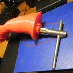
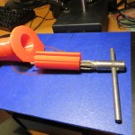
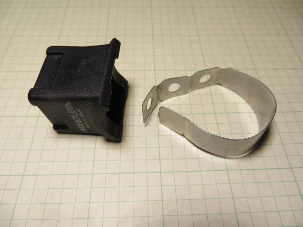
During this project I had been posting results and questions on the ‘PrintrbotTalk’ forum (see this post), and one responder suggested the use of a cheap dial indicator from Harbor Freight to level the bed, independent of Printrbot’s Z-axis probe. After some initial missteps I was able to get one (item #623 on Harbor Freight’s website) and figure out a way to mount it on the extruder carriage. The following photos show the mounting arrangement, using the handy mounting tab on the back of the dial indicator.
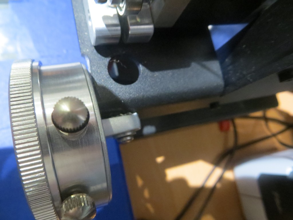
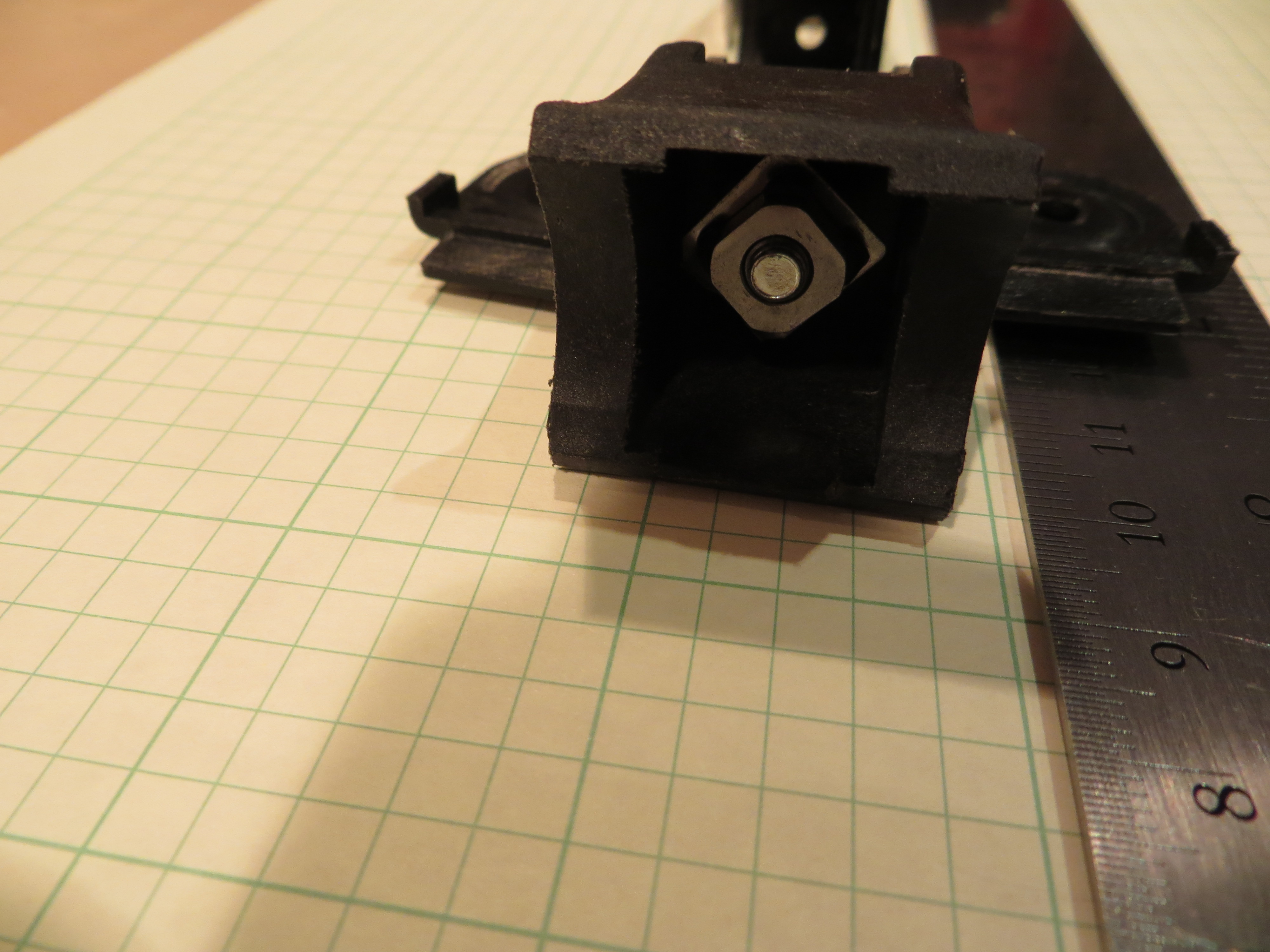
Dial indicator mounted to the extruder carriage. Note ground-down portion of the carriage .
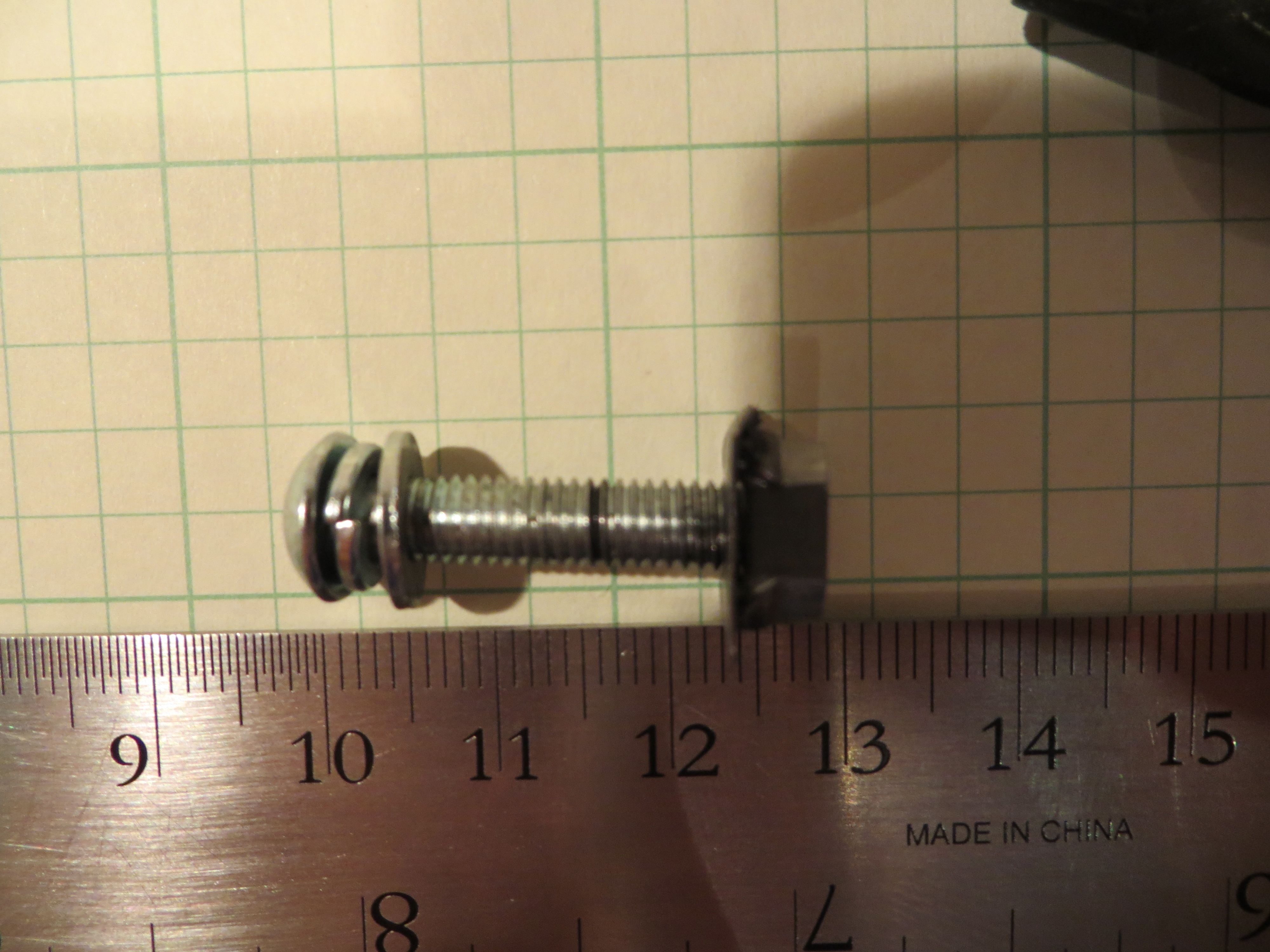
1/4″ by 1/4″ bushing fit nicely inside the 1/4″ I.D. mounting hole.
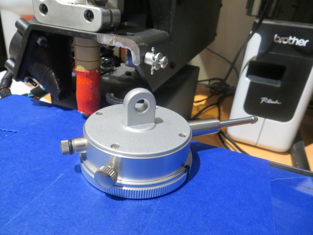
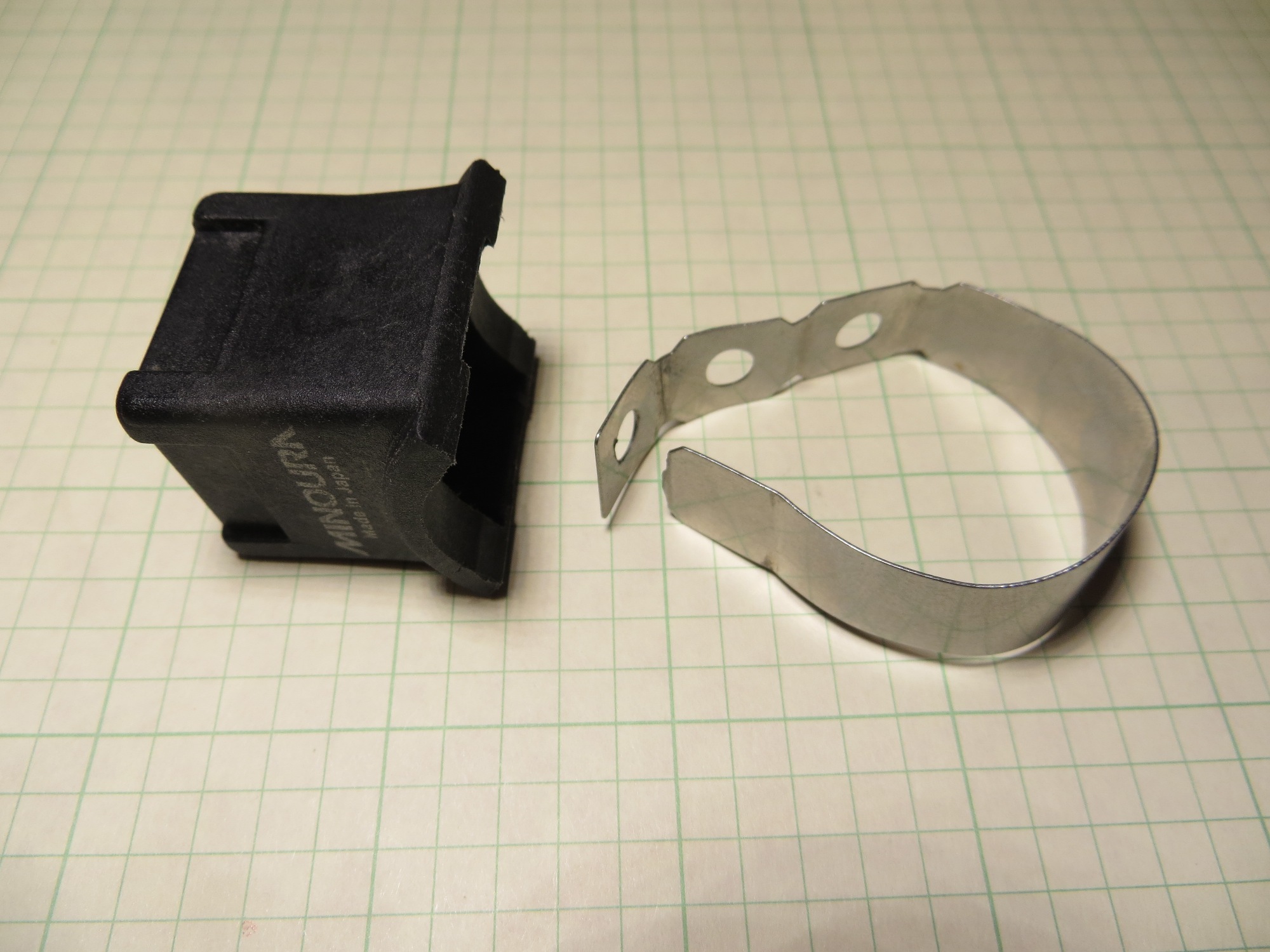
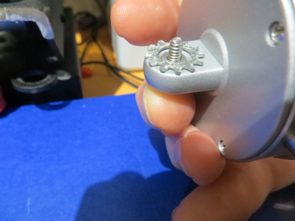
Dial indicator mounting tab and mounting screw/bushing
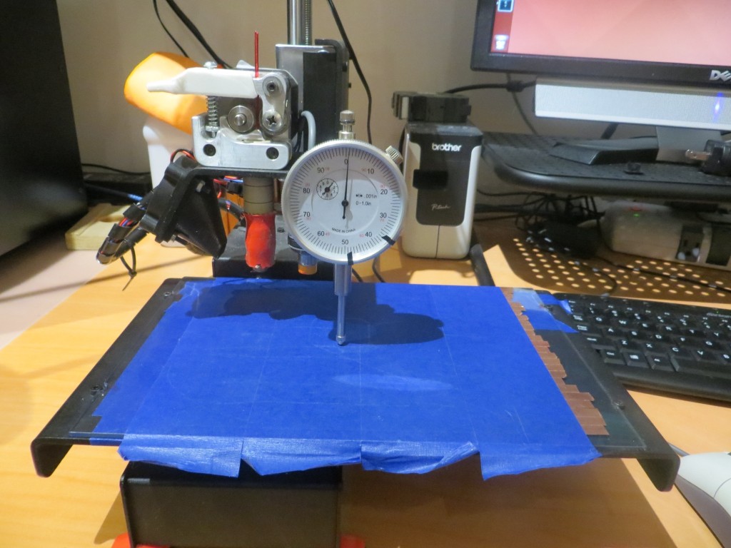
Dial indicator mounted, with carriage height adjusted to achieve a zero reading
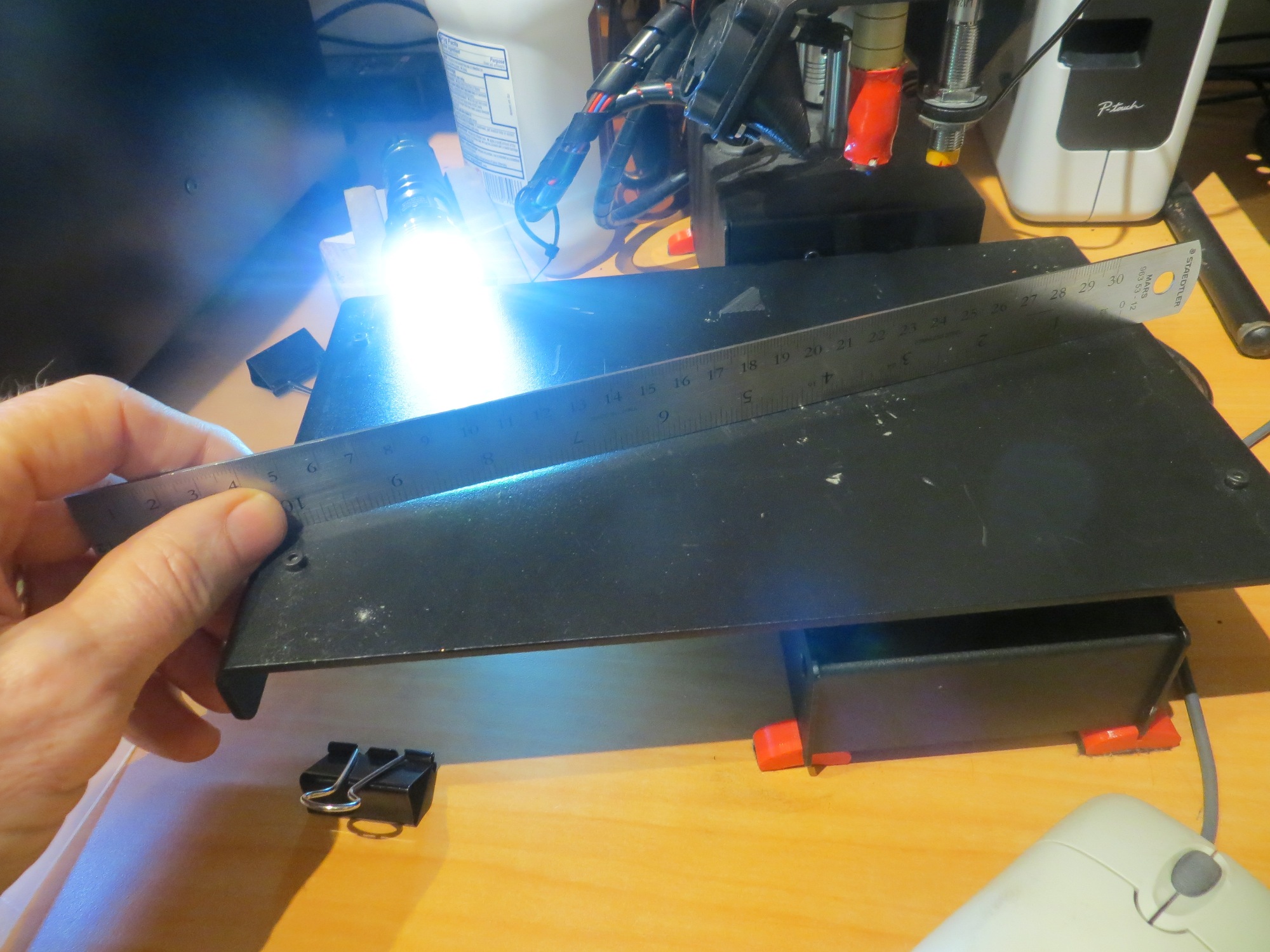
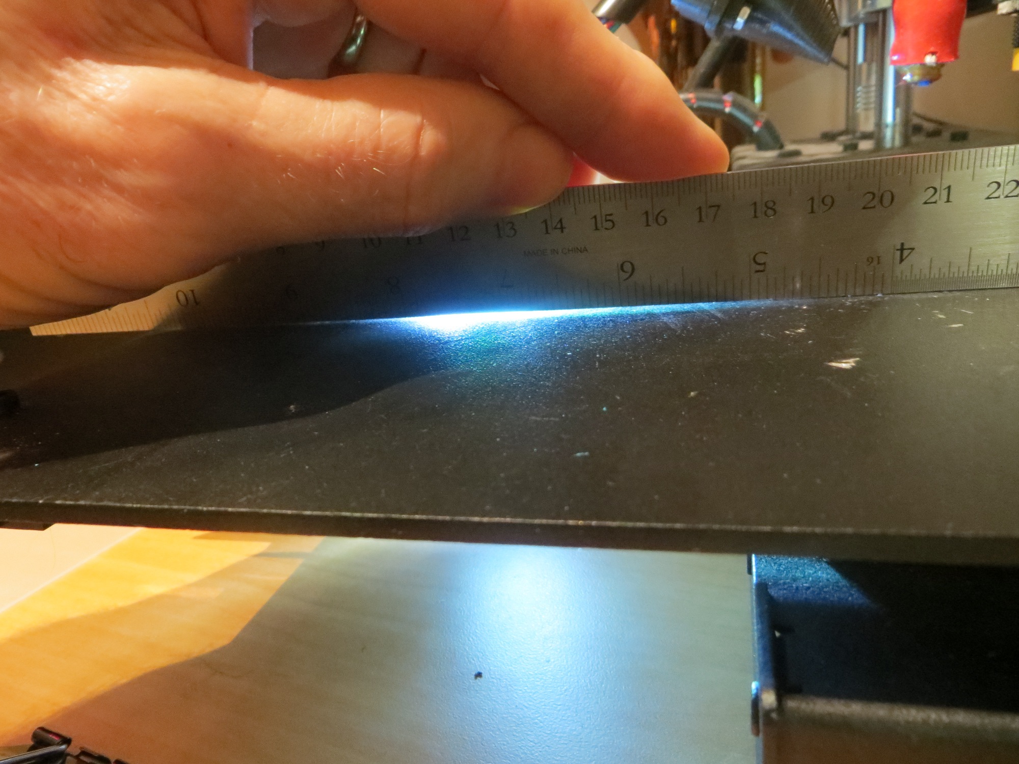
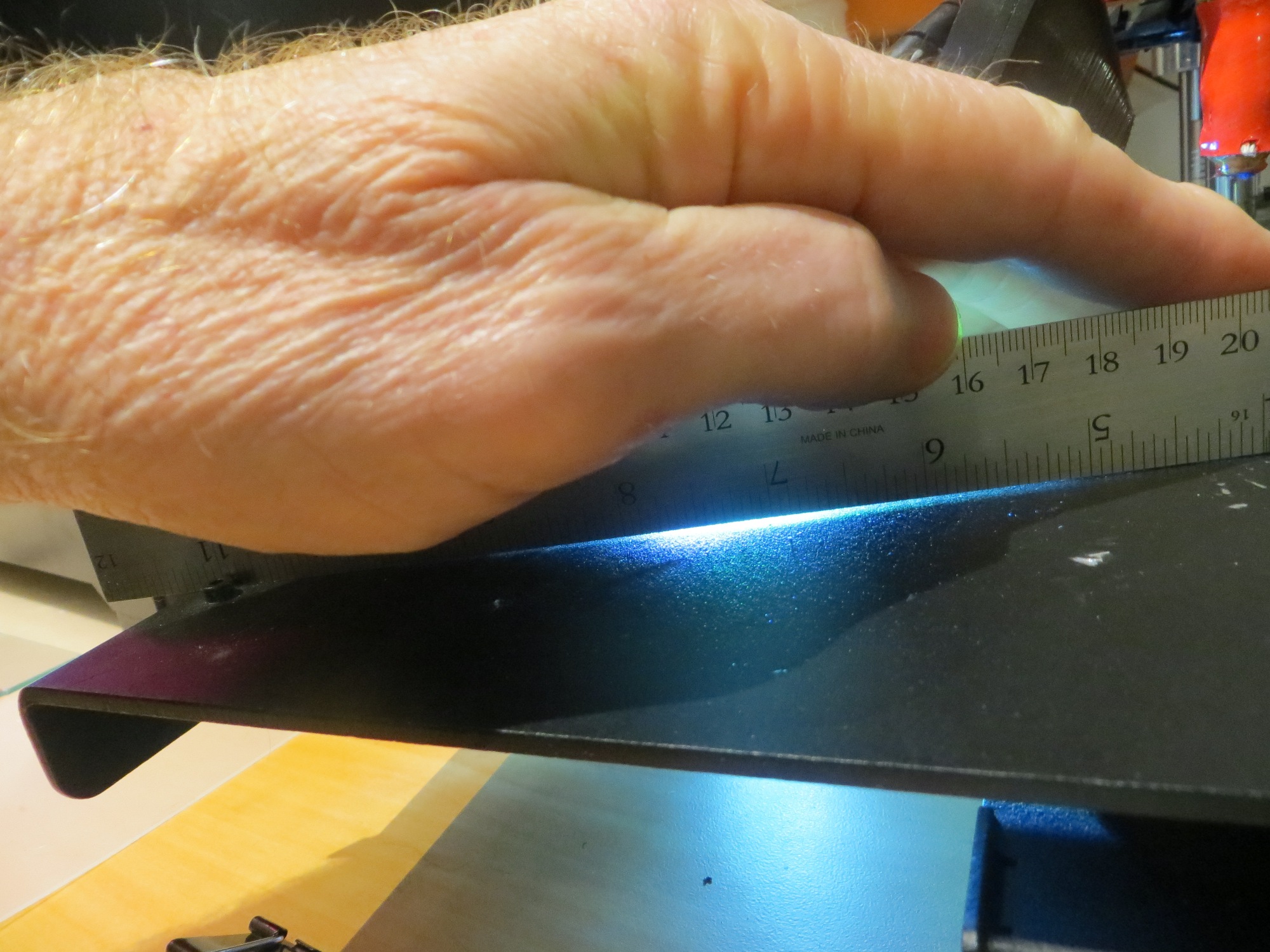
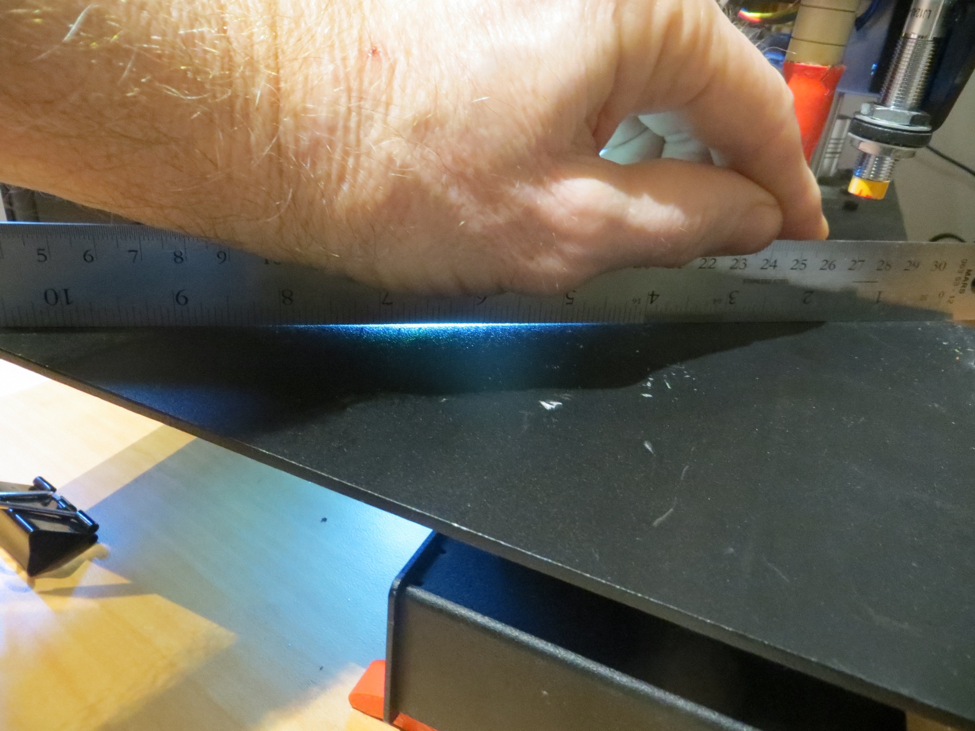
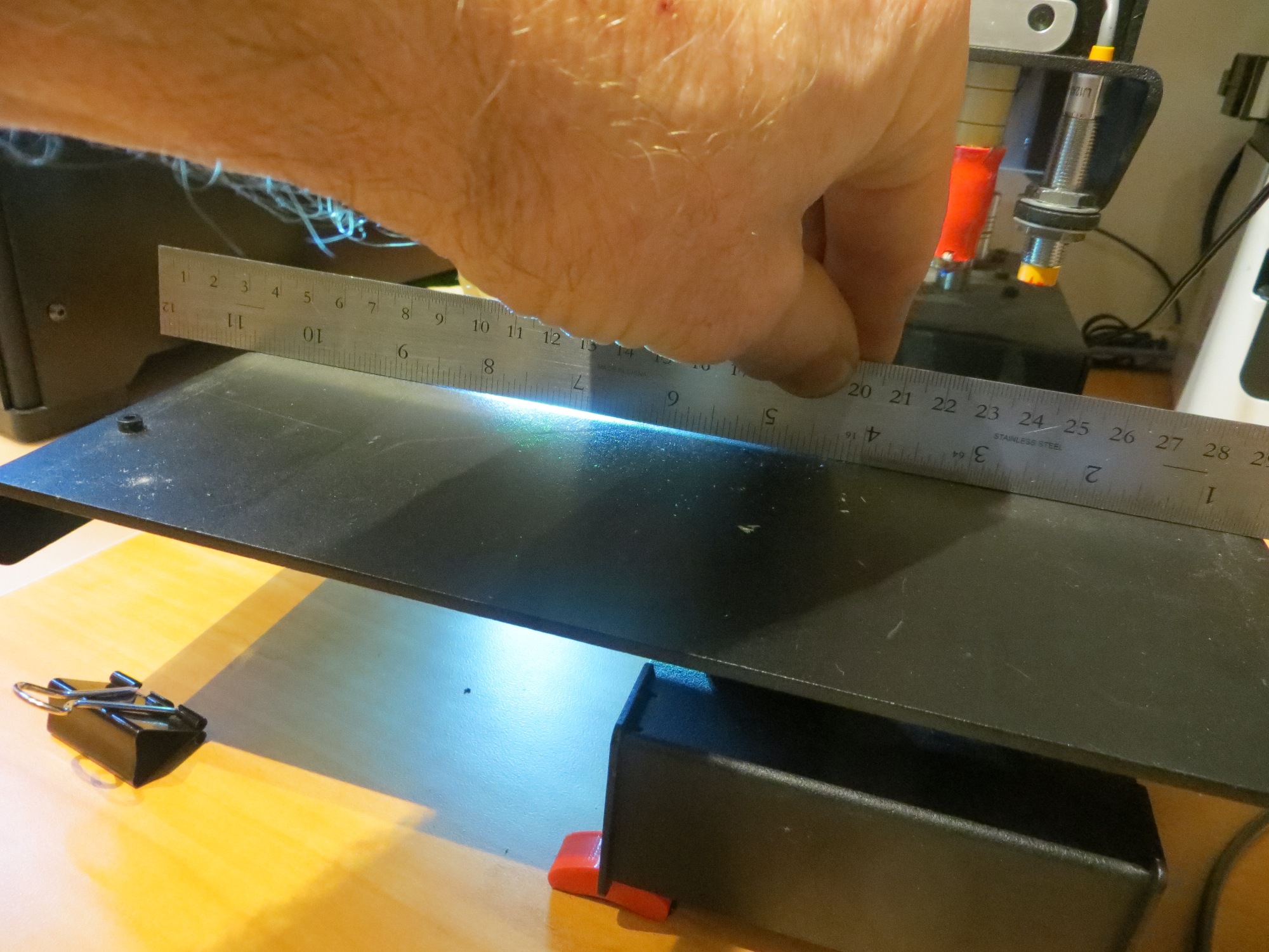
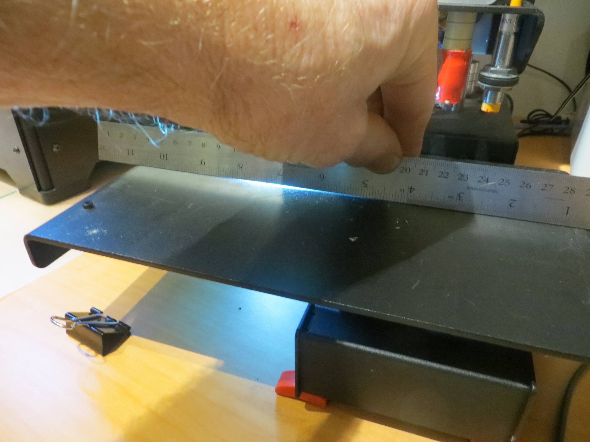
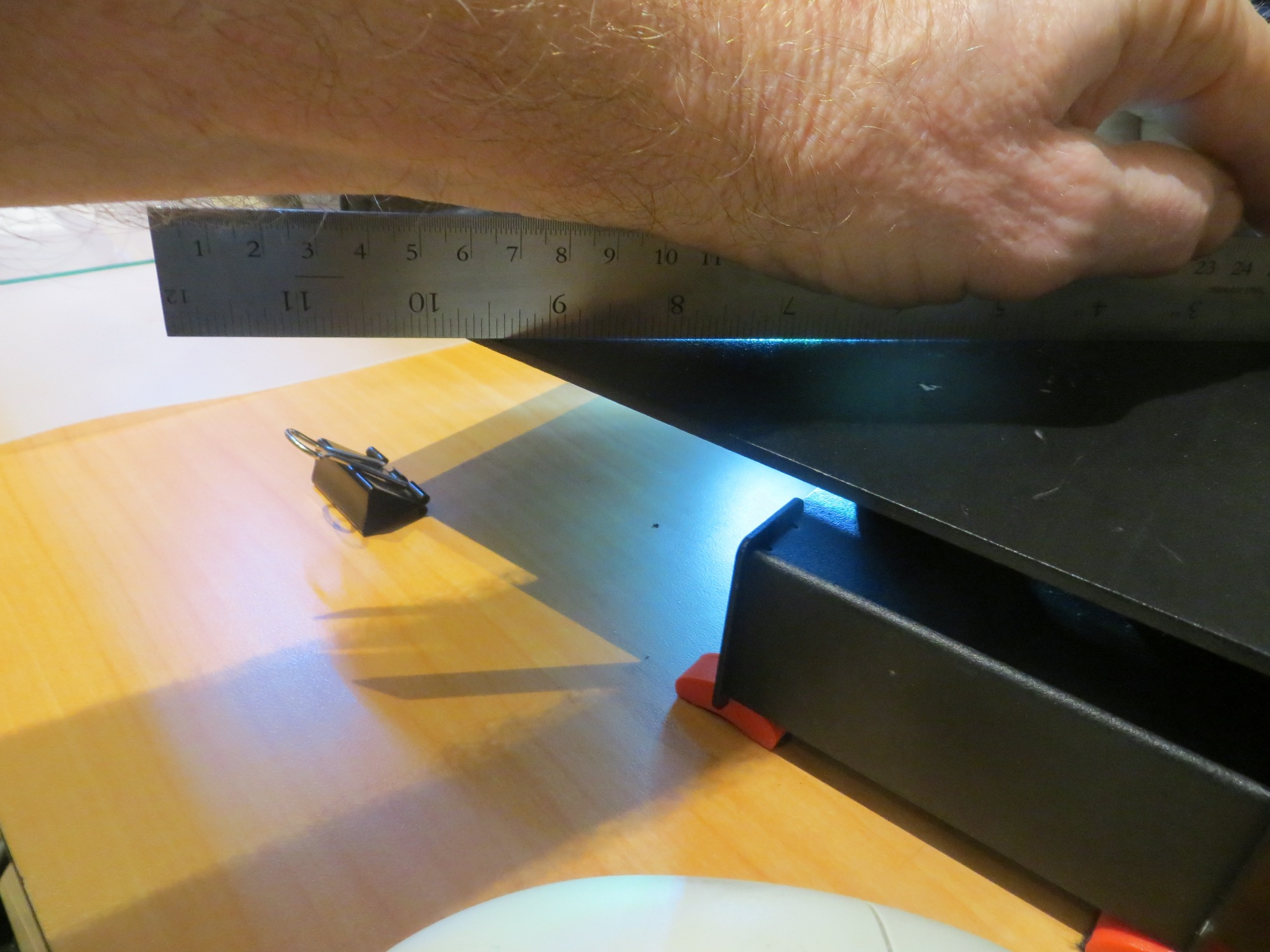
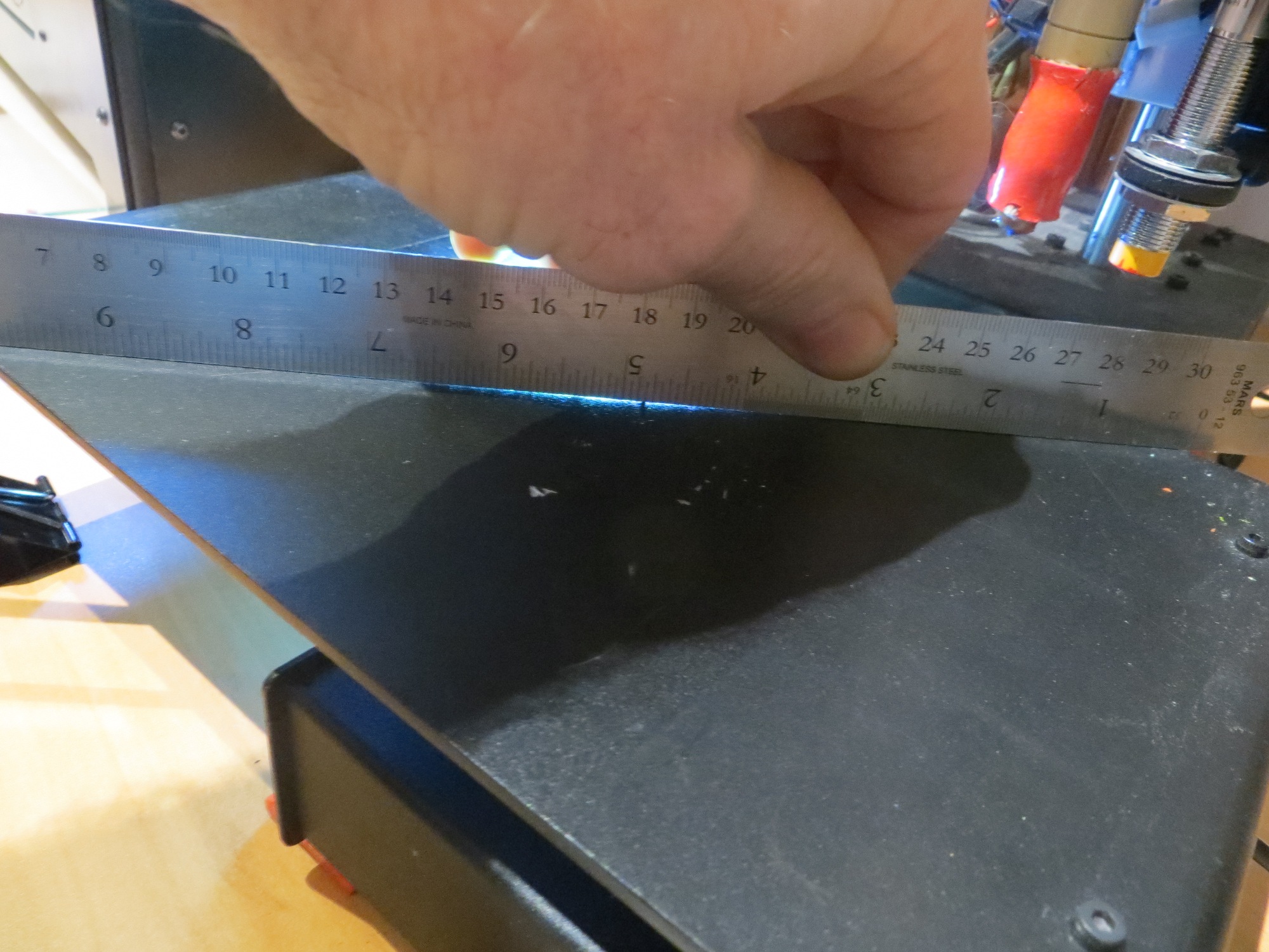
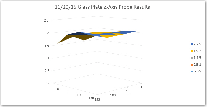
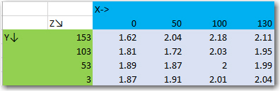
With this arrangement, I was able to simply move the carriage around by hand, noting the needle excursions from zero. Then painter’s tape was added to the low side (or removed from the high side) to minimize the differential across the printing area. A 1mm height difference equates to about 40 small divisions on the indicator, and after shimming I was able to achieve a height differential of +/- 5 small divisions (about 0.125mm) across the print area.
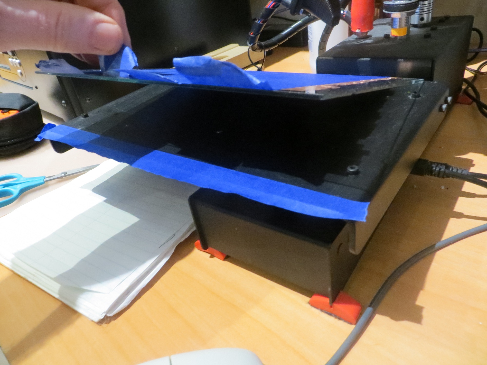
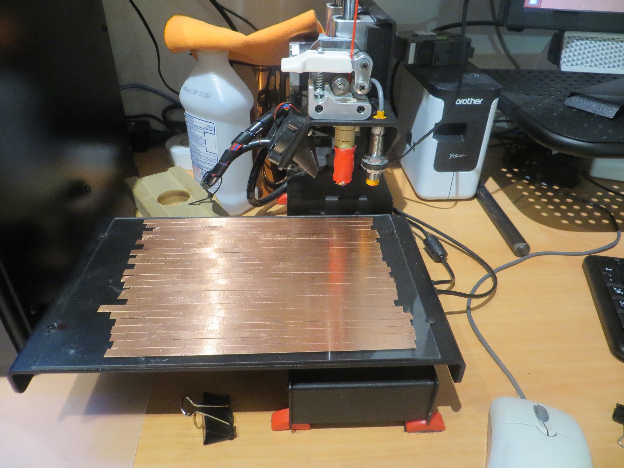
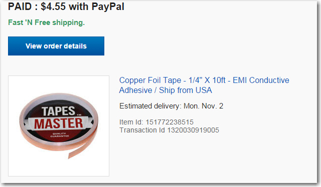
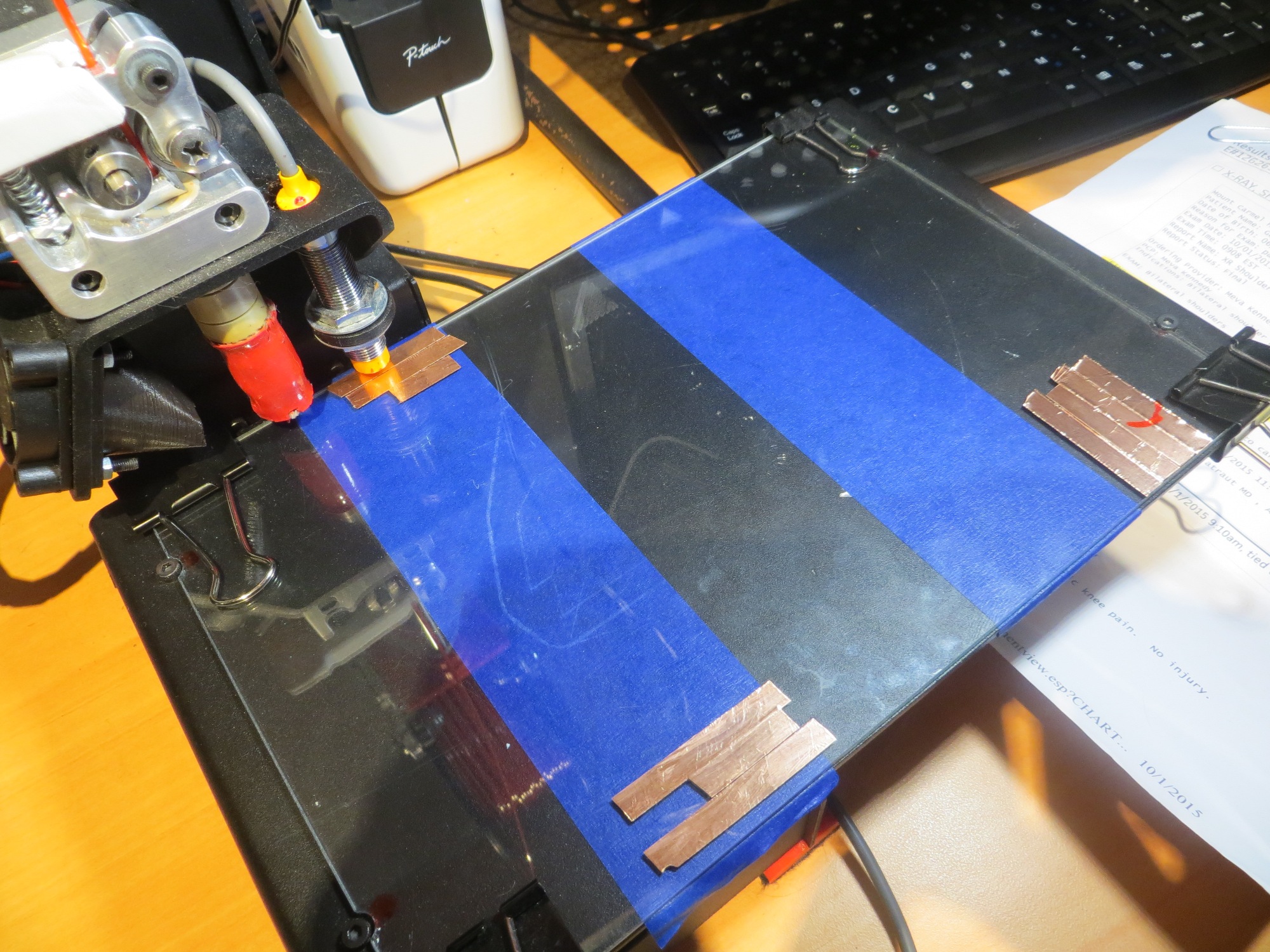
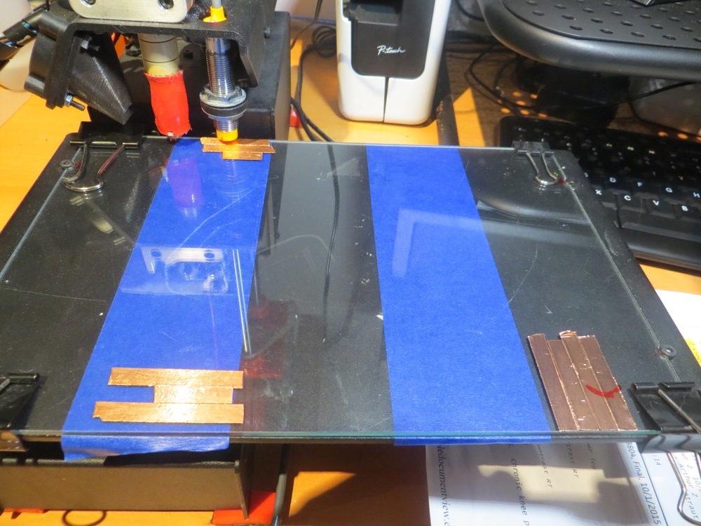
After getting the glass plate all shimmed up, I decided that because I was no longer using the ‘auto-leveling’ (actually more like ’tilt correction’) feature, I could now remove the copper foil layer from beneath the painter’s tape – BIG MISTAKE!! On the very first test print after doing this, I realized to my horror that the Printrbot still needed to find the Z-axis ‘home’ position, and the only way to do that was with the Z-axis metal-sensing probe. Fortunately I was able to pull the power plug before the extruder tip had a chance to shatter my nice new glass plate!
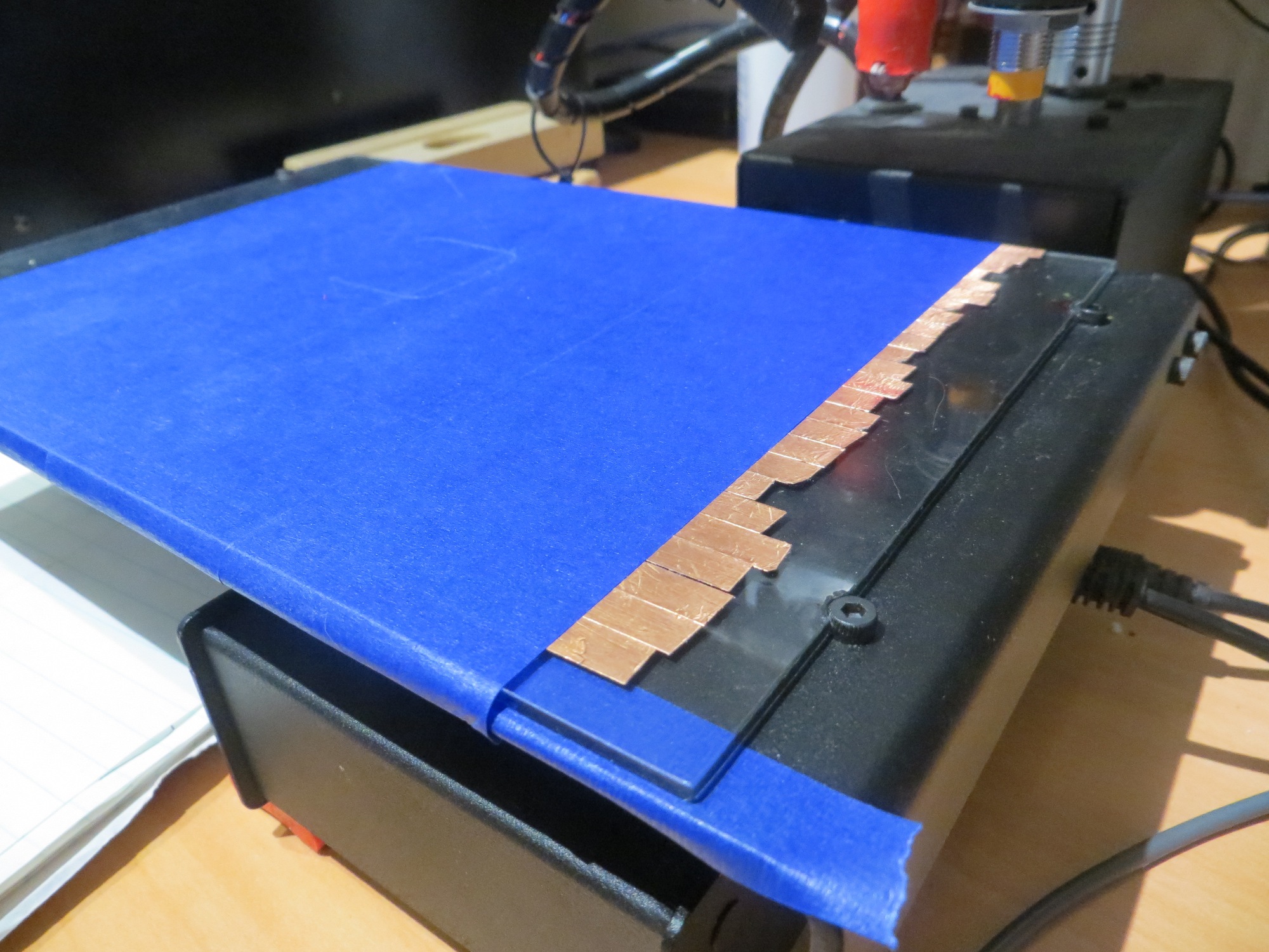
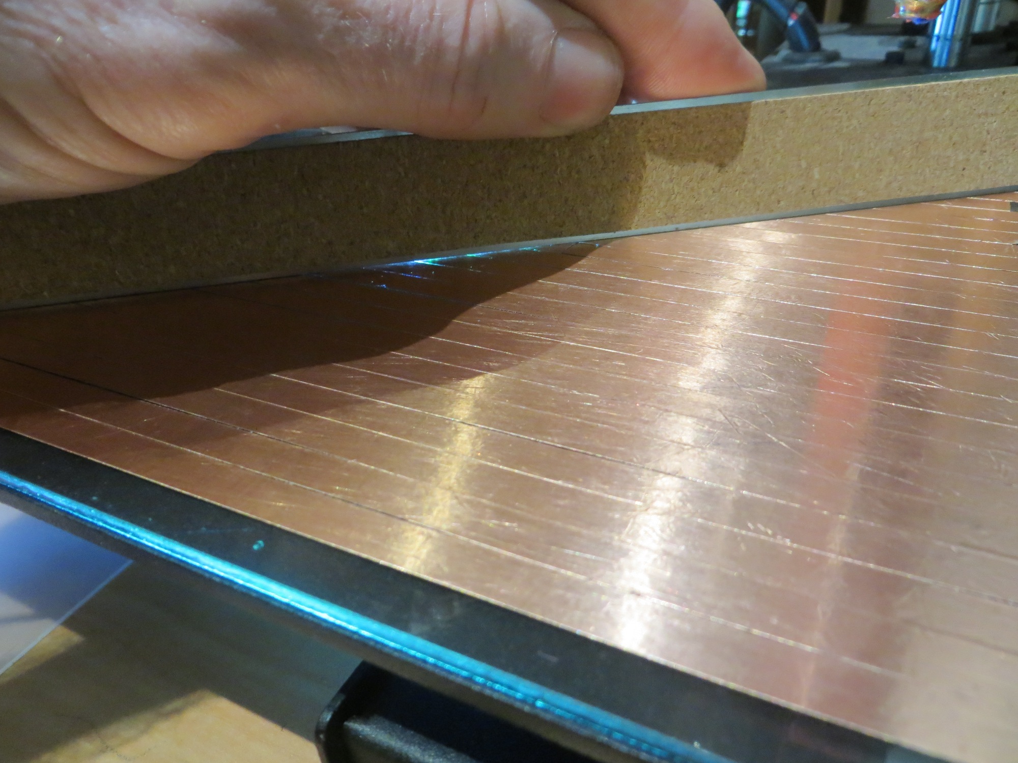
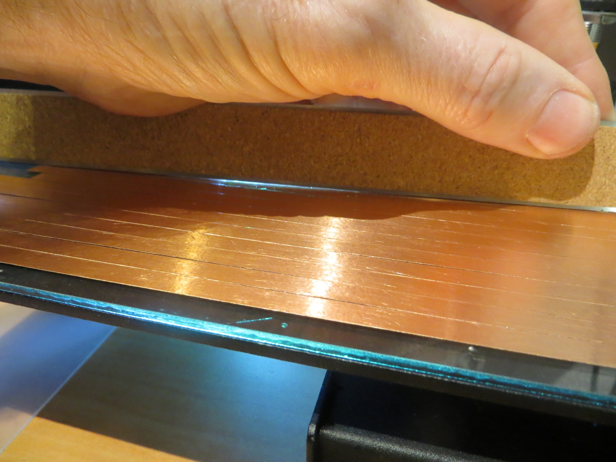
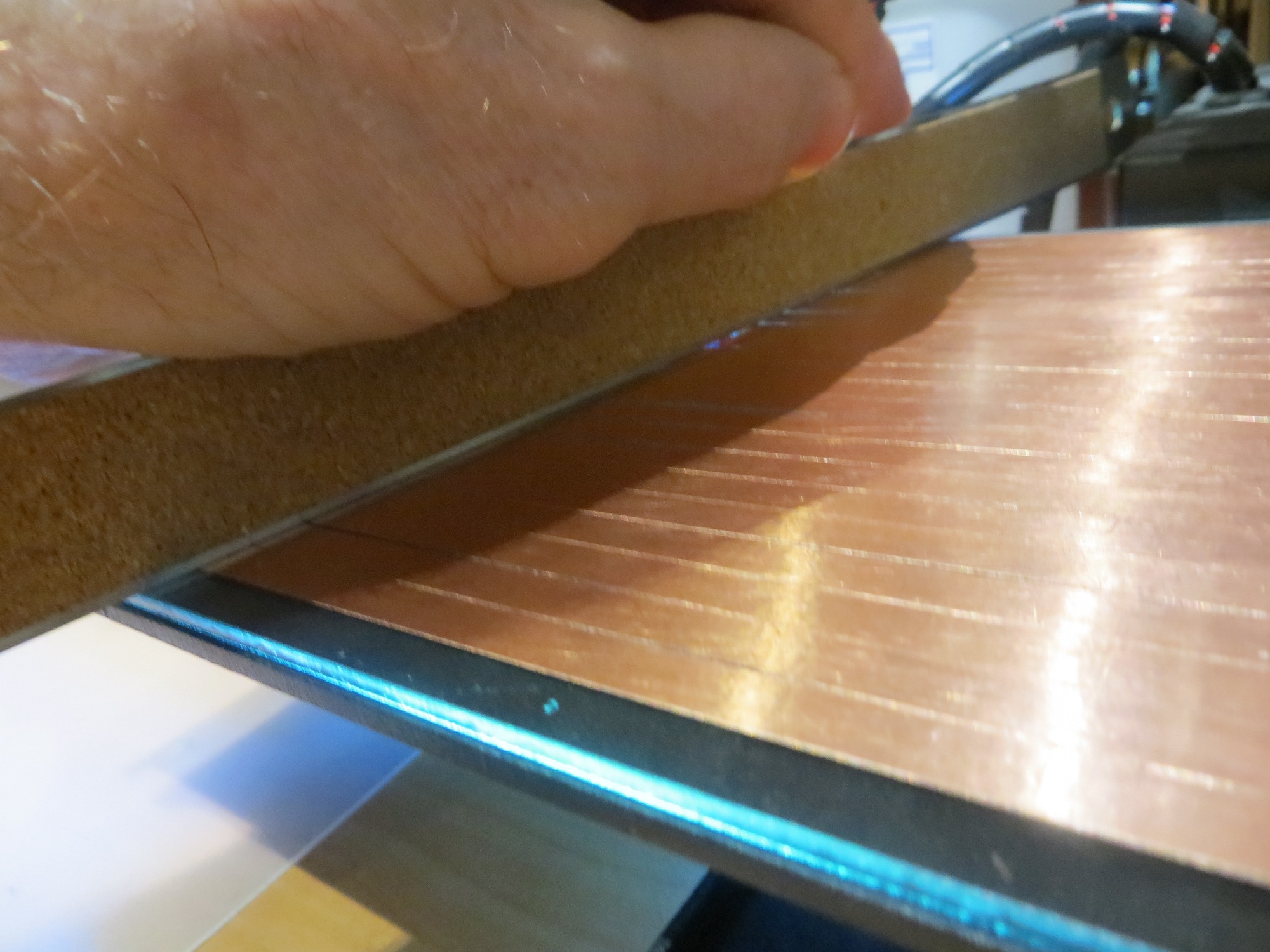
After beating myself up for a while over such a bonehead move, I realized I had just two choices; I could laboriously replace the copper foil layer (one quarter-inch strip at a time), or I would have to find some way of replacing the metal-sensing probe with something else. I did not want to go through the agony of replacing the foil layer, so I was left (I thought) with option 2. Someone on PrinterbotTalk had mentioned a mechanical switch replacement for the Z-axis probe, and said there was at least one Thingiverse design for a bracket that mounted to one of the vertical carriage posts. I took a look at this and decided I could adapt it for one of the normally-open pushbutton switches I had in my electronics parts bins. After some further Googling, I realized that the replacement project might be a bit more involved than I originally thought, as there was an issue with later rev motherboards requiring a pullup resistor and some extra wiring to make the mechanical switch idea work.
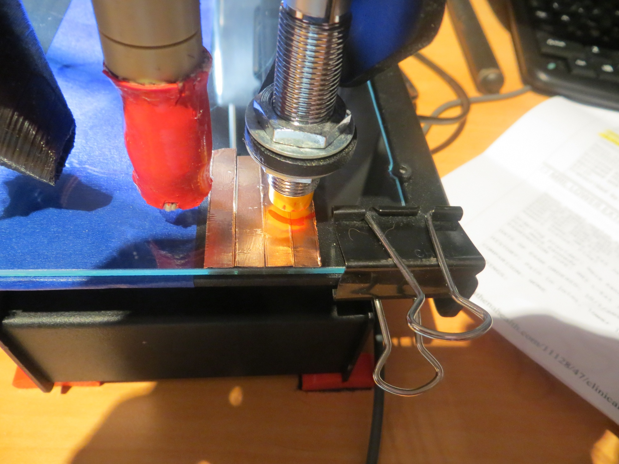
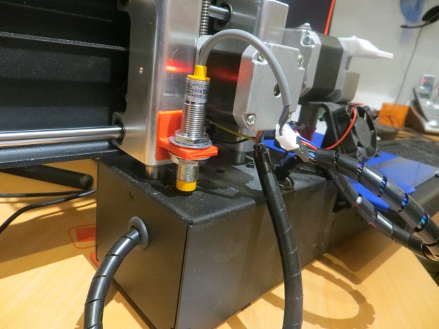
Then I had an uncharacteristically brilliant idea, if I do say so myself. Rather than removing the Z-axis probe and replacing it with a mechanical switch mounted on the vertical slide assembly, why not combine the two ideas and simply mount the Z-axis probe itself on the vertical slide assembly? Then I get the best of both worlds – I don’t have to screw with the wiring at all, and the metal carriage base is perfect for the Z-axis probe to sense – voila!
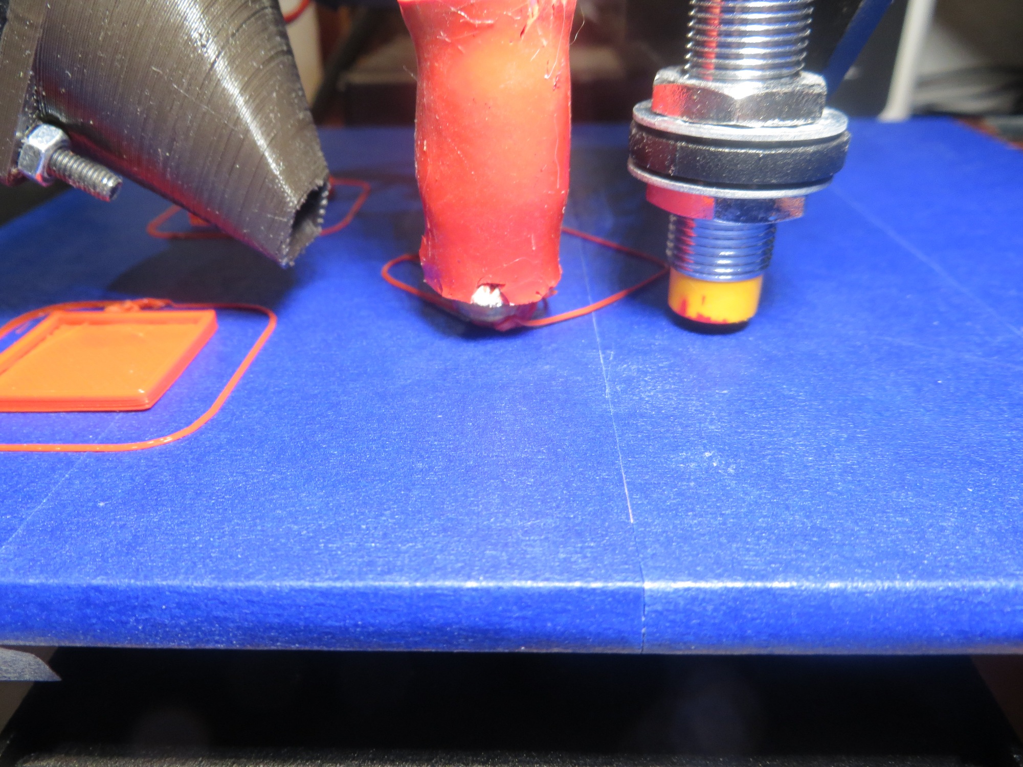
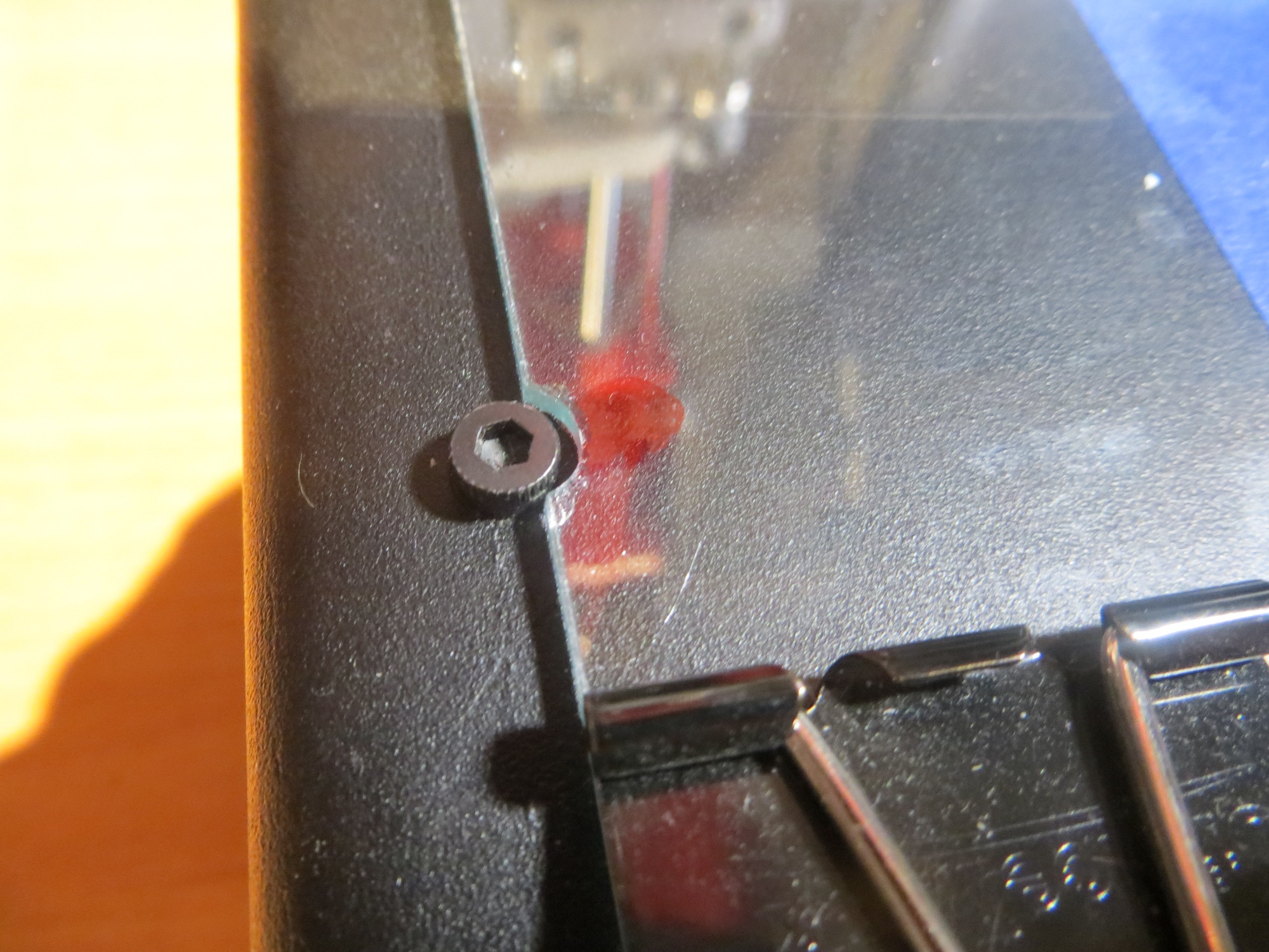
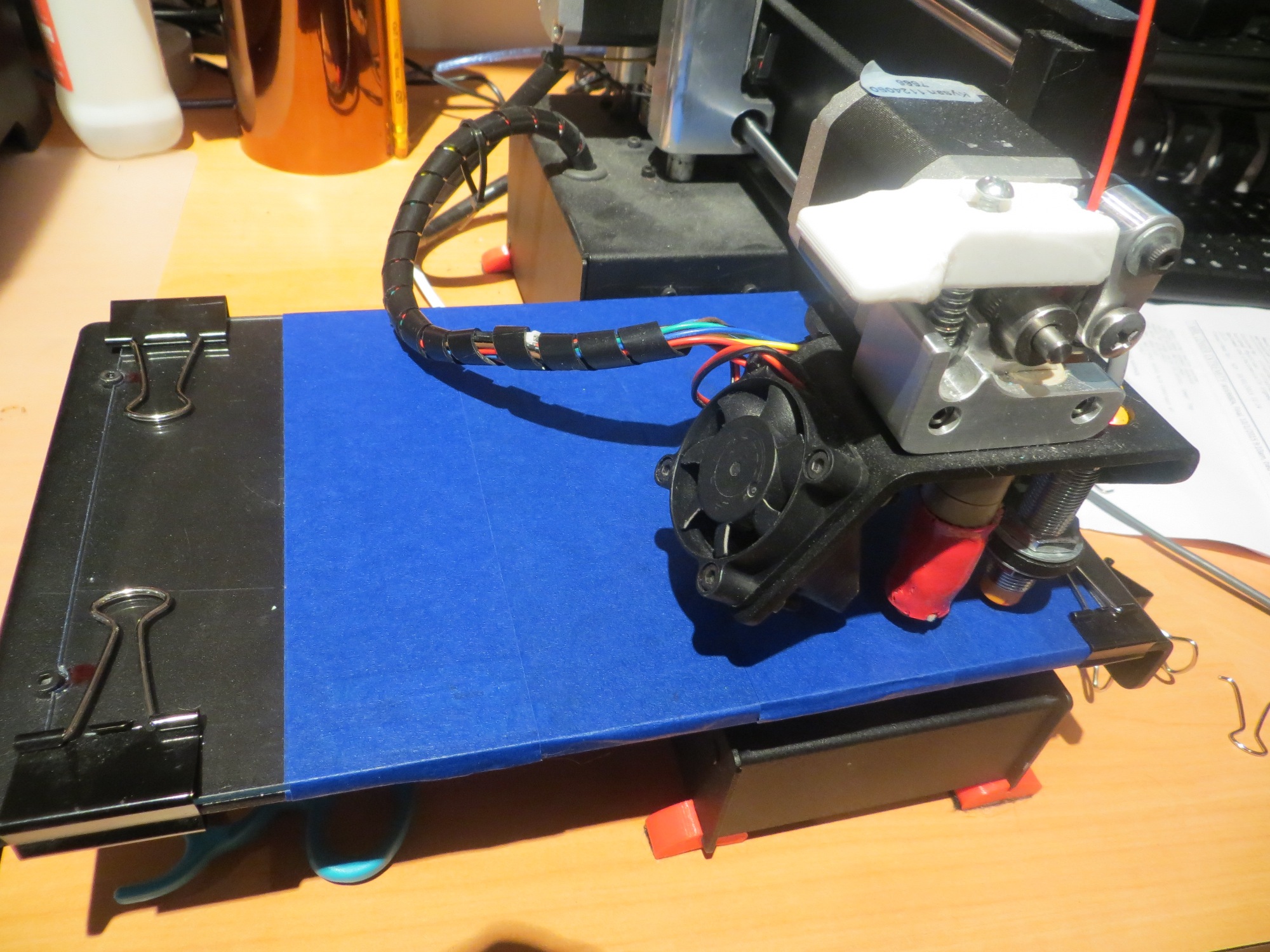
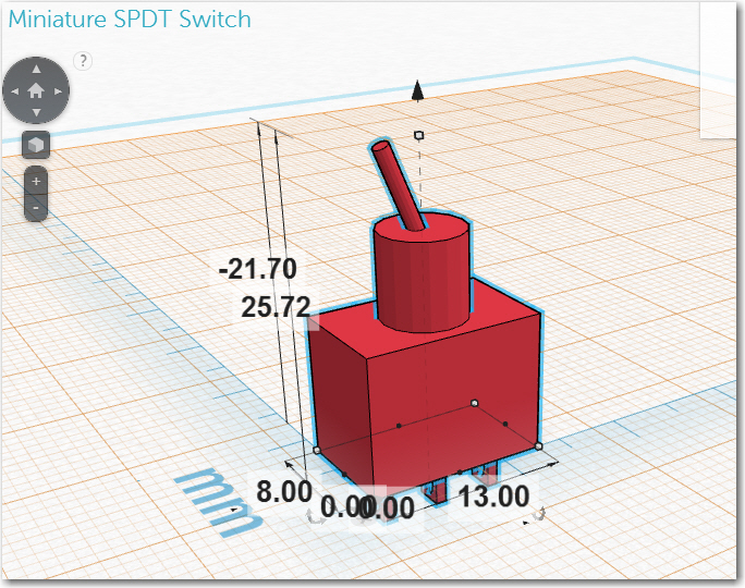
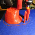
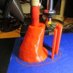
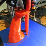
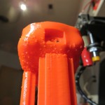
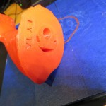
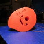
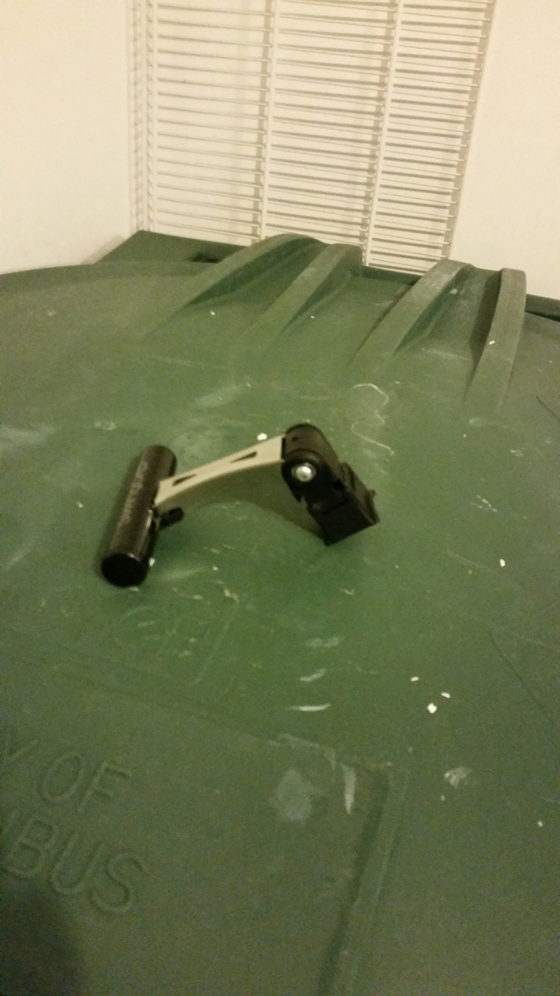
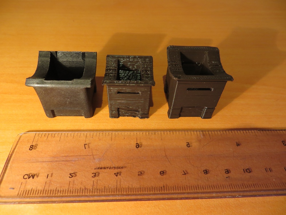
Looking around a bit, I found that if I mounted the probe on the rear vertical slide post bushing, it would have a clear shot at a nice, flat open spot on the carriage base. All I needed was a right-angle bracket to attach the probe to the bushing. A few minutes in TinkerCad produced a printable design, and after a few minutes more I had the bracket printed up (I had to fake the Z-home a bit to get the bracket printed, but who’s counting). I super-glued the bracket to the slide bushing as shown in the following photo, and simply adjusted the height of the probe in the bracket so the extruder just ‘grabbed’ a sheet of printer paper when the Z axis was ‘homed’.
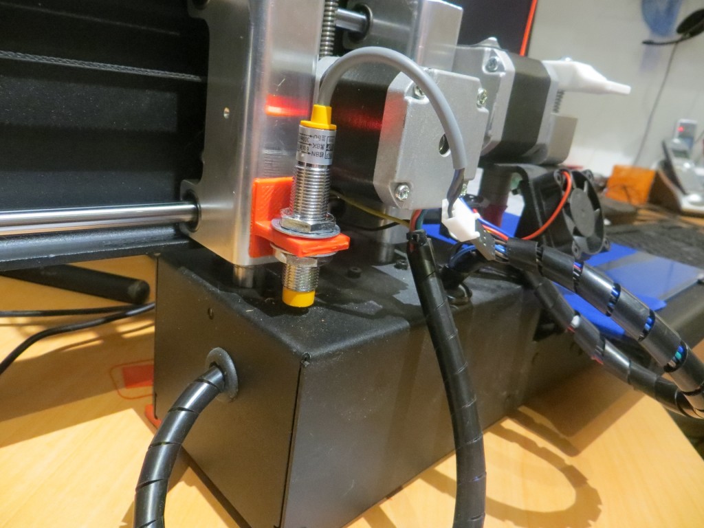
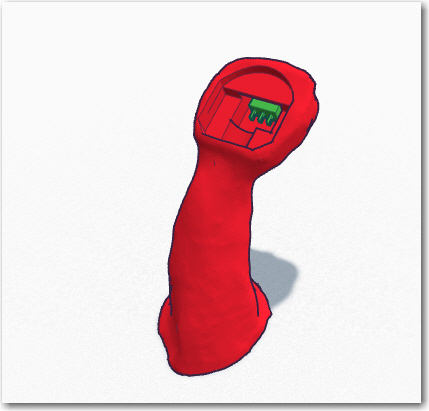
Z-axis probe relocated to the rear vertical post bushing
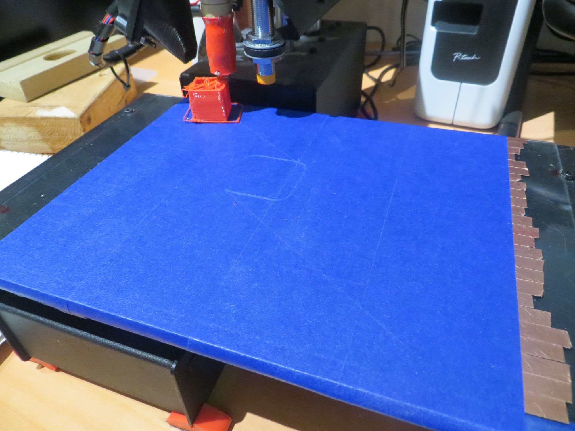
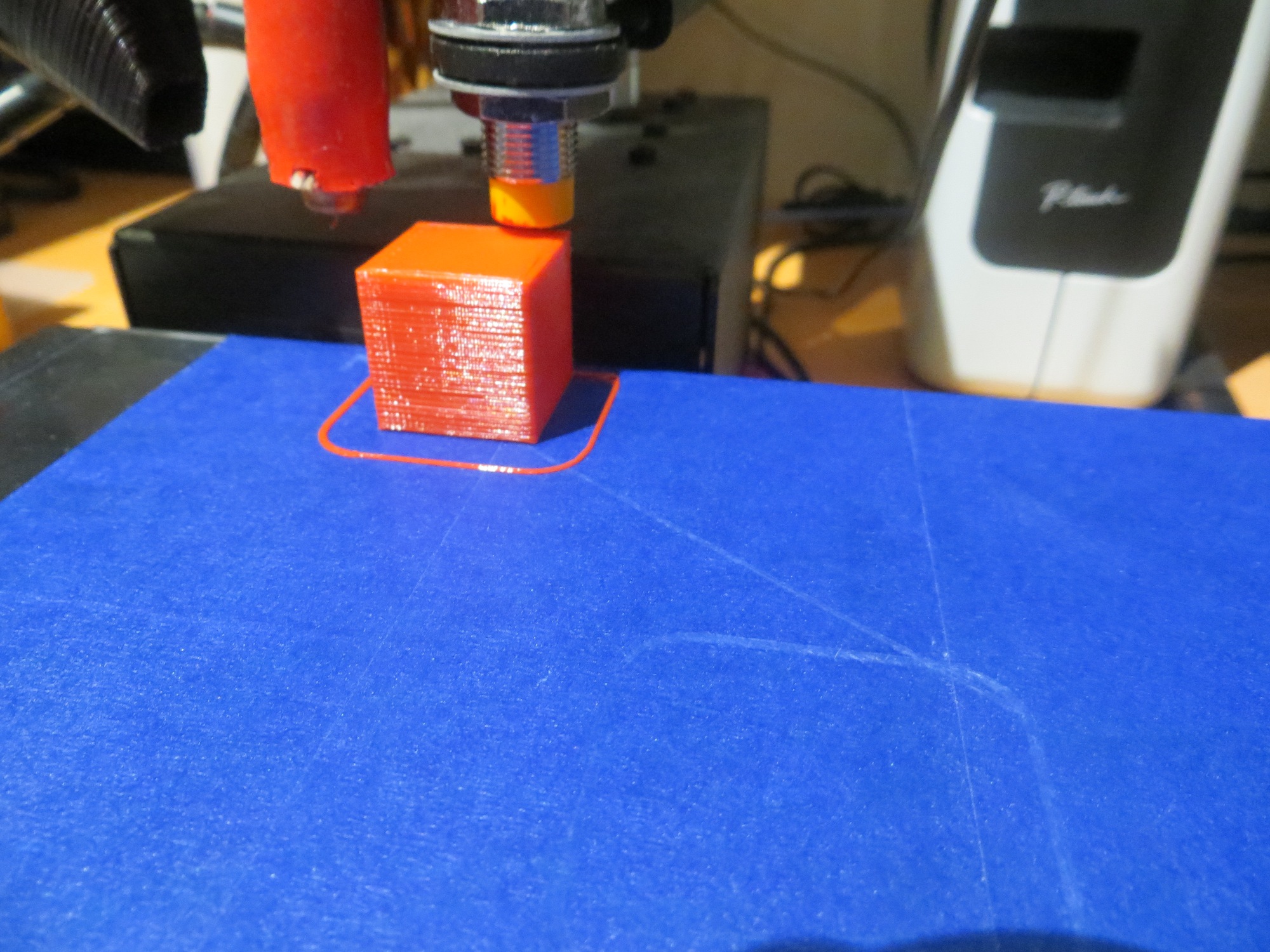
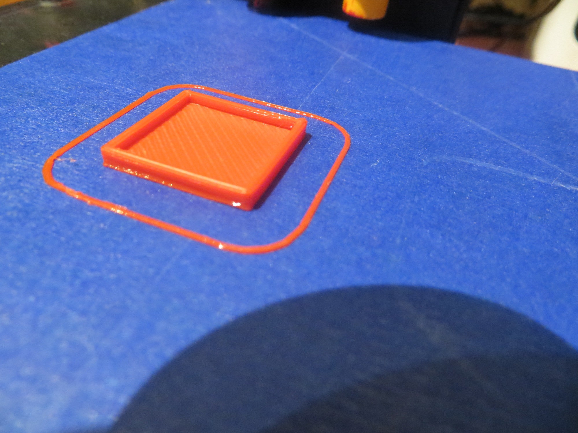
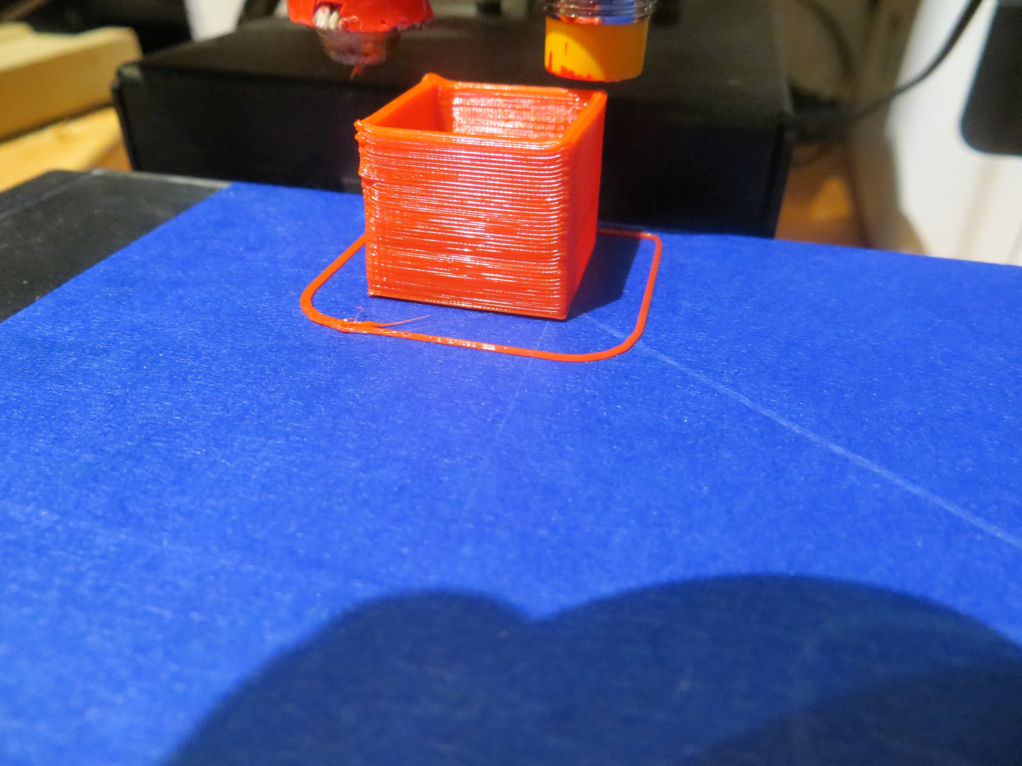
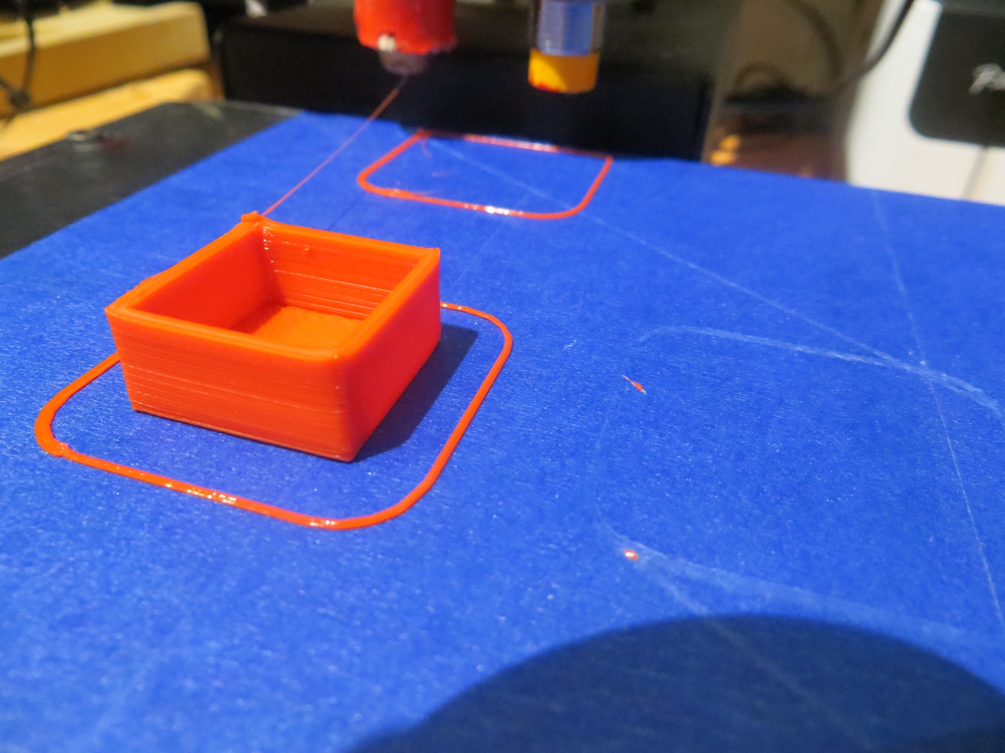
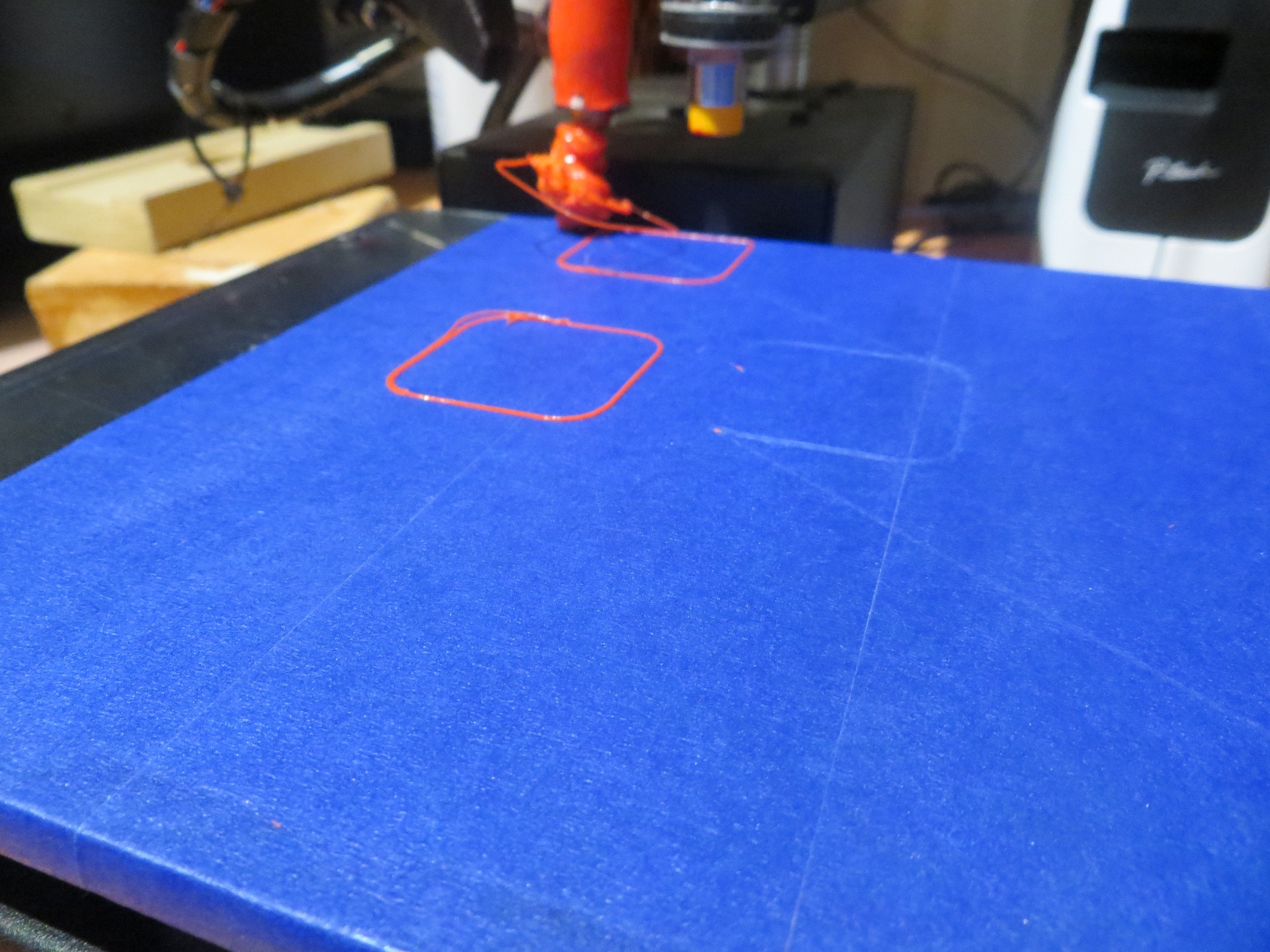
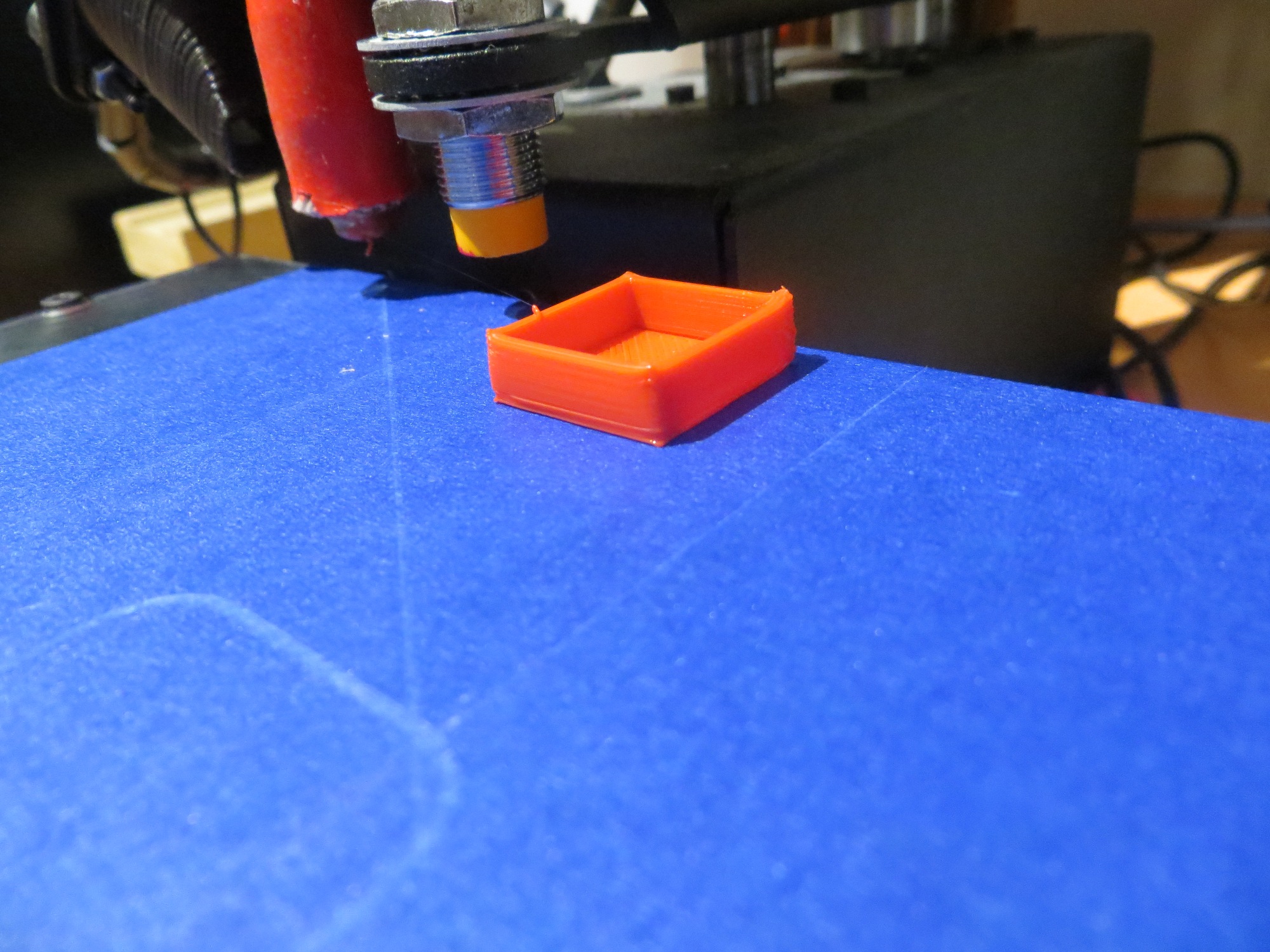
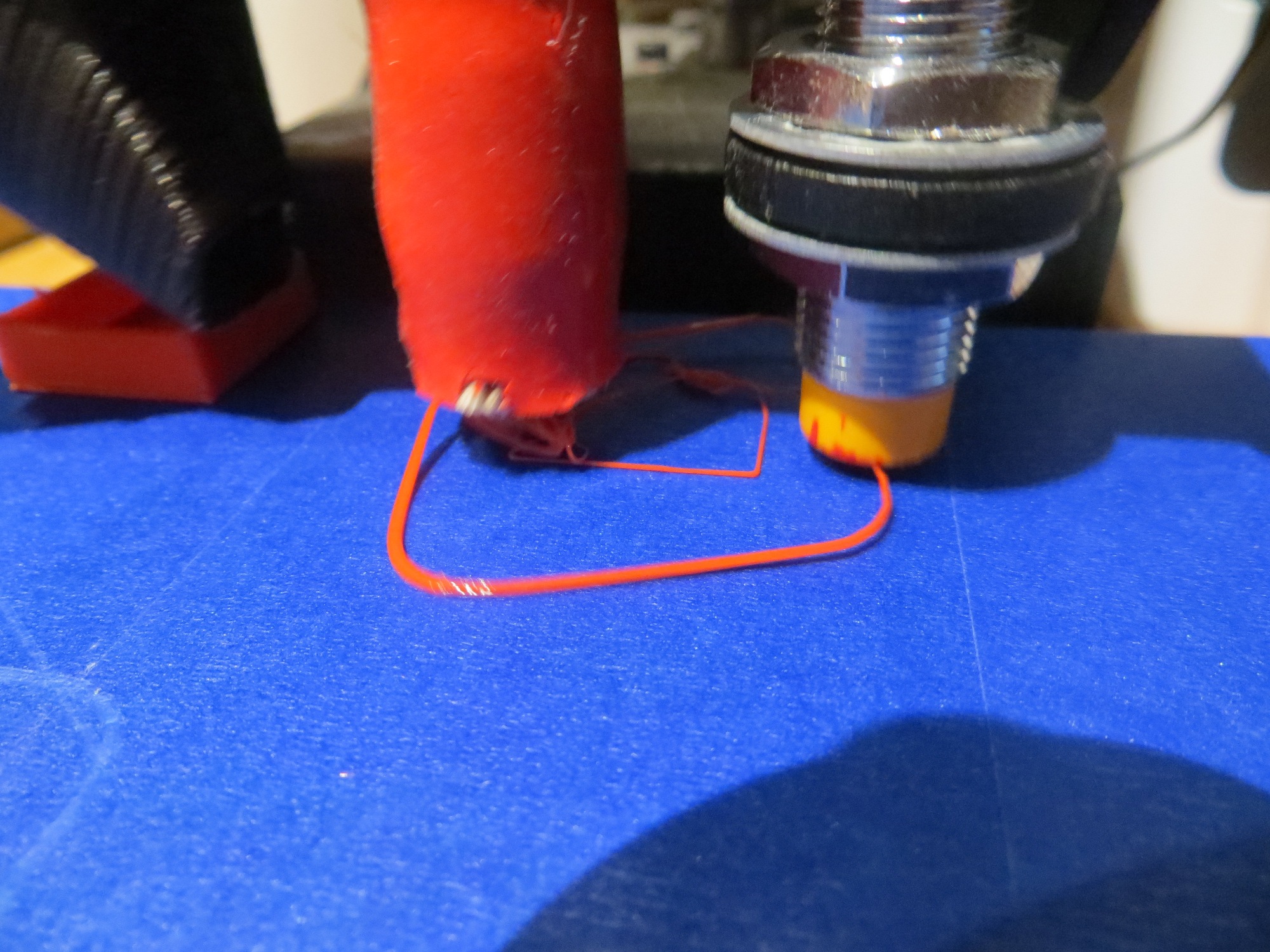
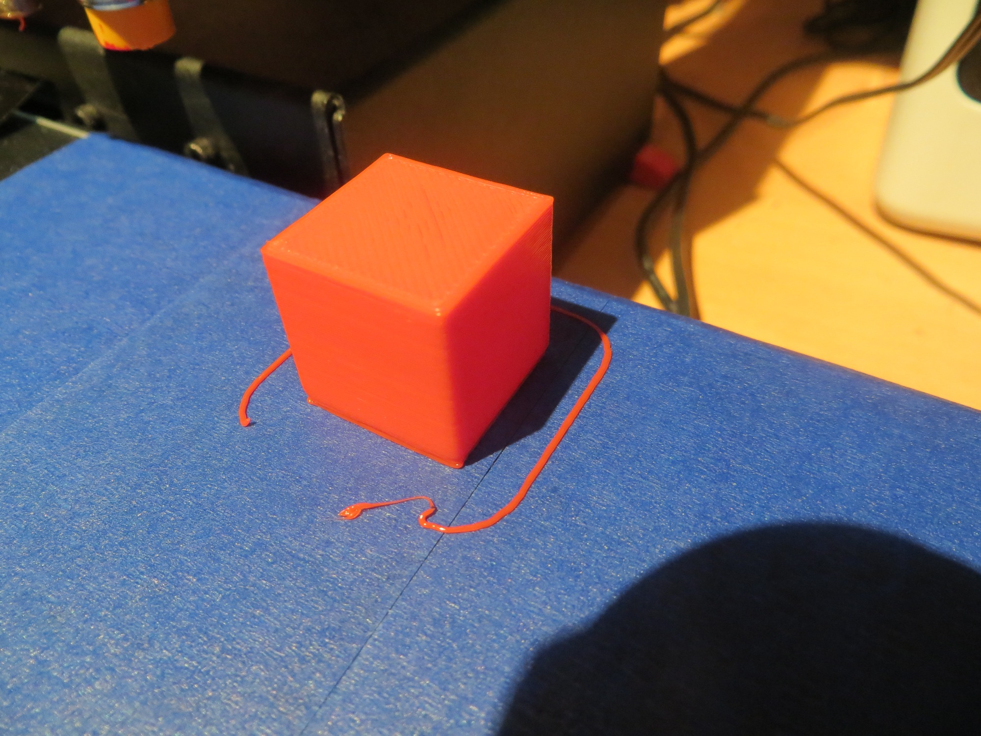
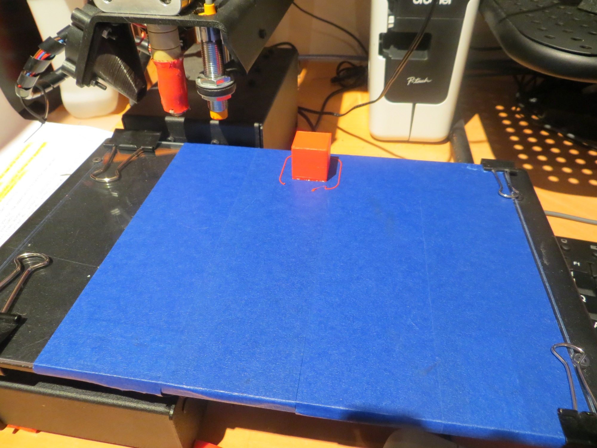
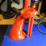
OK, so now I have a really cool glass print bed, with no ugly copper foil layer, and the Printerbot is no longer trying to murder my glass plate. I’ve only done a couple of test prints so far, mostly to figure out what M212 offset is required now with all the changes. However, I am looking forward to consistent prints with the new setup.
Stay tuned!
Frank