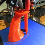
The title of my last post on this subject had the word ‘Finished?’ with a question mark, because I suspected that John and I weren’t really ‘finished’ with this project (and for that matter, may never be!), and sure ’nuff, the ‘finished’ version came back to me with some suggestions for improvements. However, as has happened at every stage of this journey, lessons learned with each trial opened up avenues for improvement. One of the many cool things about the current 3D printing world is that a single individual or a small group (in our case, a ‘group’ of two!) can traverse the complete trial, re-design and re-implement cycle in a very short time at essentially zero cost. This short cycle time and low incremental cost means that failure isn’t only an option – it’s an expected and accepted way of rapidly stepping through many design variations in the quest for truly useful and cool ‘things’. After all, who would have thought that a clay model of a joystick-mounted ClearNav remote caddy created by one pilot long ago would have evolved so rapidly into a detachable and rotatable flap handle mounted caddy at all, much less in the 2-3 months we have been working on the project (and this time includes several ship/return cycles to move trial pieces from my lab to John’s glider and back again!).
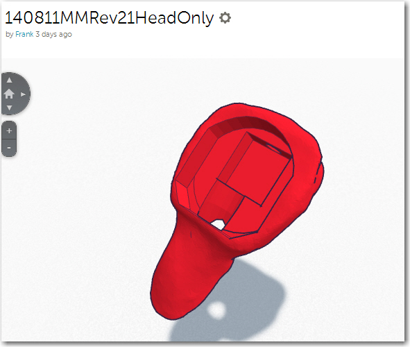
So, anyway, back to the current design cycle: At the conclusion of last week’s episode, I had completed a new version and sent it off to John for testing. This version included the following improvements:
- Deleted the cable channel in the flap grip piece
- Resized the rectangular slot in the flap grip piece
- Removed the finger scallops on the front of the grip
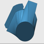
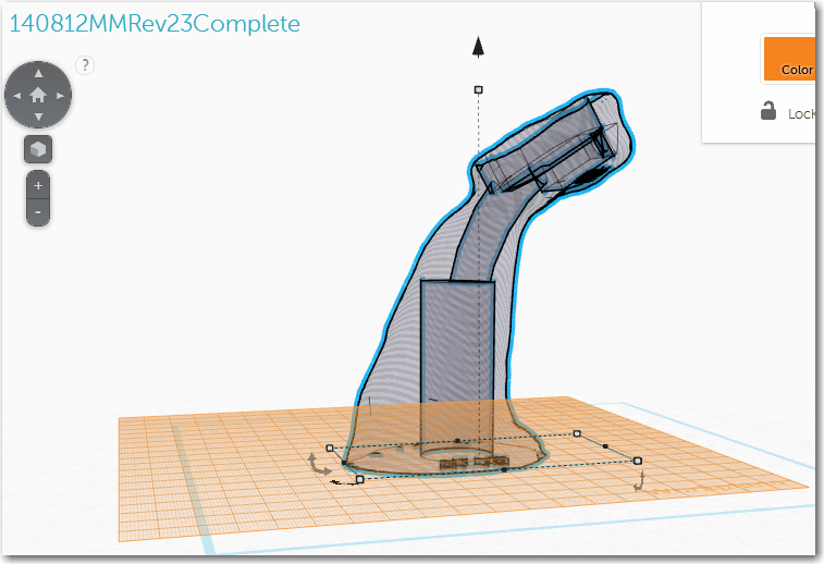
- Offset the caddy piece slightly forward of the flap handle centerline, and rotated it about 20 degrees up’ relative to the top surface of the flap grip
- Used a round vs rectangular post to couple the caddy to the flap grip to allow for rotation
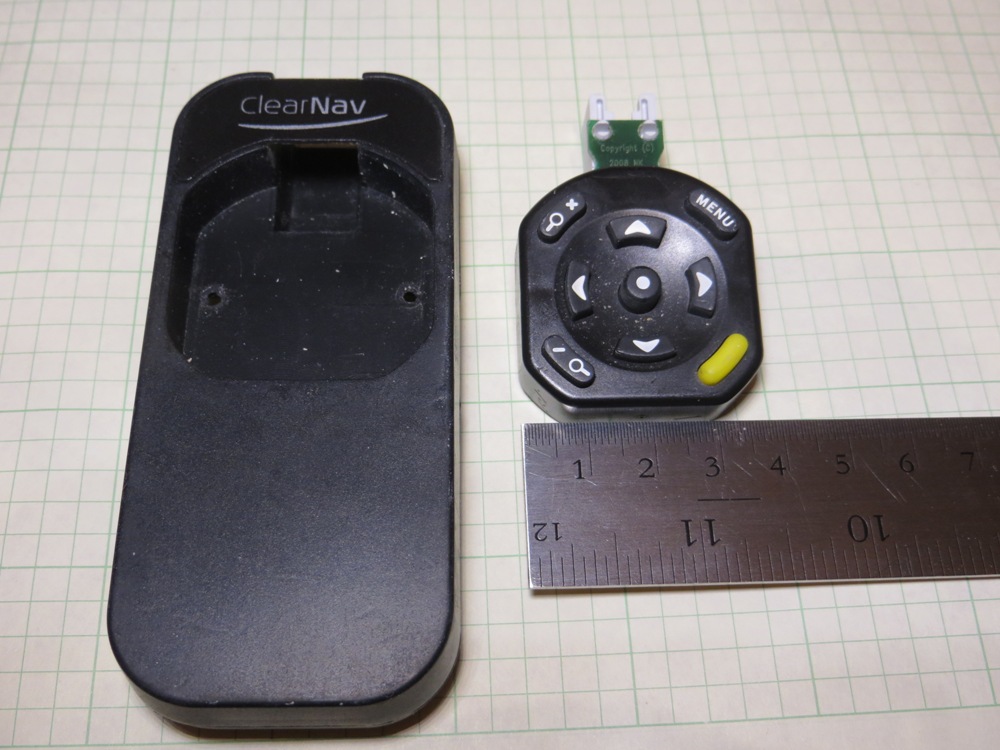
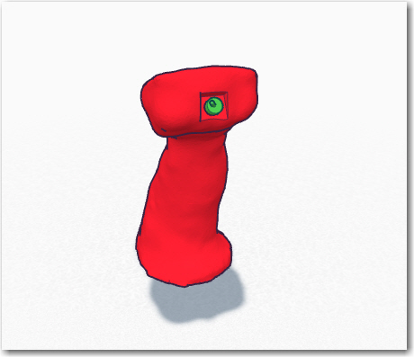
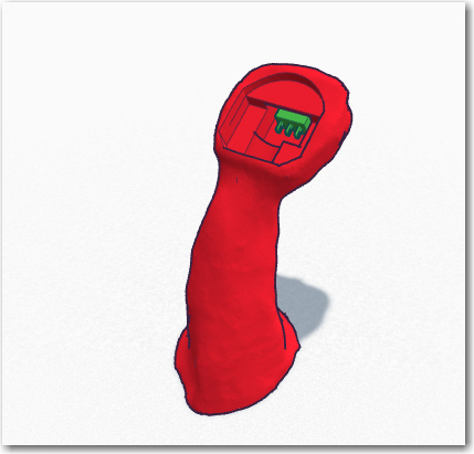
- Added protection walls for the RJ-11 remote connector
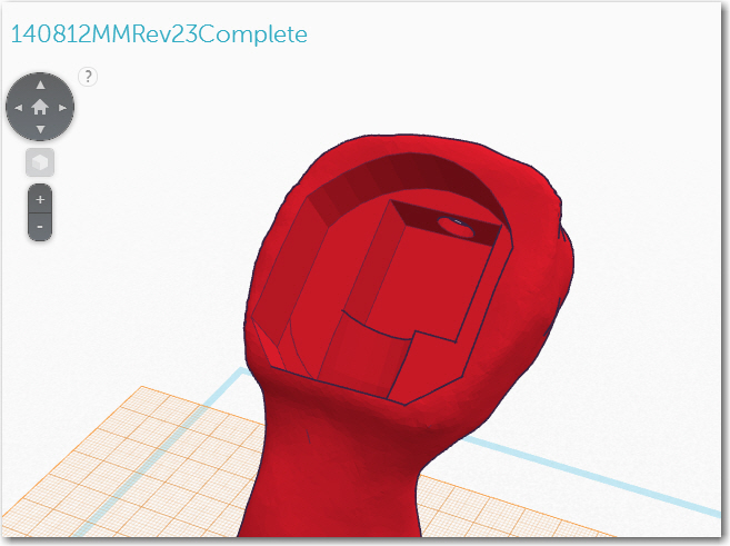
Although this version was a decided improvement over the last one, I still wasn’t happy with it, for a number of reasons:
- First and foremost – the way that I had implemented the rotation feature meant that John could no longer remove just the caddy portion from the flap grip when entering/exiting; now he had to remove the entire system, flap grip and all, from the flap control bar. I didn’t think this would work as a long-term solution.
- The transition piece from the flap grip ellipse to the remote caddy rounded rectangle was clunky and ugly, to say the least
So, even as the previous version was on its way down to John, I was already working on ideas for the next version to address the above issues.
Rotatable and Detachable:
I wanted a way to have my cake and eat it too – a way to make the remote caddy easily (and repeatedly) detachable from the flap grip and easily rotatable about the axis of the flap grip and fixable at the desired rotation angle. Whatever solution I came up with had to also be implementable as a plastic 3D-printable shape – no cheating allowed!
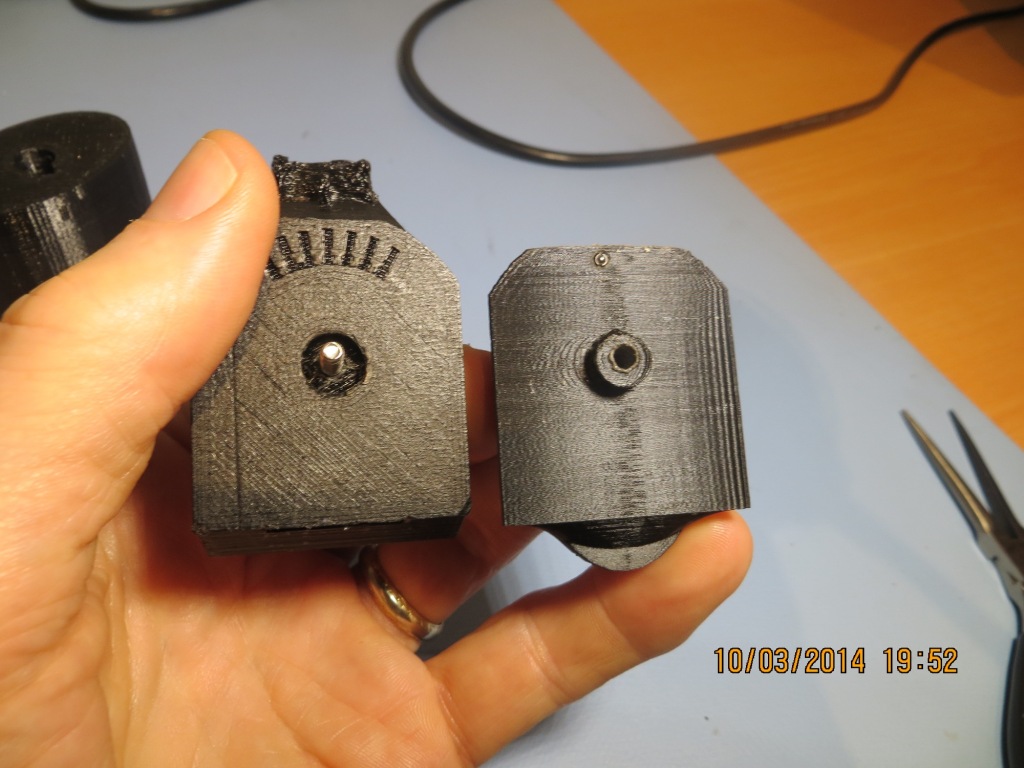
Option 1 – Snap Ring: Maybe I could design a snap ring setup, where the post on the bottom of the caddy piece would snap into some sort of groove in the flap grip so it would rotate freely but not just fall out – some force would be required to detach it? I decided to experiment with this a bit and see if I could come up with something workable. Another of the many cool aspects of 3D printing is that I can rapidly design and print small parts to test just the current idea, without wasting time with non-relevant structures. In this case, I designed and printed several pairs of ‘buttons’ just to test the snap ring idea.
Female snap ring ‘button’
Male snap ring ‘button’
Connected snap ring buttons
What I learned from this series of experiments is that a) I’m not that good of a Mechanical Engineer, and b) The snap ring idea is great for a semi-permanent rotational coupling, but not so much for a system that must be connected and disconnected many times. The plastic is just too hard – it’s just as likely that the part will fail before the snap ring disconnects! The good news is that I was able to learn this lesson quickly and cheaply! ;-).
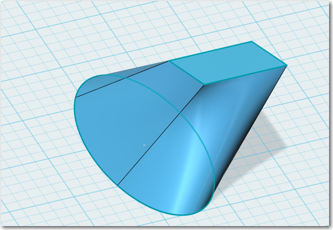
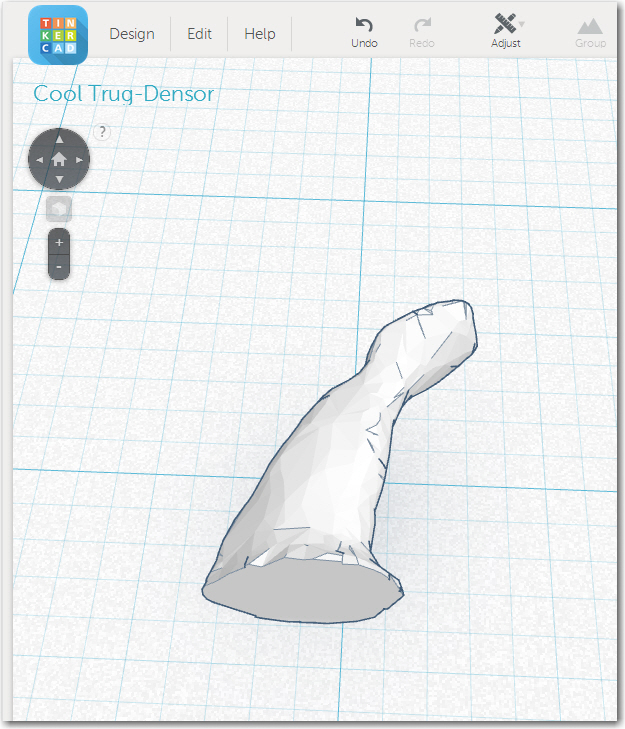
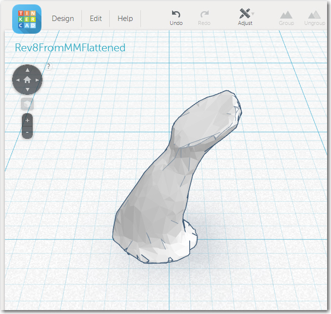
Option 2 – Separate the rotation feature from the attach/detach feature: The snap ring exercise convinced me that I needed to separate the rotation feature from the attach/detach feature. Conceptually, this meant that I had to partition the system into three parts rather than two; the flap grip, a ‘converter’ piece that would attach/detach from the flap grip on one side, and would form a rotational surface with the remote caddy piece on the other, and the caddy piece itself. Separating the design into three pieces vs two wasn’t really much of a conceptual leap anyway, as I had already done most of this in the previous incarnation when I used the 123D Design’s ‘Loft’ feature to transition from the flap grip ellipse to the caddy rectangle. All I had to do was to make that transition into it’s own separate piece, with some sort of attach/detach mechanism on the bottom, and a rotation feature on the top. Of course I still had to figure out what those mechanisms were, but details, details, details! ;-).
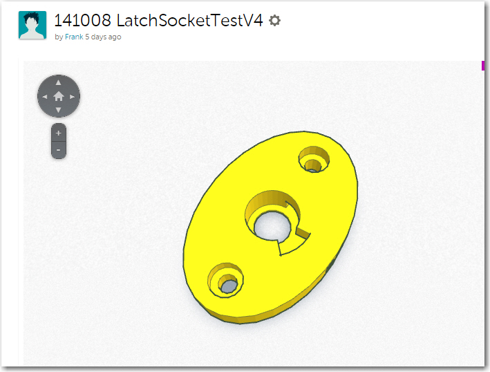
Quarter-Turn Latch For Attach-Detach: While I was doodling around trying to figure out a good mechanism for latching/unlatching the center ‘converter’ section to the flap grip, my wife happened to look over my shoulder and casually say “what about a quarter-turn fastener?”. My first thought was “nah – WAY too hard”, but the more I though about it, the more is seemed like that might not be such a crazy idea after all. One of the many cool things about 3D printing is its ability to form internal structures that aren’t possible via normal milling/machining techniques, another is its ability to convert a solid shape to a cavity and vice-versa, and another is the way it facilitates rapid experimentation. The combination of these three things allowed me to design complementary plug/socket designs, and then rapidly iterate through several versions to improve the design.
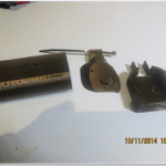
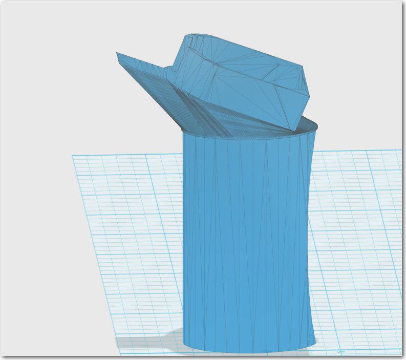
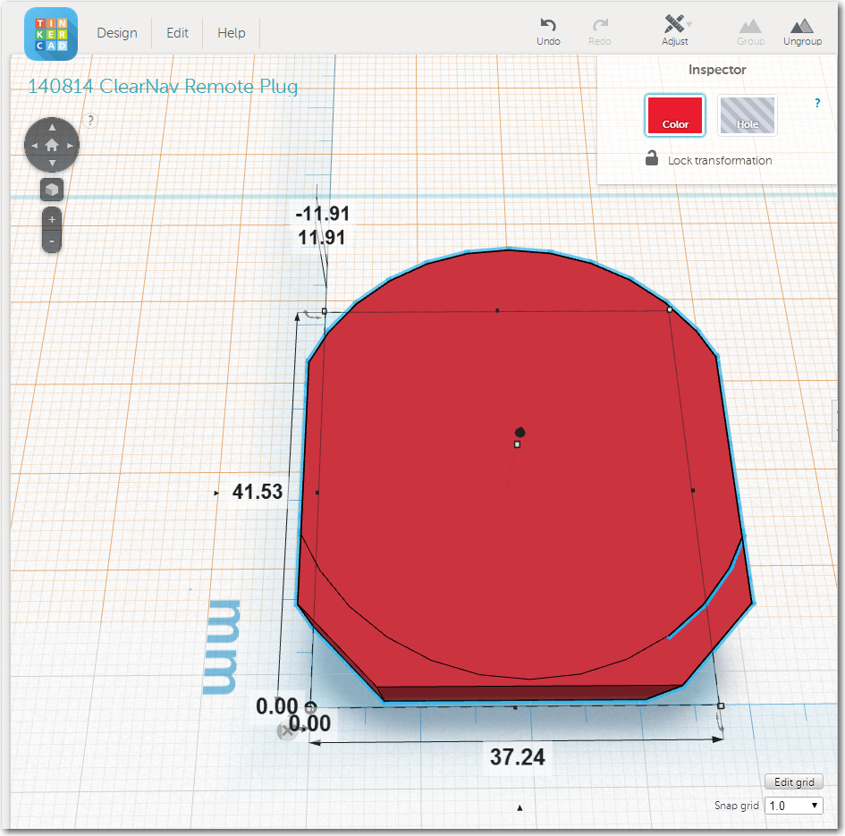
I started with a circular base for both the ‘plug’ and ‘socket’ version of the quarter-turn latching mechanism, but rapidly changed to an elliptical base that exactly matched the cross-section of the flap grip. I knew I would eventually need to transfer the mechanism to the top of the flap grip and the bottom of the identically-shaped bottom of the center transition section, so using the same shape for the experimental parts would make the transfer a LOT easier. The first set of trials were pretty clumsy, as I had no real idea what a good mechanism looked like, how to determine the amount of rotation from locked to unlocked, and which direction I wanted the locking rotation to go. Version 1 used a rectangular tongue for the latch, but I discovered this didn’t work very well, so this evolved to a pie-section tongue shape, and the complementary internal socket channel evolved to match.
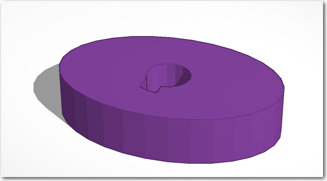
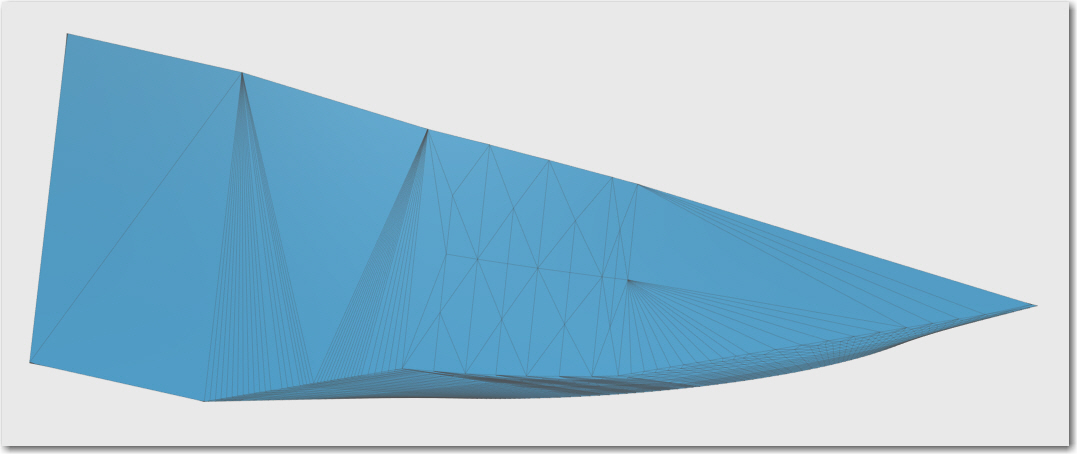
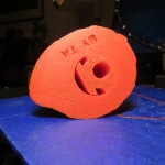
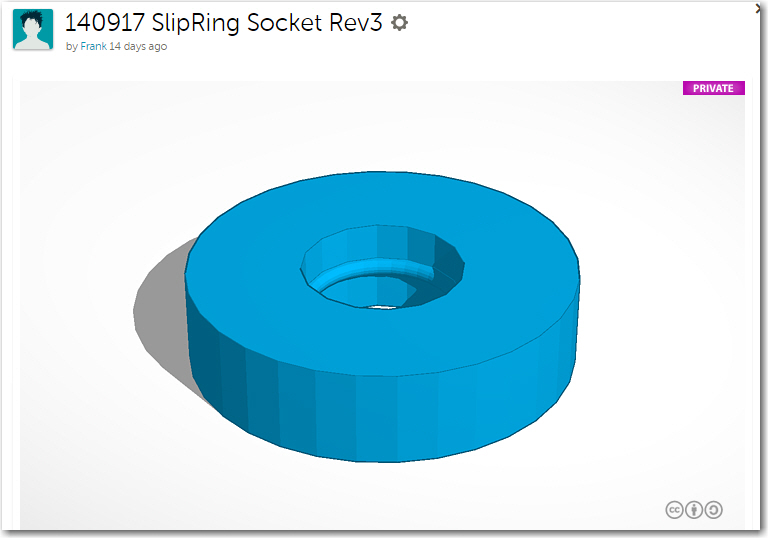
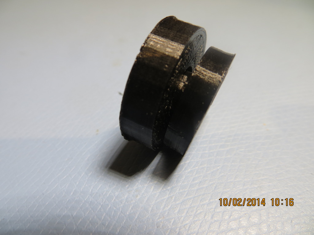
Version 1 of the quarter-turn fastener socket
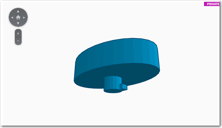
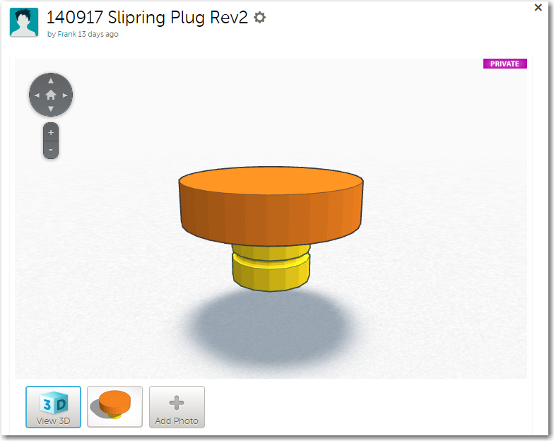
Version 1 of the quarter-turn fastener plug
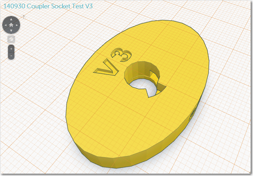
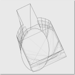
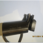
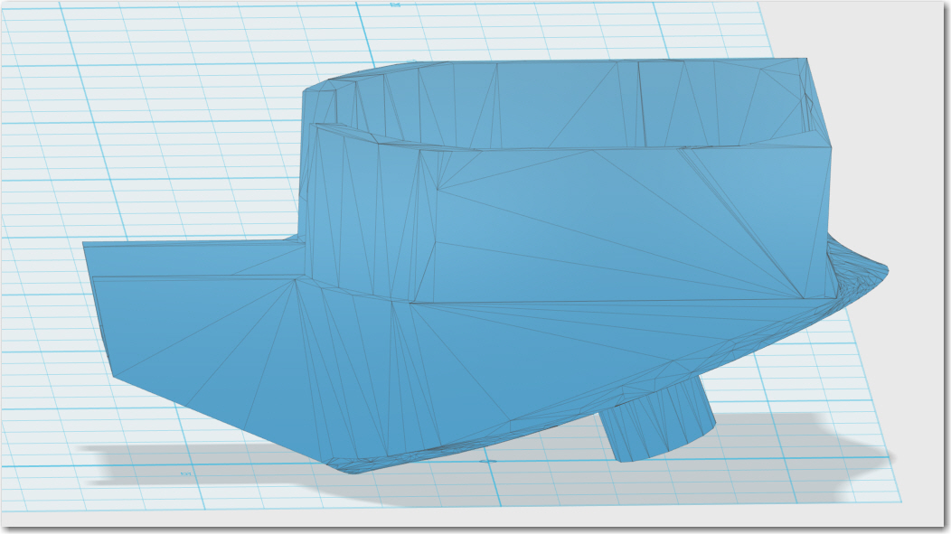
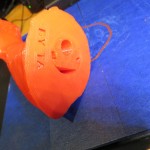
Version 3 of the quarter-turn latching mechanism
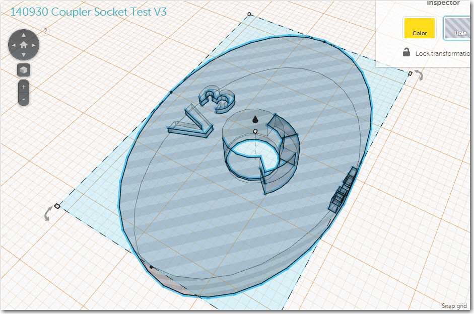
Version 3 of the quarter-turn latching mechanism with internal details shown
By version 3, I had also started adding ‘engraved’ version number and orientation reference marks to the experimental pieces as an aid for getting the lock/unlock orientations right (after having screwed this up a couple of times without the reference marks). I had also gotten smart enough (after some more screwups) to extract the design of the quarter-turn mechanism into its own file, so it could be added to whatever structure required it (and making it available for completely different future projects!).
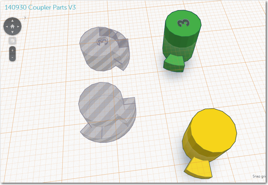
Version 2 and V3 plug/socket parts in their own design file
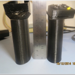
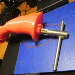
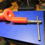
Doing this made it MUCH easier, for instance, to reverse the lock/unlock rotation direction when I discovered that the original orientation made the mechanism too easy to unlock inadvertently during normal use (50/50 chance and I blew it – again!). The finished (as much as anything gets finished in this project) product is shown below
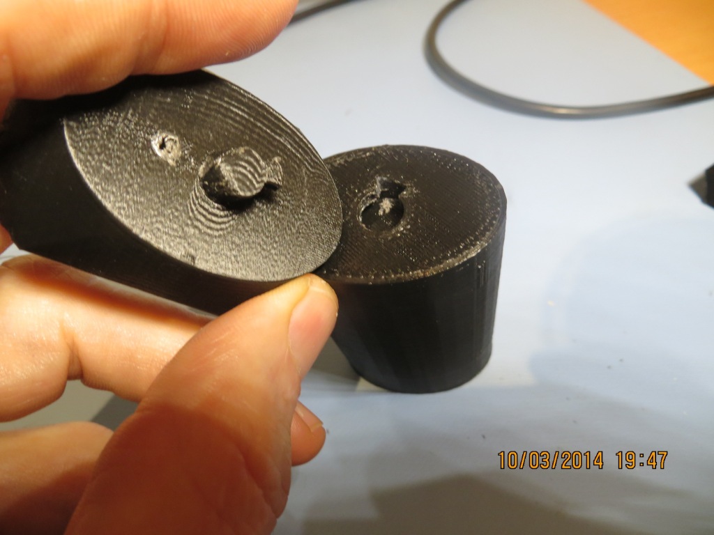
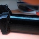
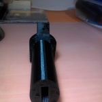
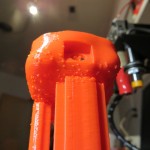
FlapGrip to center section quarter-turn locking mechanism.

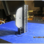
Center section in the locked position on the flap grip
Center section in the UNlocked position on the flap grip
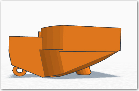
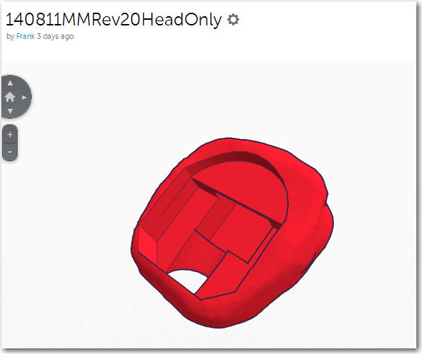
Rotational Feature: Based on earlier feedback from John, I wanted the remote caddy to be able to rotate with respect to the flap grip. In an earlier incantation, the piece that transitioned from the flap grip ellipse to the semi-rectangular remote caddy was integrated into the remote caddy, and the entire piece rotated about the top of the flap grip. This was OK, but the transition/caddy section could not be easily removed from the flap grip, making glider entry/exit potentially awkward. In the new setup the idea was to separate the transition section from the remote caddy so it could rotate around the top of the transition section, while the combined caddy/transition sections would attach/detach from the flap grip via the quarter-turn fastener. So, I needed a rotation mechanism, preferably with some sort of detent arrangement so John could try different rotation angles in flight. The detent requirement led to another series of experiments with snap-ring buttons, with a small protruding tip one button that engaged a set of radially distributed grooves on the other. The result, unfortunately, was that if the tip was sufficiently large to properly engage the grooves, it was also large enough to make it nearly impossible to ‘click’ from one groove to another. In other words, it turned out to be pretty much an ‘all or nothing’ kind of thing. Fortunately I still had a couple of the McMaster-Carr ball-spring plungers left over from the last go-around, and I replacing the protruding tip with a spring-loaded ball did the trick very nicely!
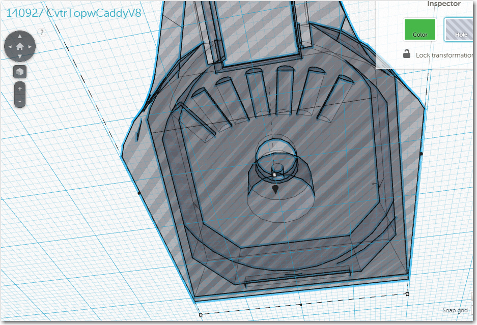
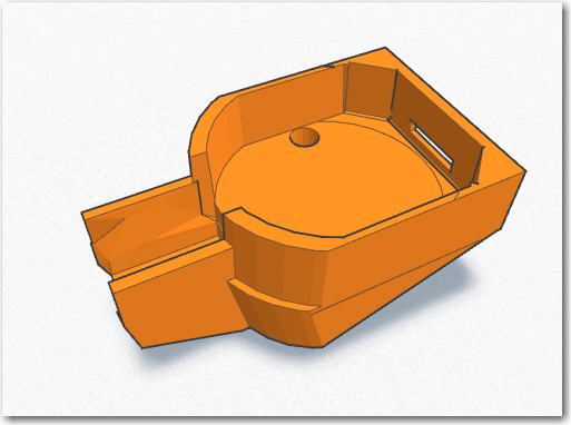
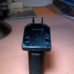
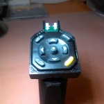
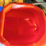
Remote caddy interior details showing rotation and detent arrangement
Remote caddy bottom surface showing detents. Note the ball-spring plunger in the top of the transition piece
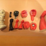
OK, so now we had the desired quick-release feature so John can easily remove the remote caddy (with its attached cable to the ClearNav) from the flap grip for glider entry/exit, AND the desired ability to rotate the caddy with respect to the flap grip axis! All it took was a little persistence, a genius wife, and about a million design/implement/test cycles ;-). The following photos show the various experimental parts generated, and the ‘final product’ (but of course, ‘final product is what I said the last time!)
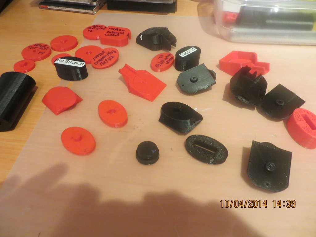
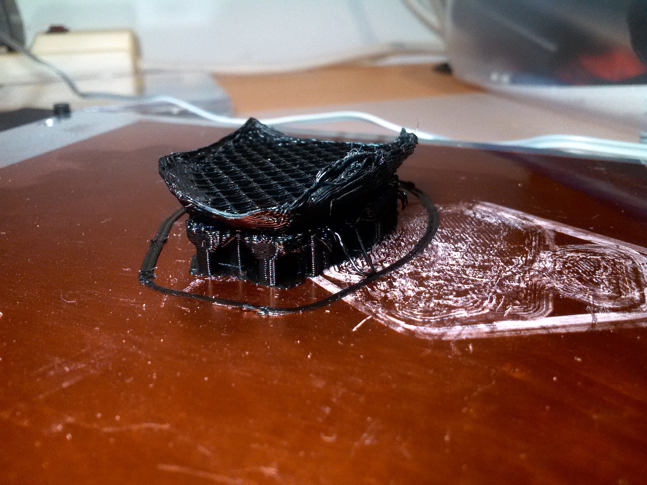
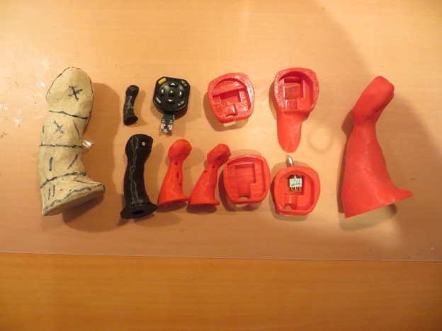
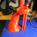
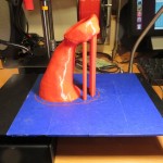
Collection of experimental printed parts

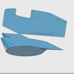
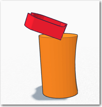
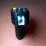
Disassembled system showing all three pieces

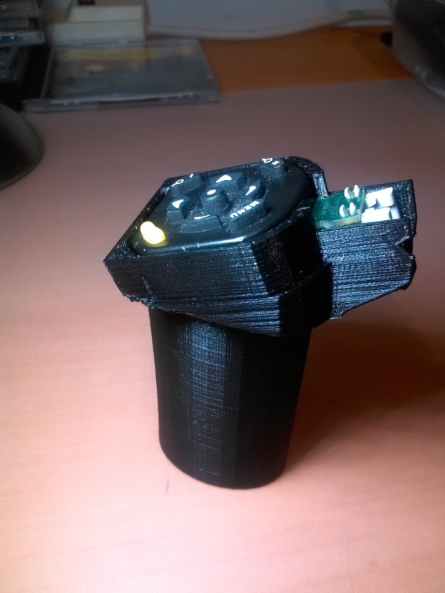
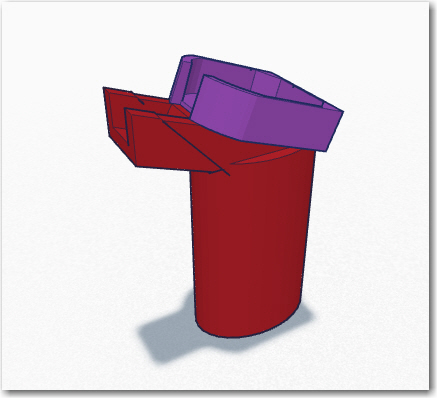
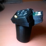
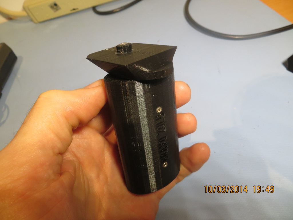
Assembled 3-piece system
Stay Tuned!
Frank