Posted 15 October 2017
Well, we have just about reached the end of the road with respect to the ‘IR Homing Module Integration’ adventure. As you may recall, at the very start of this trip (a couple of centuries ago back in August of this year) I showed the following block diagram of the proposed integration architecture
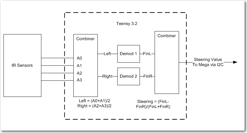
Teensy 3.2-based IR Demod module block diagram
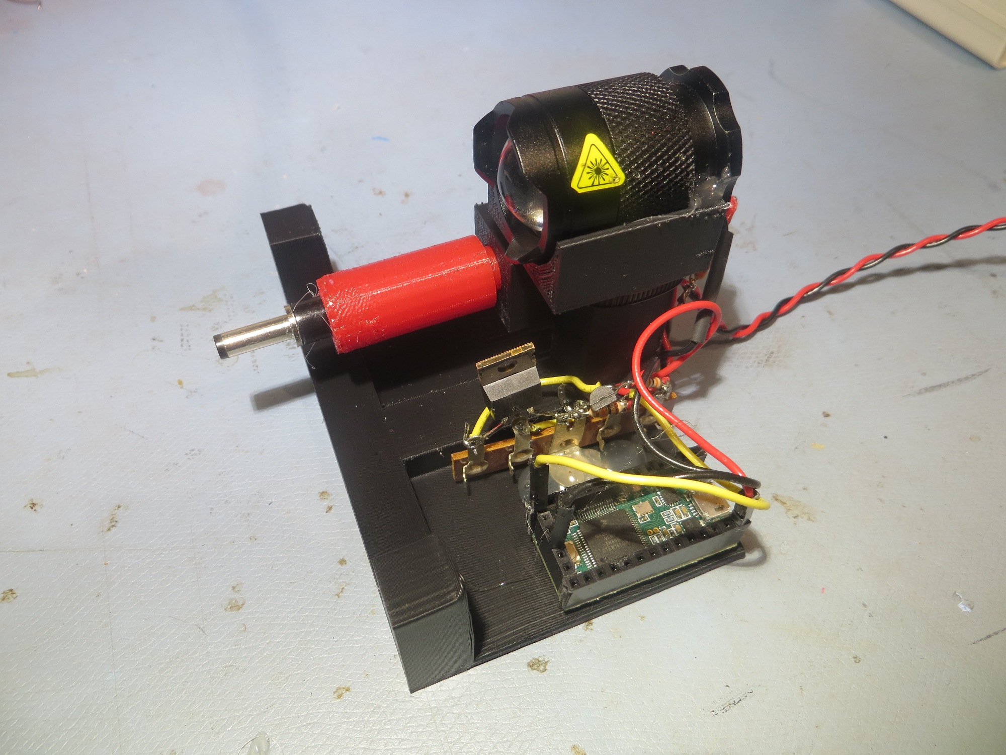
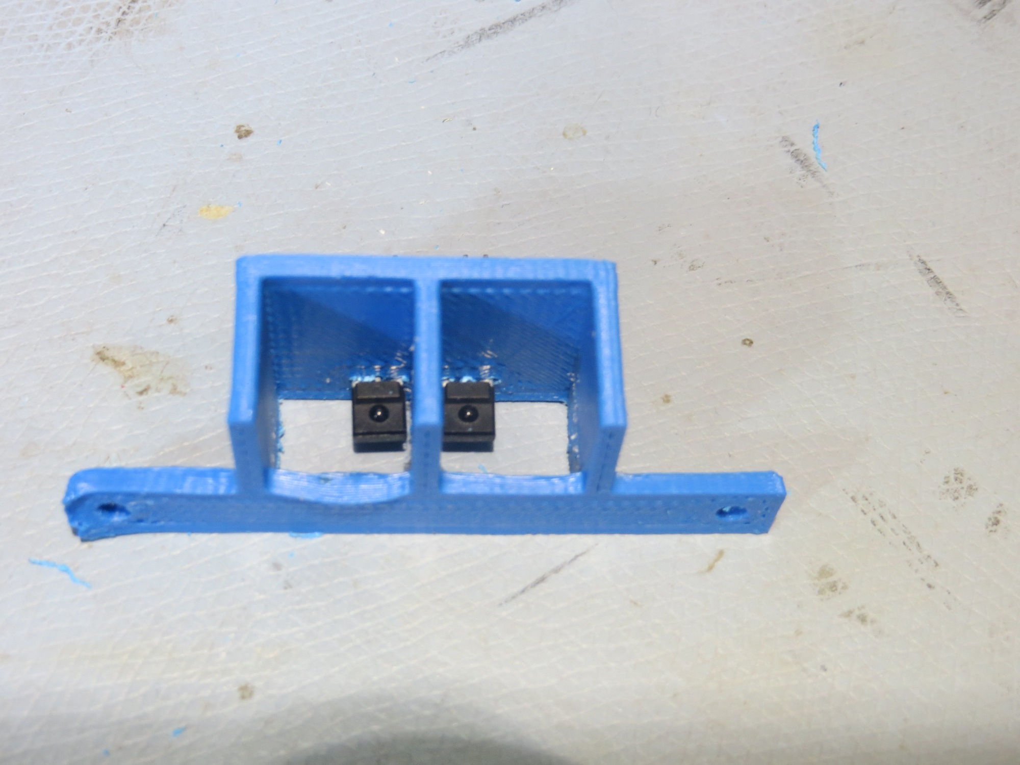
The above architecture actually worked almost exactly as planned, except for using only two phototransistors vs the four in the original design, as shown below
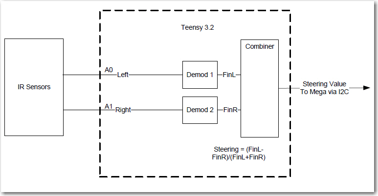
Revised IR Demodulator block diagram. Note the removal of two phototransistors and the input combiner
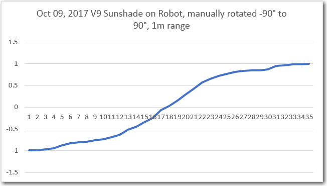
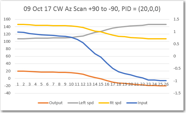
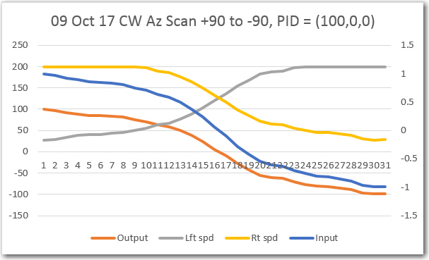
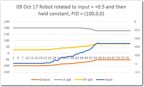
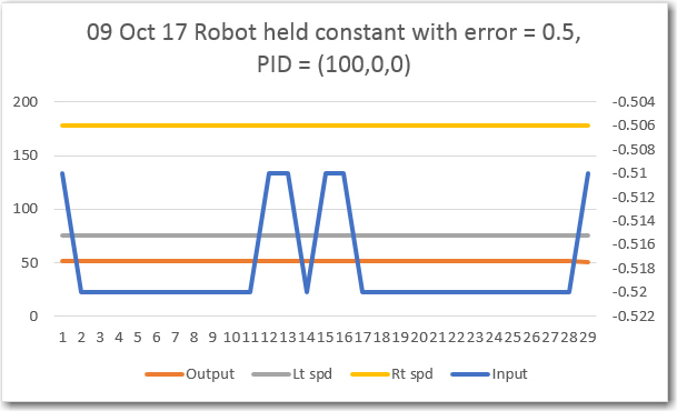
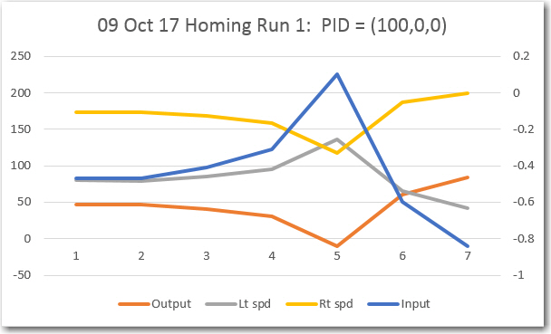
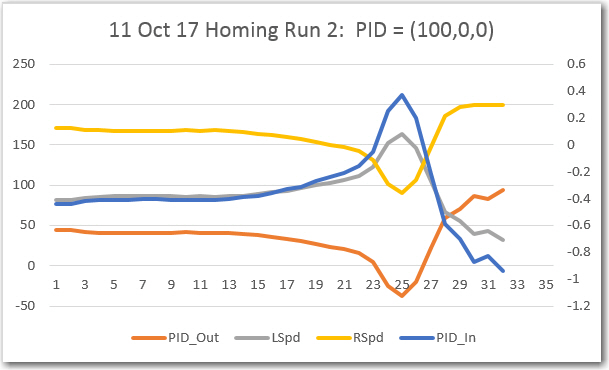
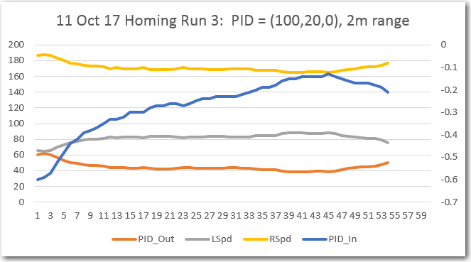
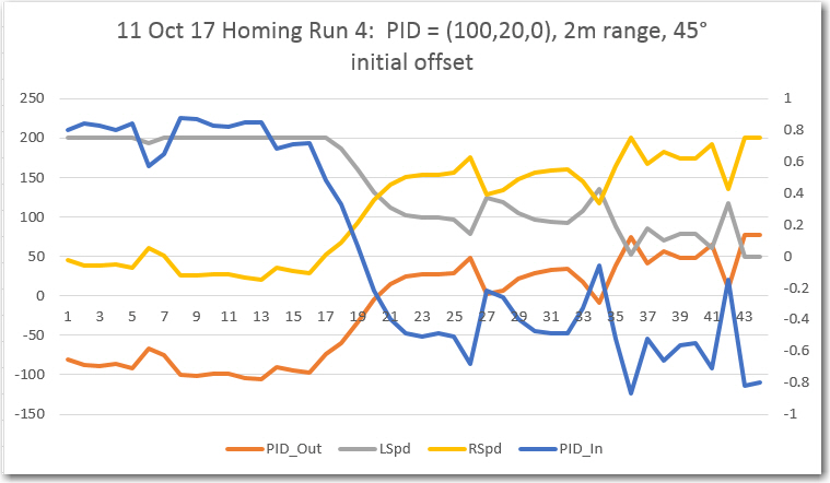
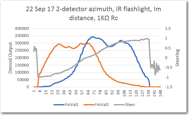
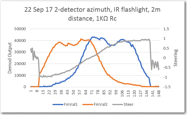
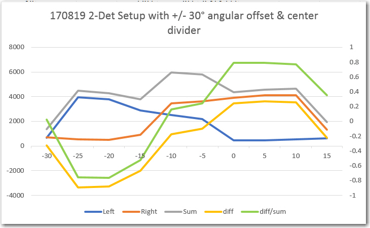
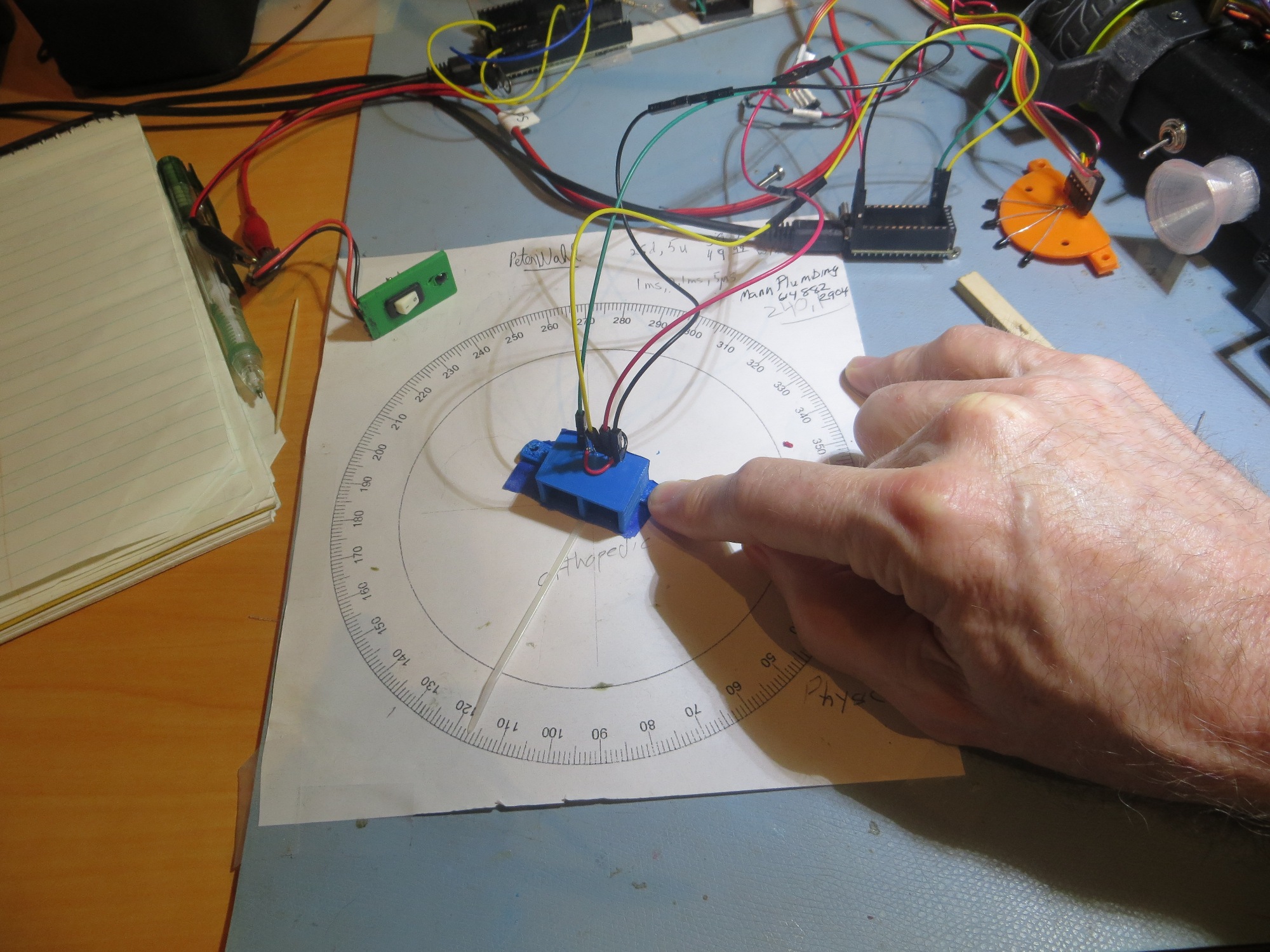
After literally dozens of trials on my 1m (aka workbench) and 2m ranges (aka the floor of my lab), I believe I have arrived at a reasonably successful set of PID parameters for Wall-E2 to use when homing to a charging station. As usual, after going all around the barn with different P, I, & D values, I wound up with the simplest possible set of parameters, namely PID = (200,0,0). The ‘200’ value is due to the use of a (L-R)/(L+R) computation in the IR homing module, resulting in a steering value output that ranges from -1 to +1.
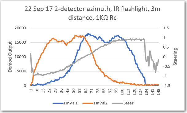
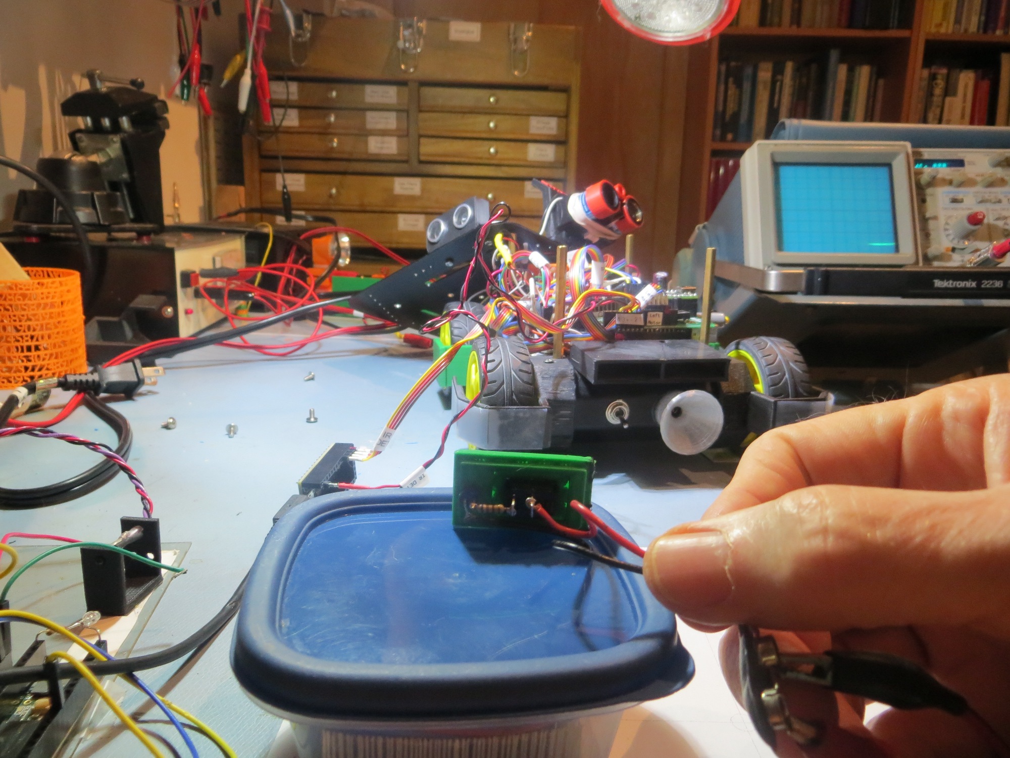
While the result at the moment is far from perfect, it is pretty good. Wall-E2 can now successfully home to and mate with the charging station from at least 3m away, with wall offset distances from 50-91 cm as shown in the following videos (as can be seen in the last video, there is still some work to be done for wall offsets in the 25cm range)
So, the IR Homing Module Integration project is basically complete. To recap, the idea for an interference-resistant IR homing scheme using a square-wave modulated IR beacon and a companion ‘degenerate N-path Band-pass Filter’ demodulator started back in May of this year during a visit from my old friend and mentor John Jenkins (see this post). Since then, Wall-E2 and I have done the following:
- Researched the basic theory behind the ‘N-path band-pass filter’ technology
- Designed and implemented (with John’s help) a two-channel version of the technique using an arduino Uno.
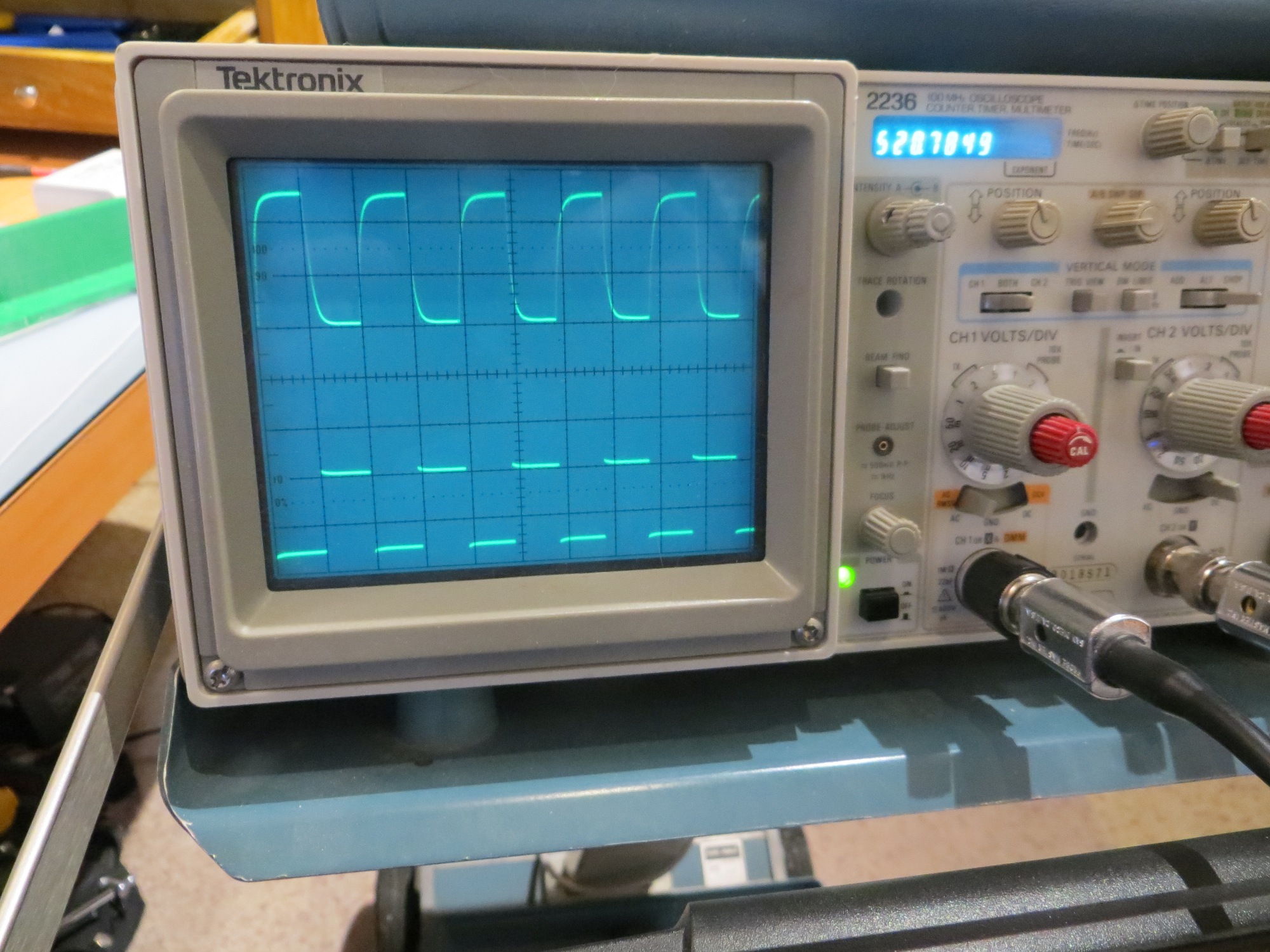
- When the Uno turned out to be too slow for operation at the desired 520Hz square-wave frequency, reduced the operating frequency by a factor of 10 to 52Hz to verify proper operation
- Researched faster alternatives to the Uno, and eventually settled on the Teensy 3.x line of micro-controllers. This hardware change allowed me to run the algorithm successfully at 520Hz, while simultaneously cutting the required real-estate by a factor of four, and the current drain by a factor of two – neat!
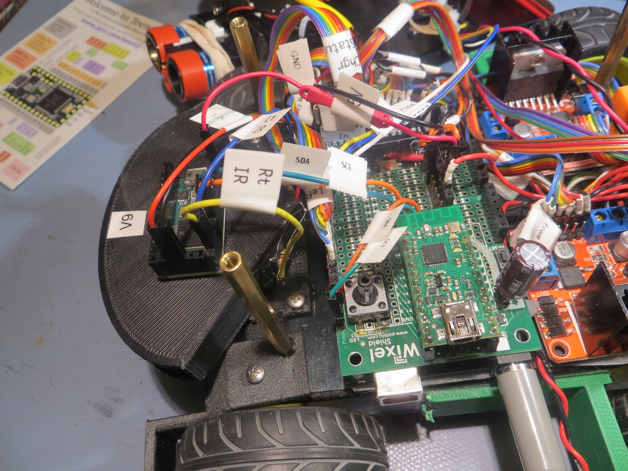
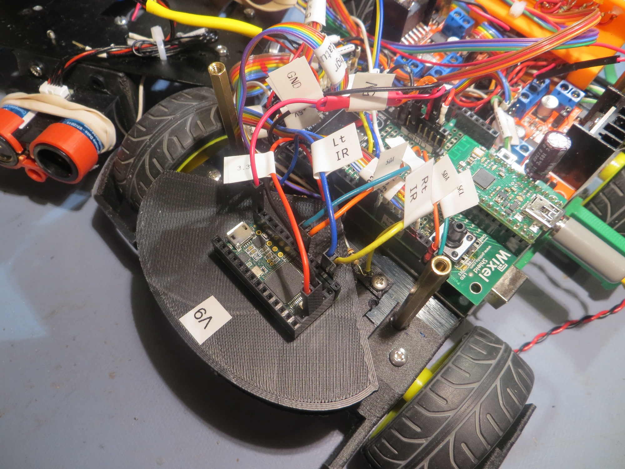
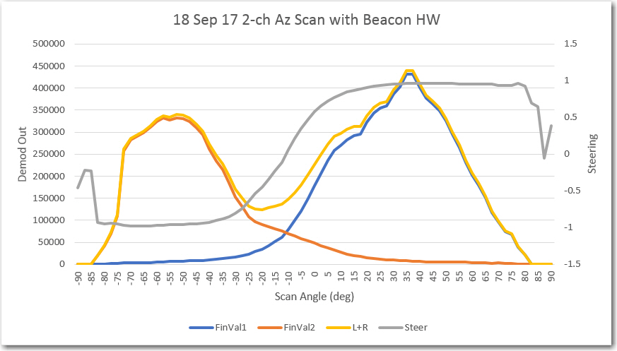
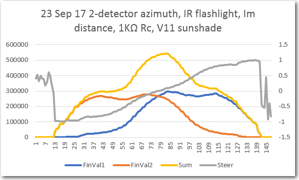
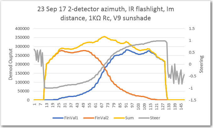
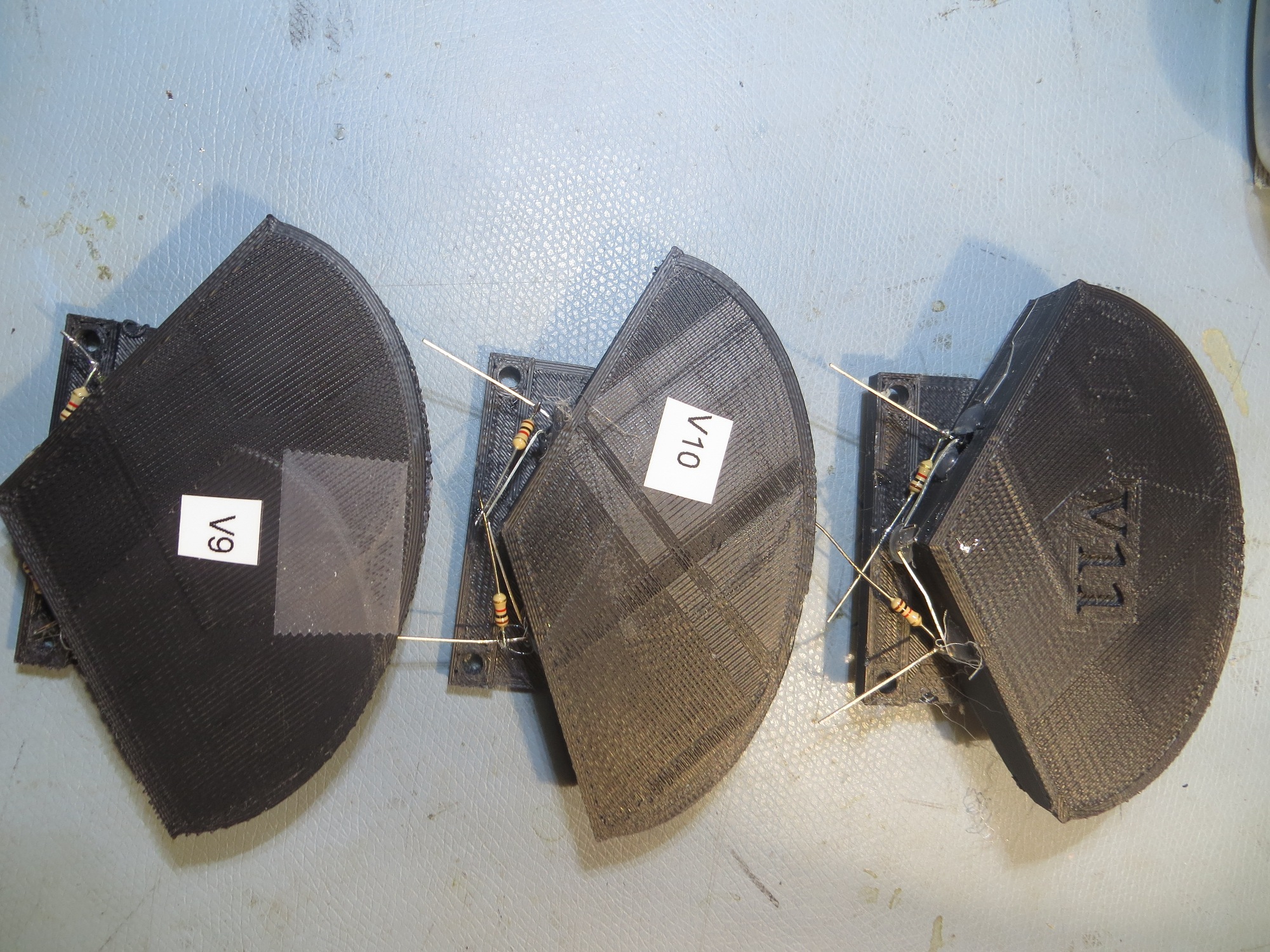
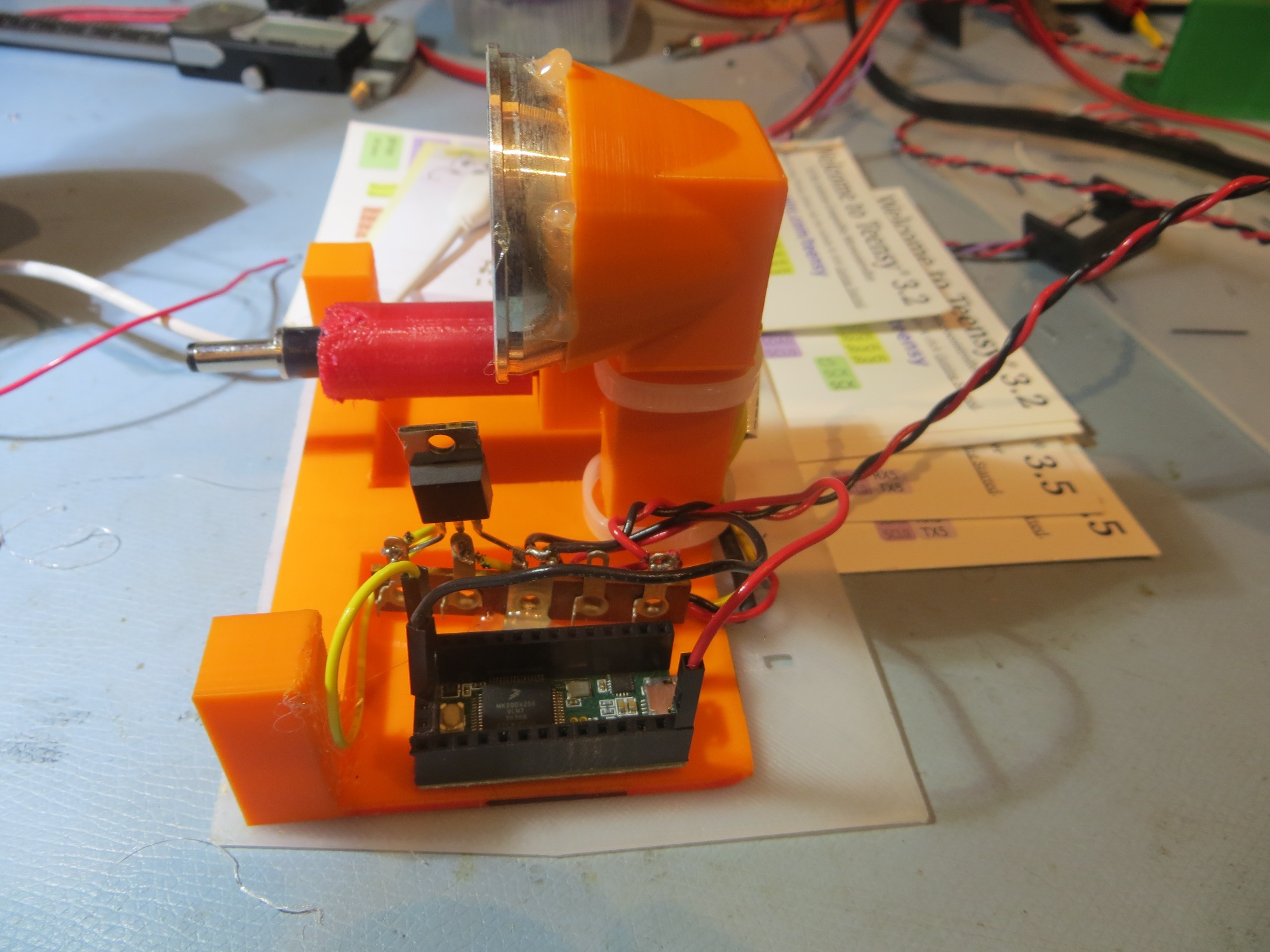
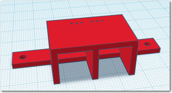
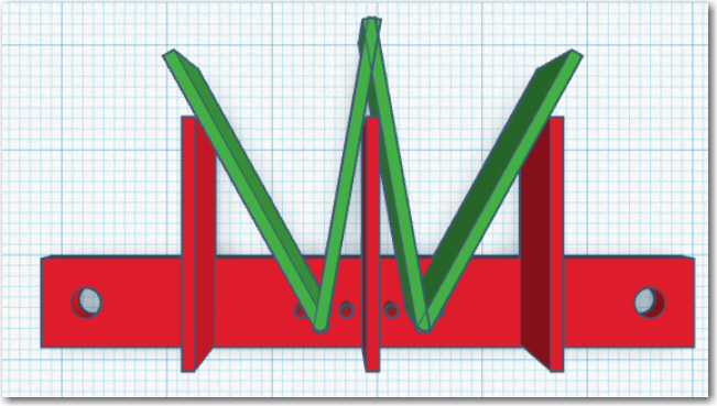
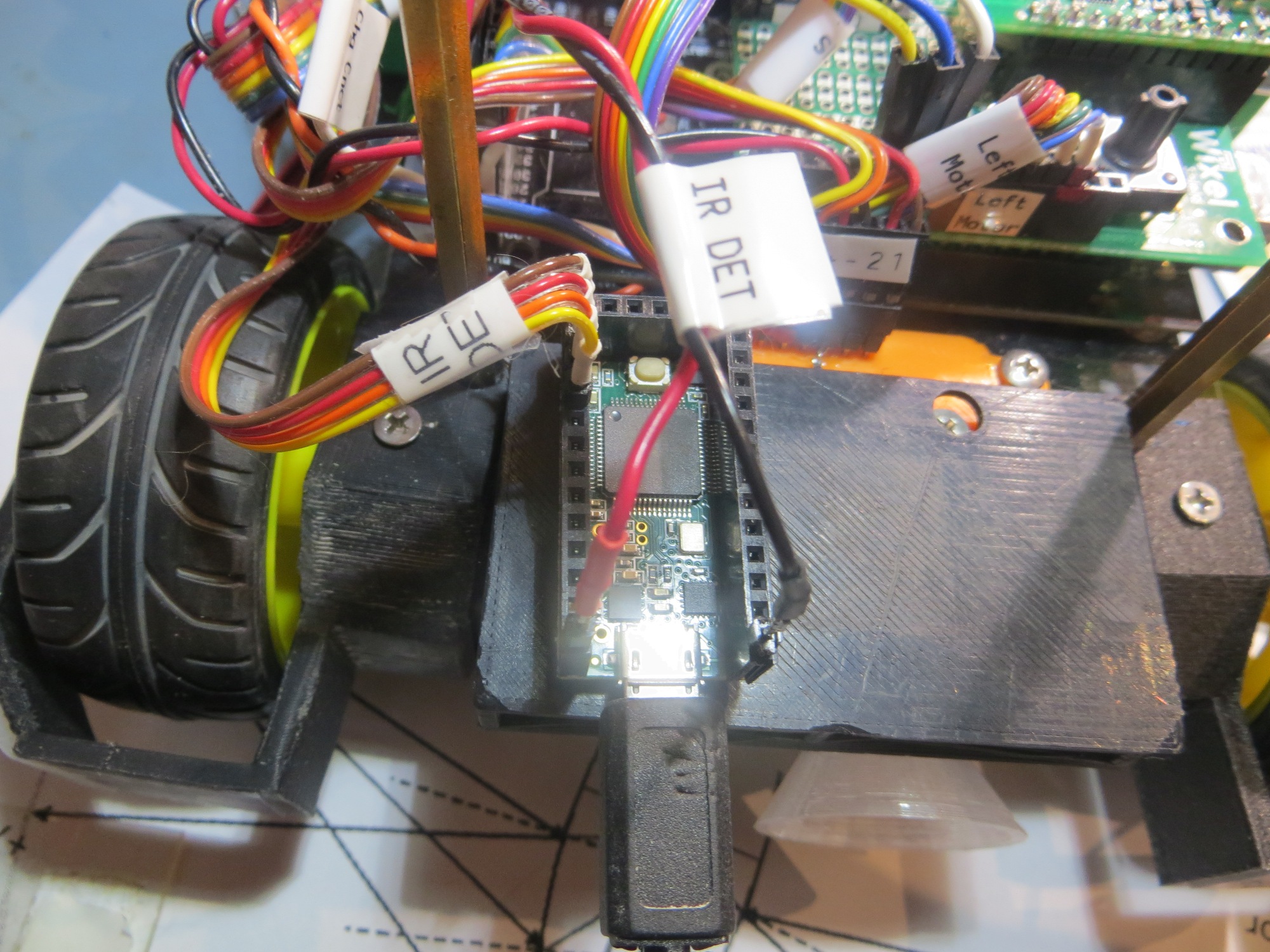
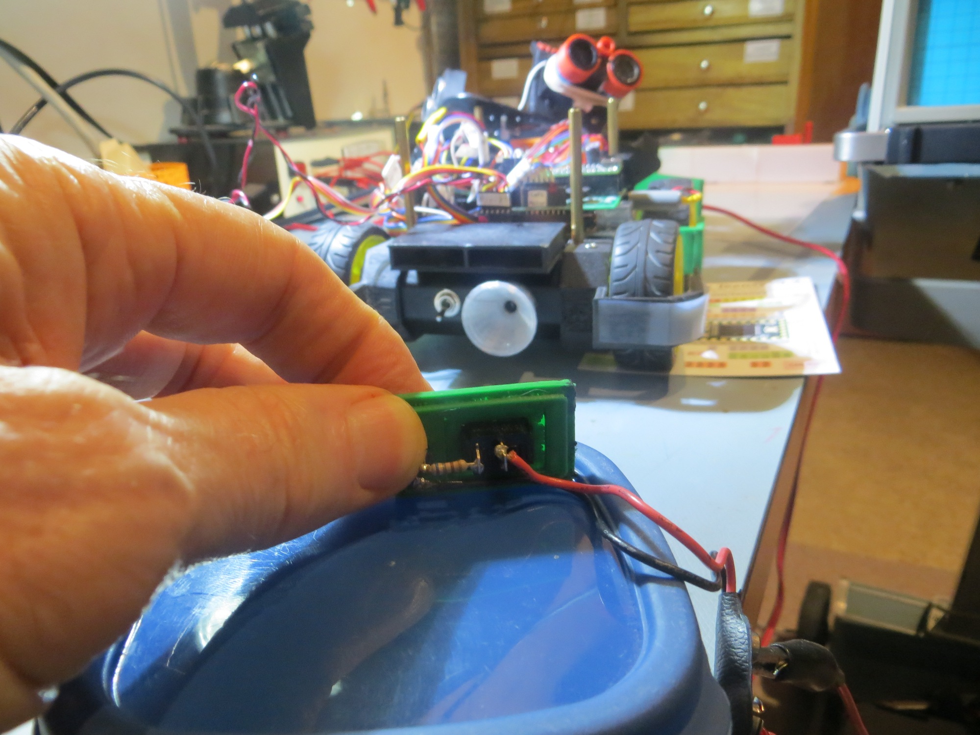
- Designed and implemented the ‘crushed funnel’ two-phototransistor detector sunshade.
- Integrated everything onto the Wall-E2 robot.
- Demonstrated successful homing in the presence of overhead halogen lighting
Remaining Work:
There are still some things that need to be cleaned up to complete the integration, but it is mostly minor stuff:
- I’m still not entirely happy with the inability to successfully home & mate with the charger for wall-following offsets below about 25cm, but I don’t think there is anything I can do realistically to solve that problem; what I can do, however, is to make sure Wall-E2 starts homing far enough away from the nearest wall to avoid that problem. This will probably mean something like a pre-homing maneuver if the nearest wall distance is too small (or maybe even changing the basic wall-following algorithm to maintain a minimum distance of > 25cm)
- Along the lines of belt-and-suspender designs, I probably also need to implement some sort of fallback algorithm if, despite all my best efforts, Wall-E2 still manages to impale itself on one of the lead-in rails. When Wall-E2 is in normal wall-following mode and gets stuck, it has a way of detecting that condition and recovering, but that scheme isn’t currently active during homing operations. I just need to copy that capability into the homing mode, and hopefully Wall-E2 will cooperate.
- There’s a whole bunch of commented-out stuff and debugging printout code scattered through the program right now, and that stuff needs to be cleaned out before I forget (if I haven’t already) what it was originally intended to do.
In any case, it is time to declare victory move on to the next challenge, as soon as I figure out what that might be.
Stay tuned!
Frank