Posted 2 April 2017
No, this is not an April Fools prank – but an actual geek-type 3D printer project using 3DXTECH’s carbon fiber impregnated PETG filament.
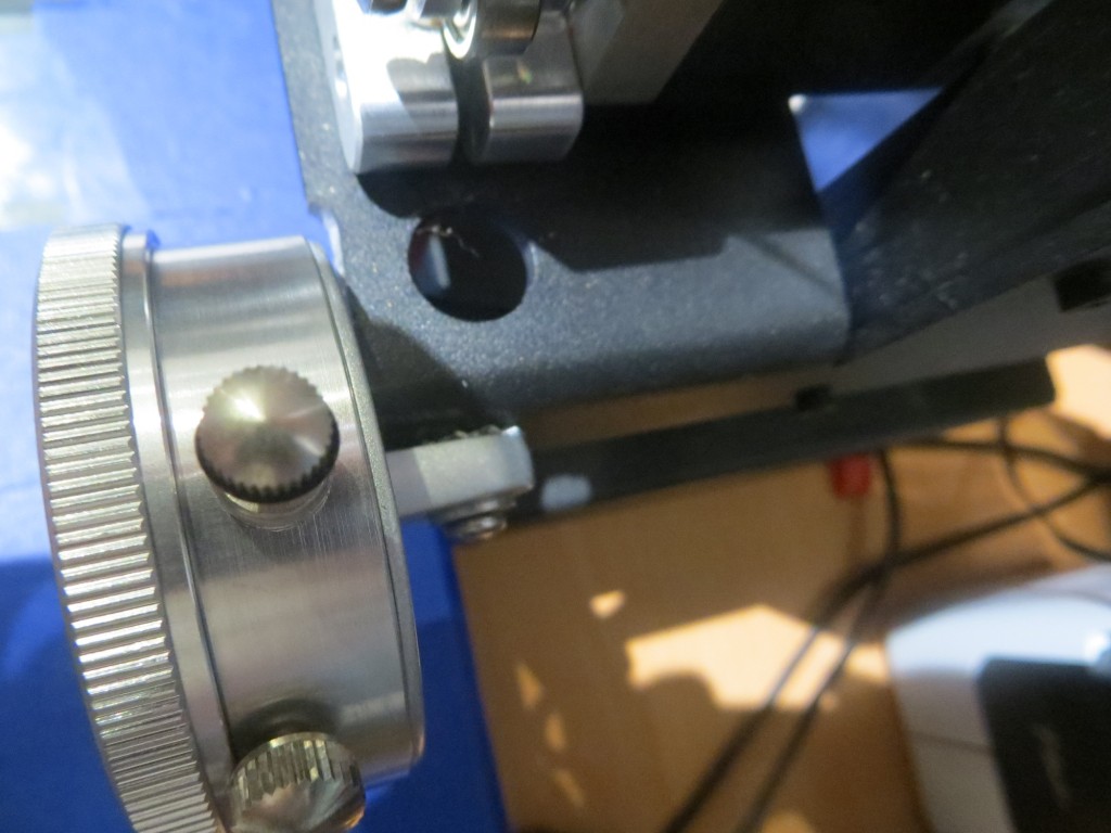
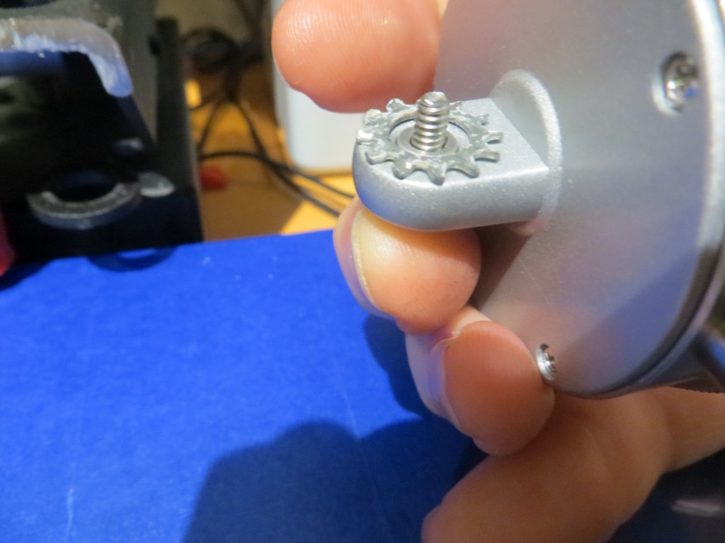
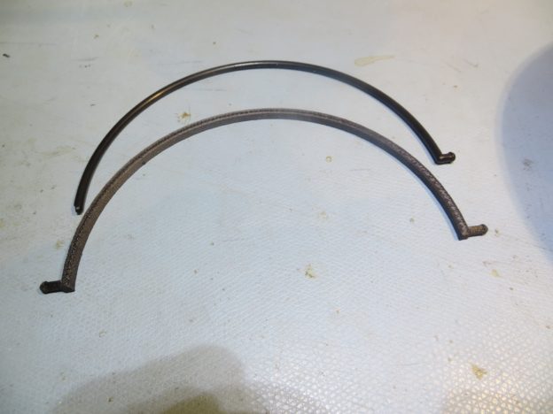
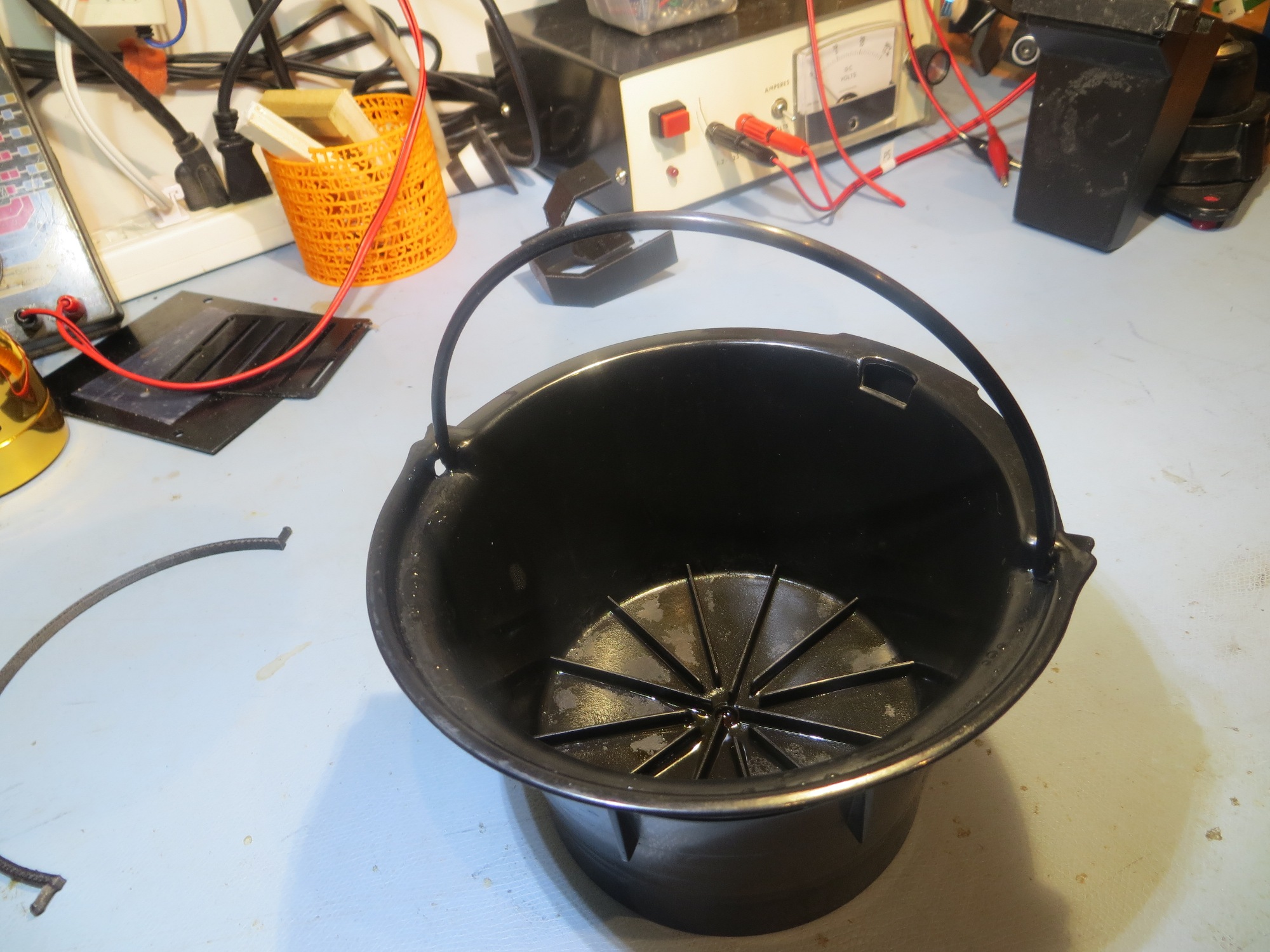
A day or so ago I was preparing my morning coffee as usual, when I discovered the little plastic ‘milk pail handle’ handle on the coffee filter holder had somehow gotten broken, as shown in the following photos
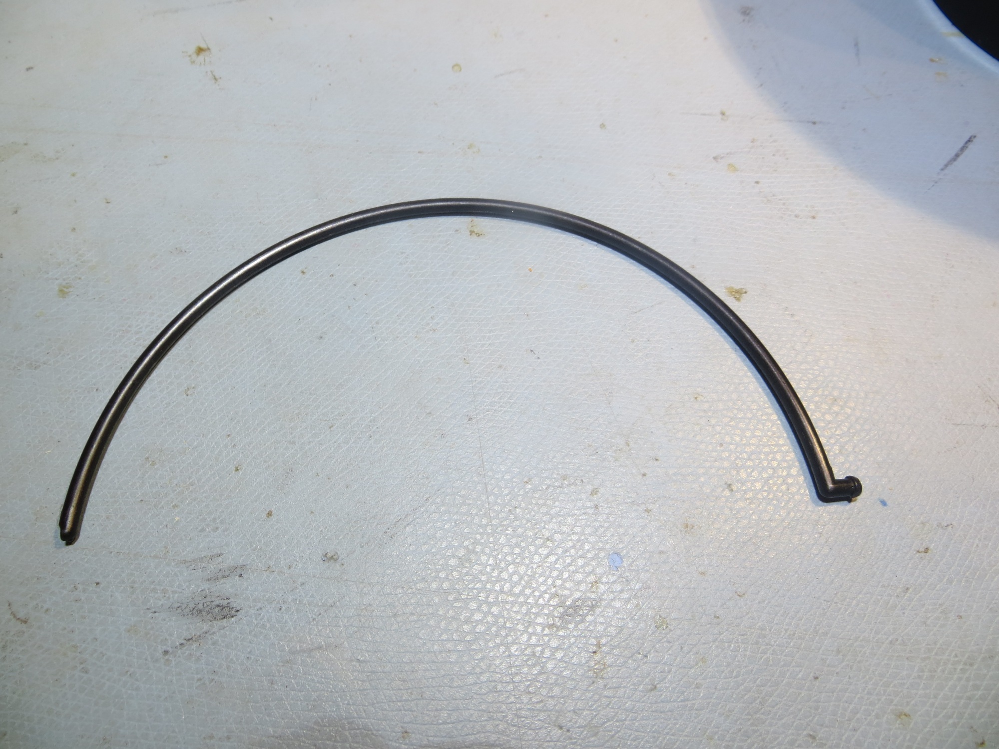
broken handle – note the missing tip on the left side
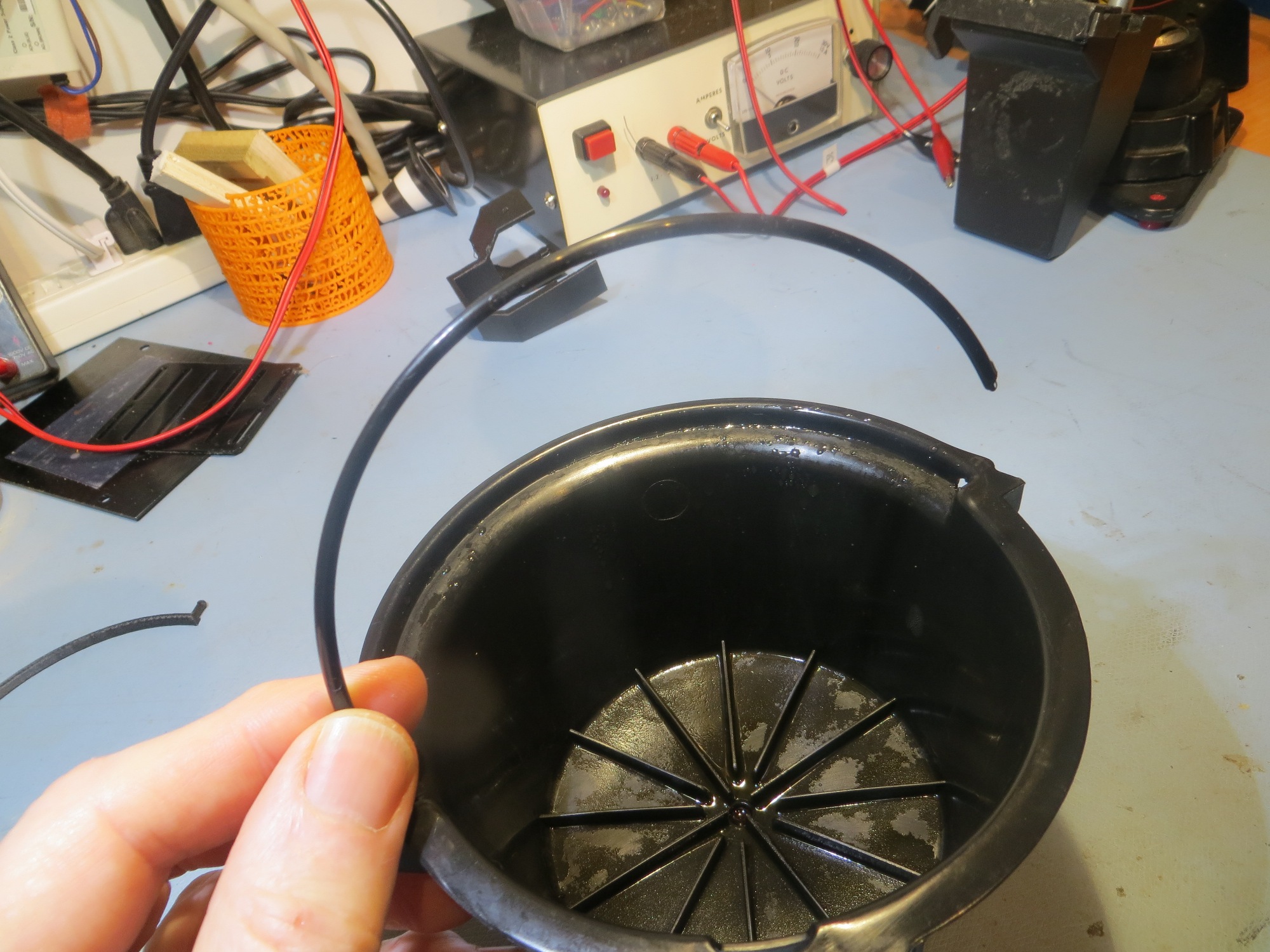
broken handle in action (or in this case, INaction)
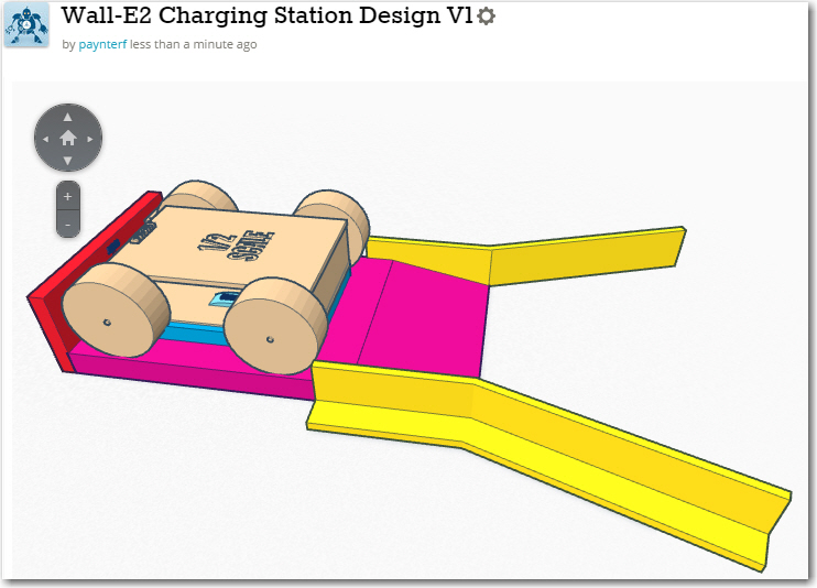
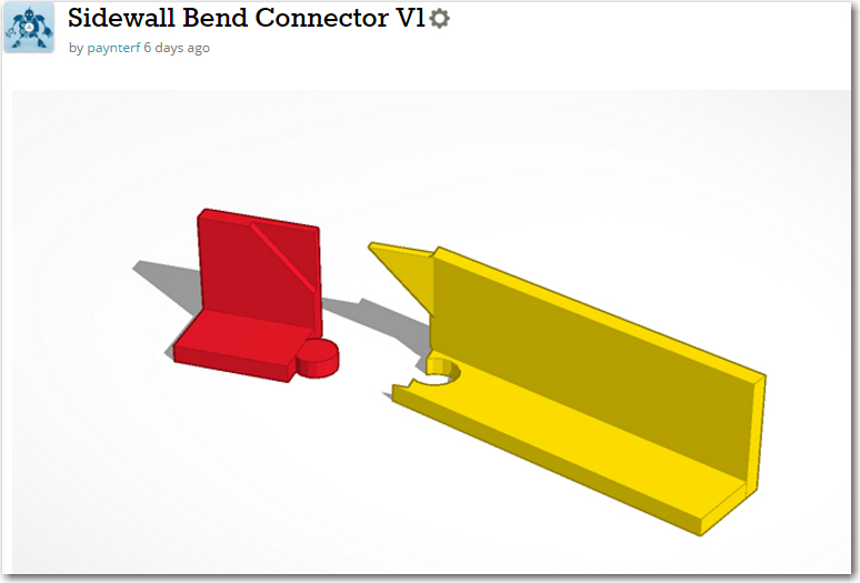
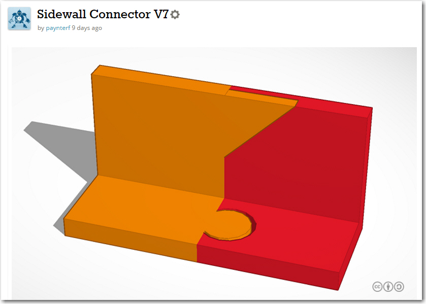
So, since I hate defective products like this, and since I happened to have a 3D printer and some CF-PETG handy, I decided to see if I could 3D print a replacement. Designing the replacement in TinkerCad turned out to be pretty straightforward, using a rectangular cross-section for the handle rather than the original circular design. The two retainer tips are cylinder sections (actually they are the ends of the same cylinder – with the middle removed along with the center of the disk making up the handle. The TinkerCad design is shown in the following screenshots
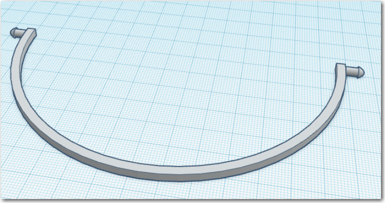
Finished design
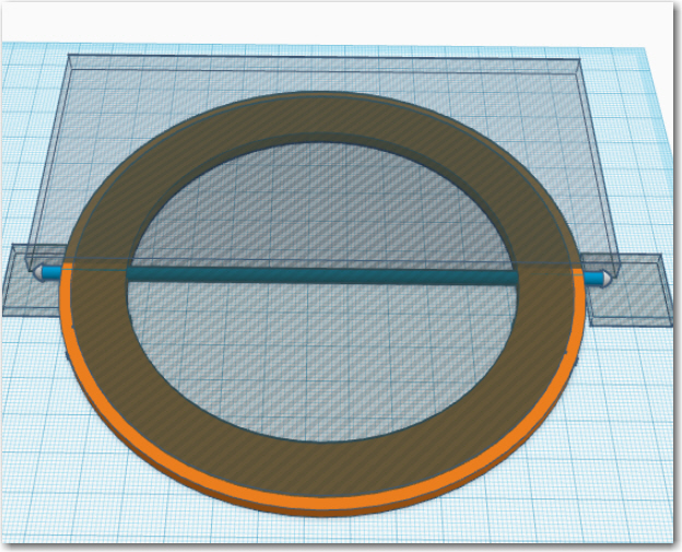
exploded view
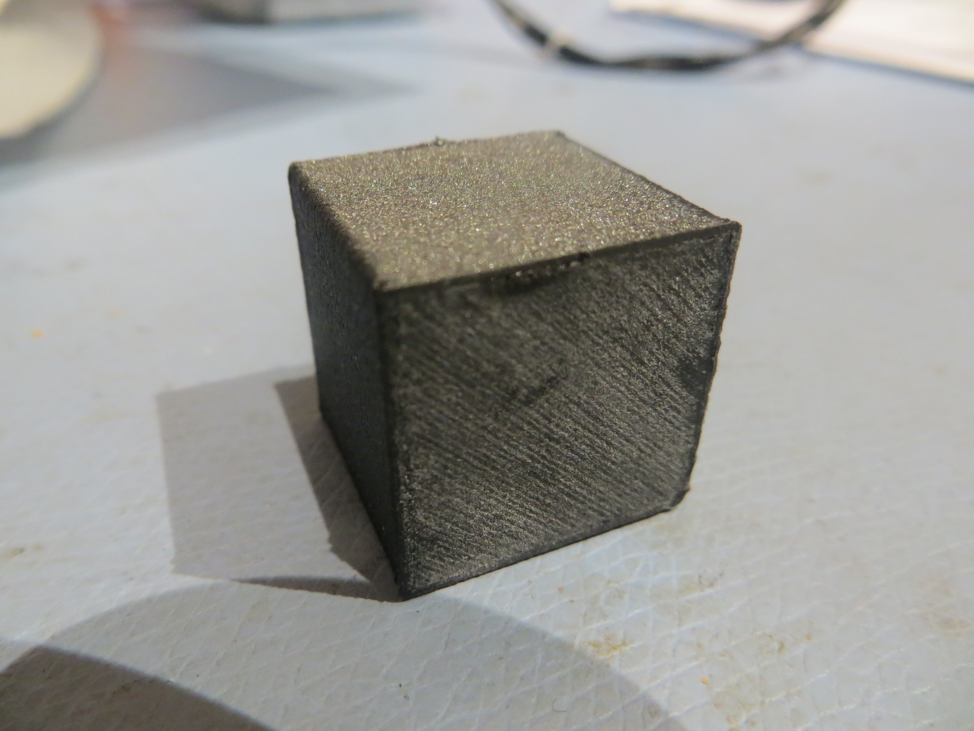
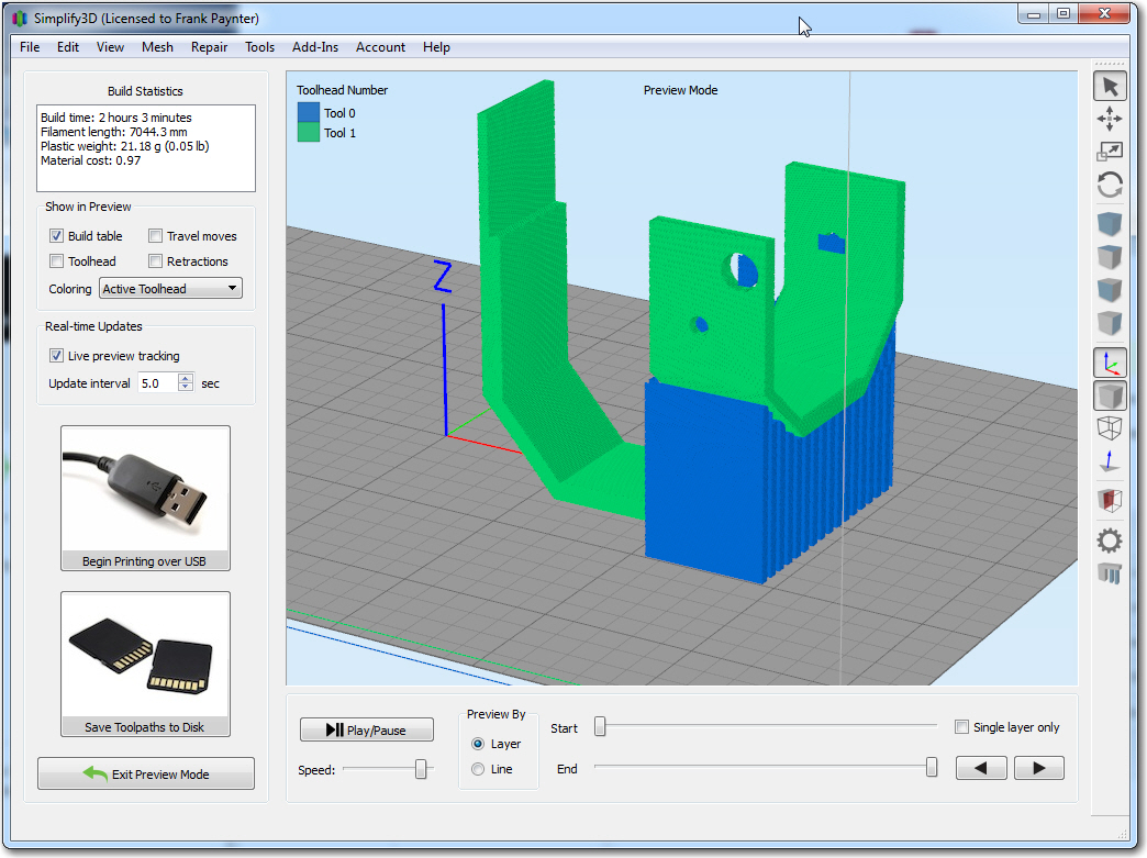
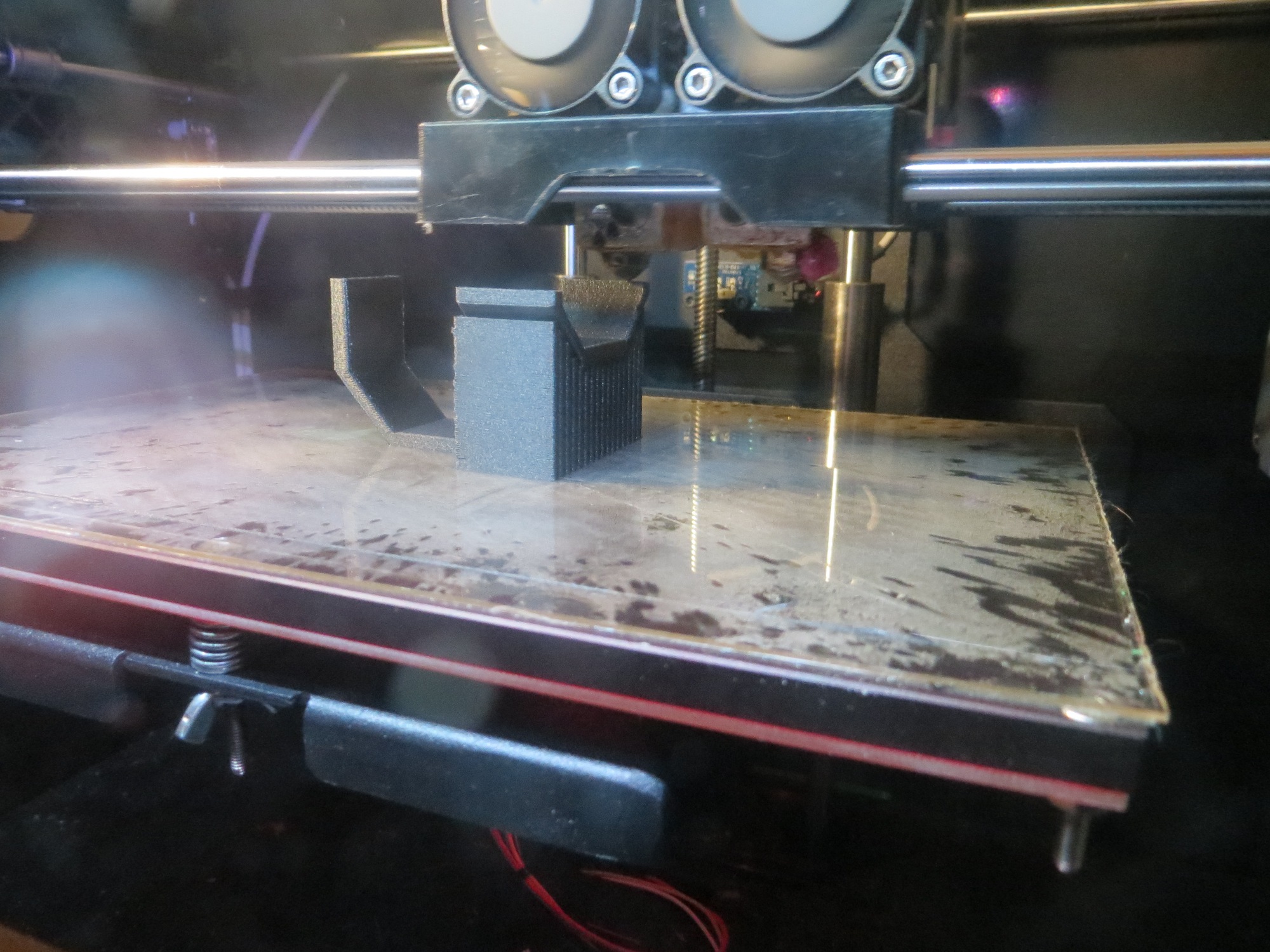
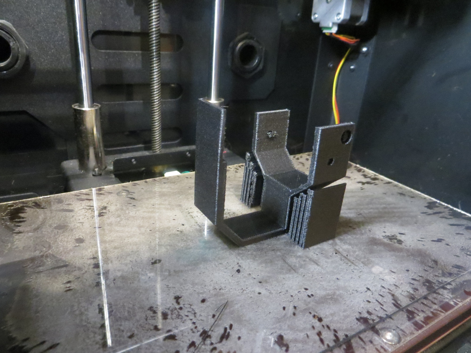
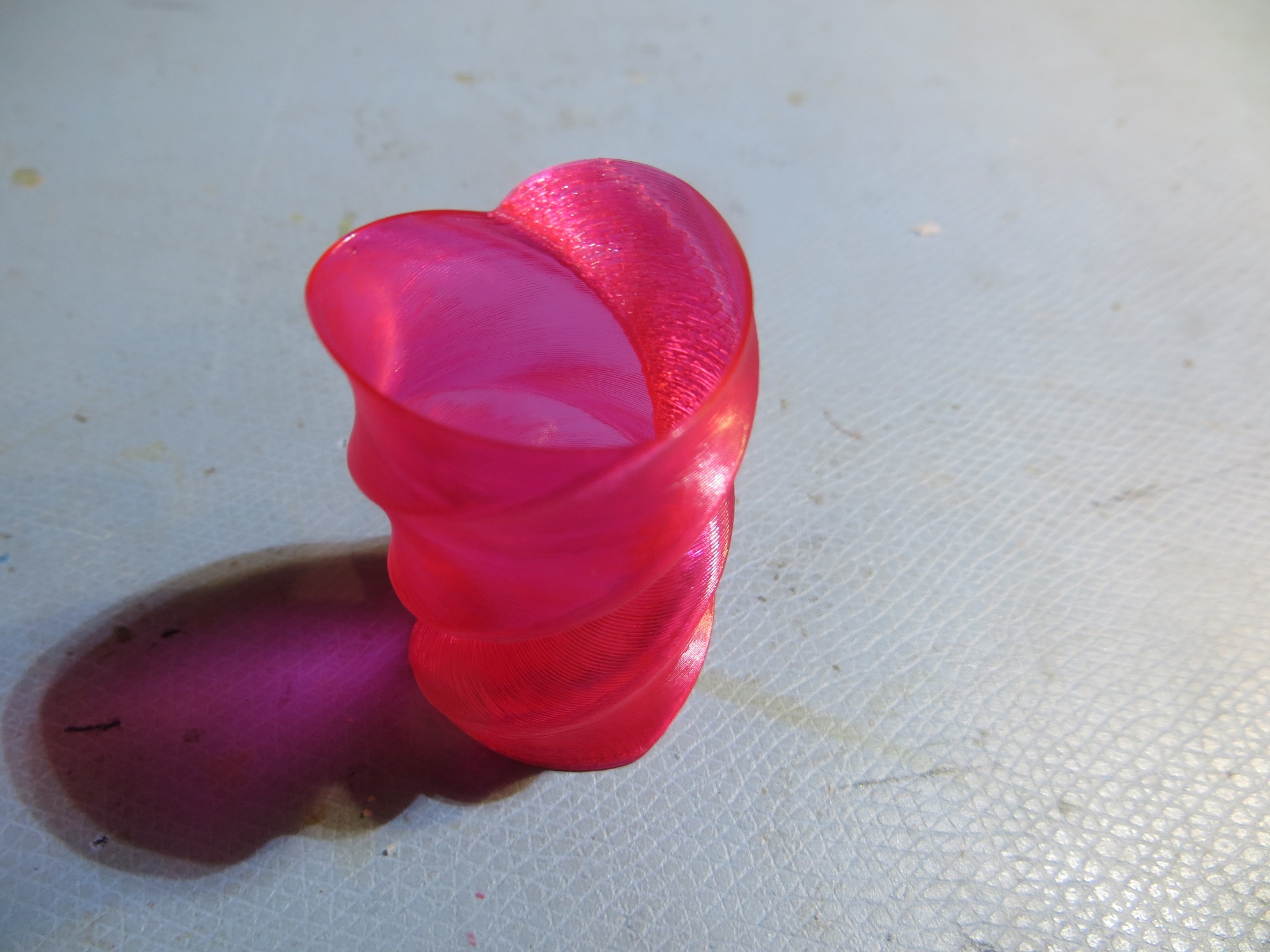
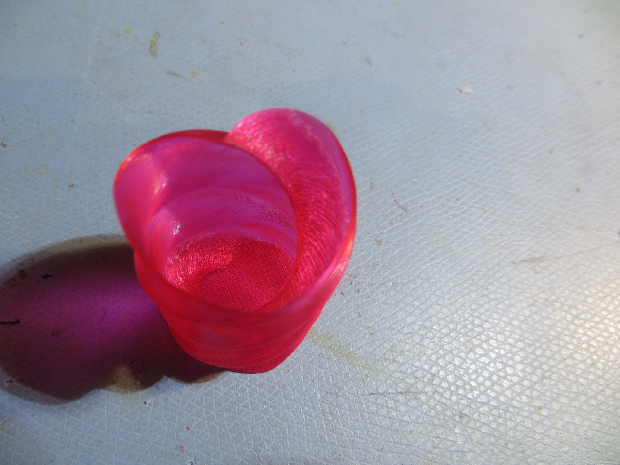
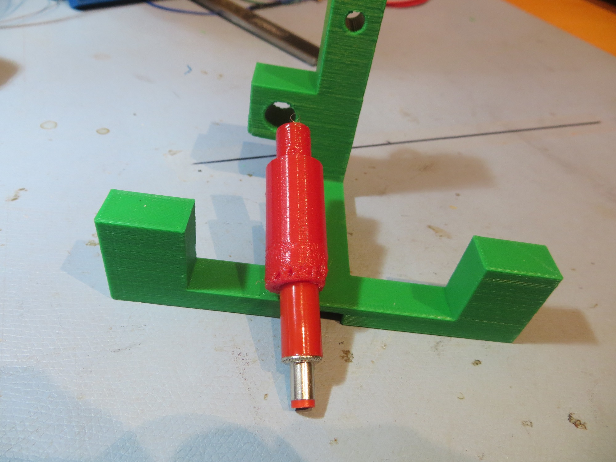
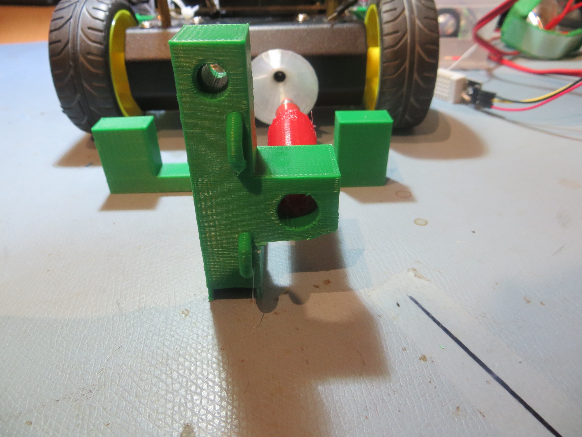
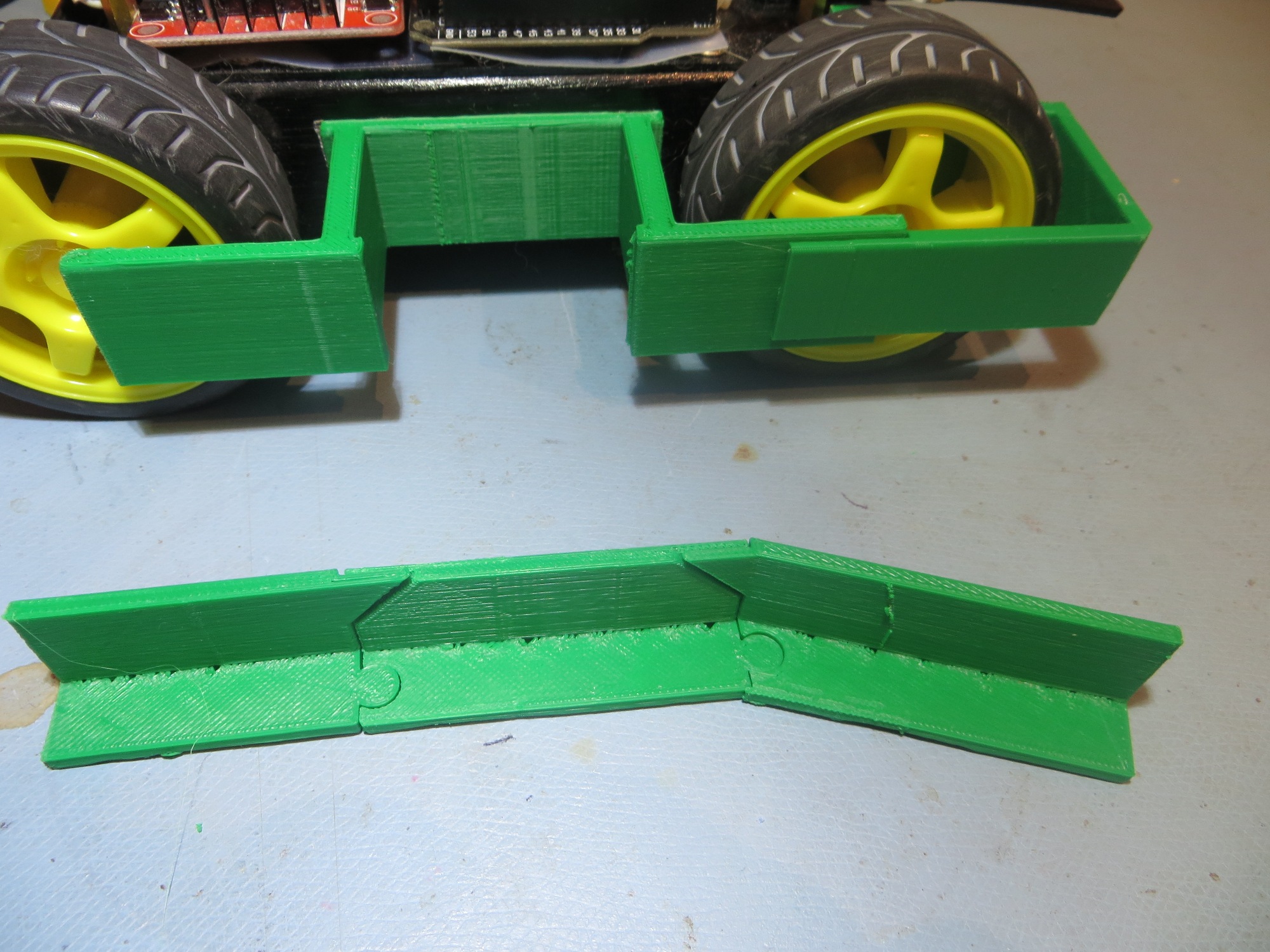
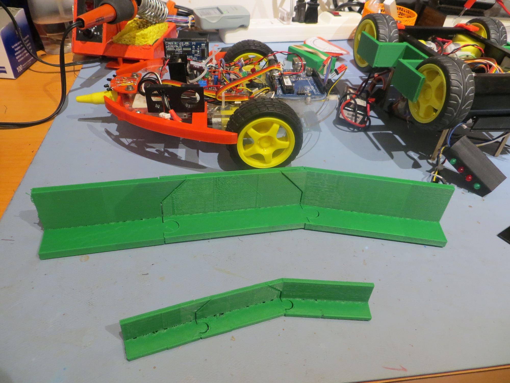
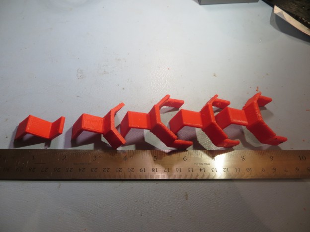
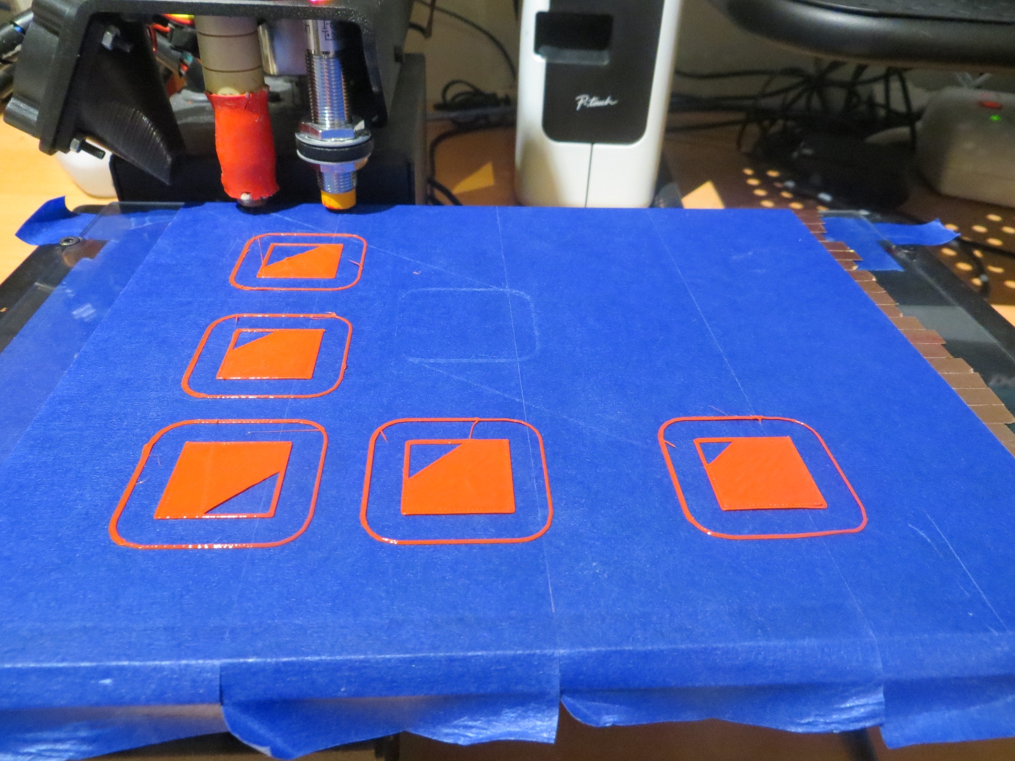
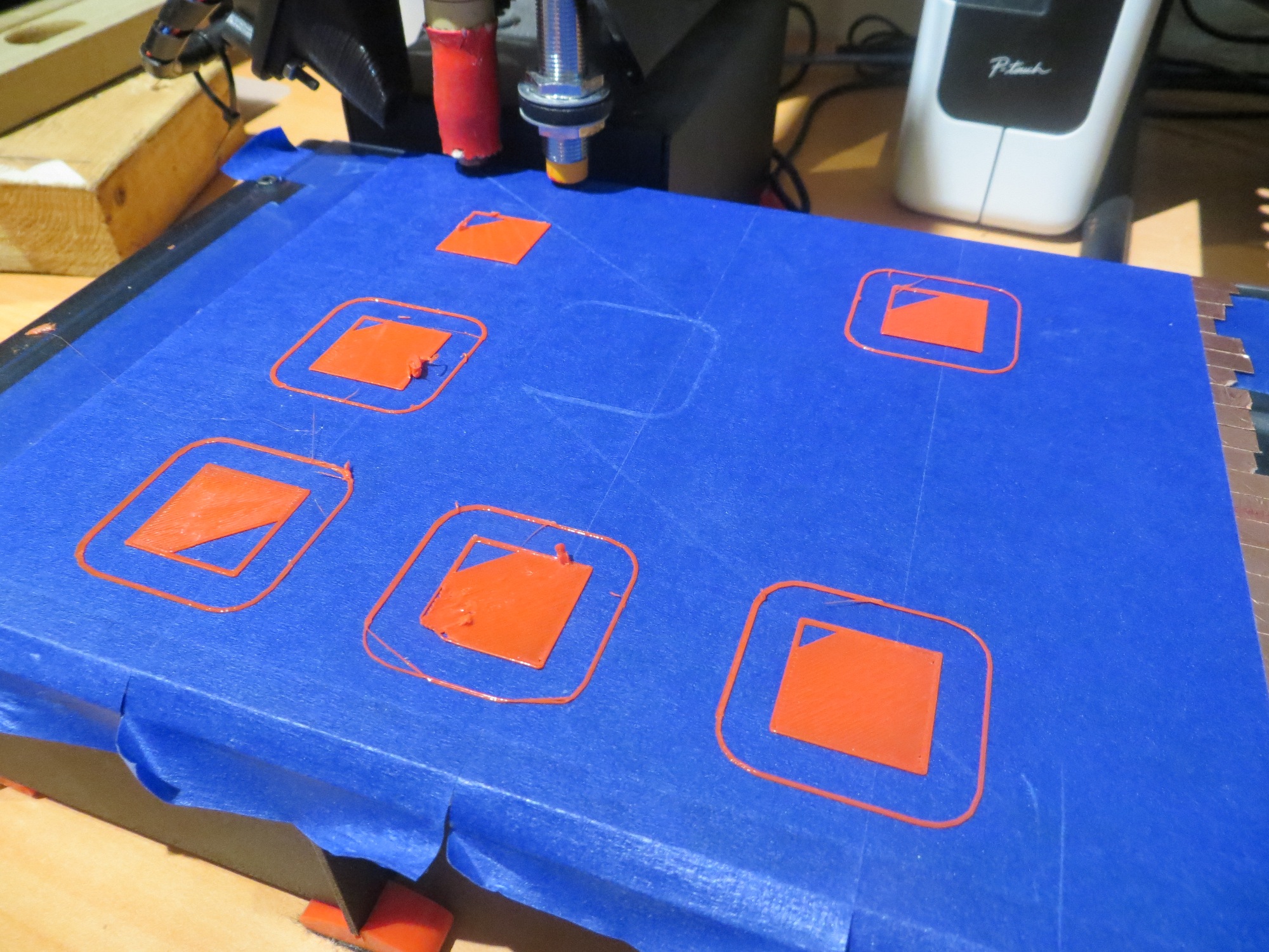
After the usual 2-3 tries to get the printing parameters tuned up (seems they change slightly for every job), I got a very good print, as shown in the following photo
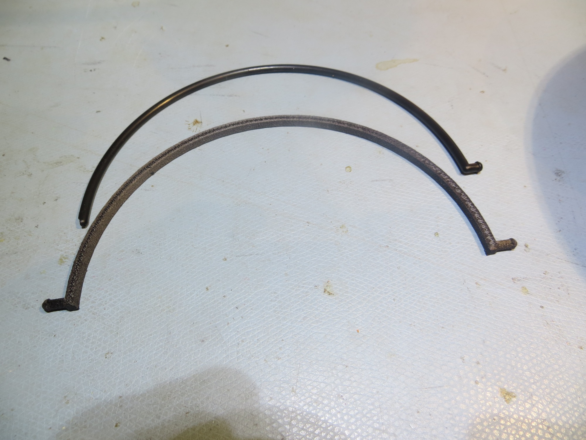
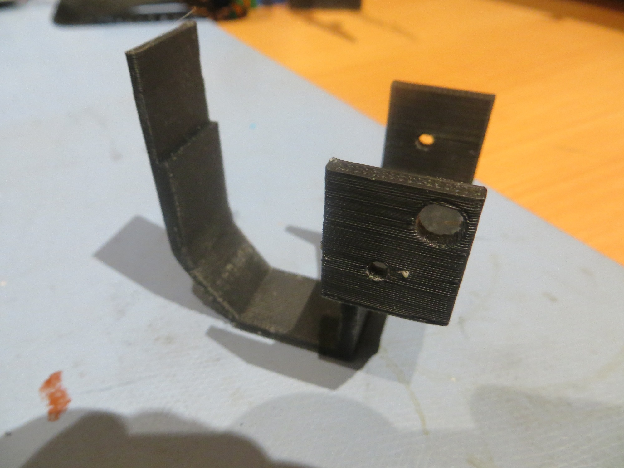
Broken handle and CF-PETG replacement. I only went through about 4 iterations over a few hours to get this right
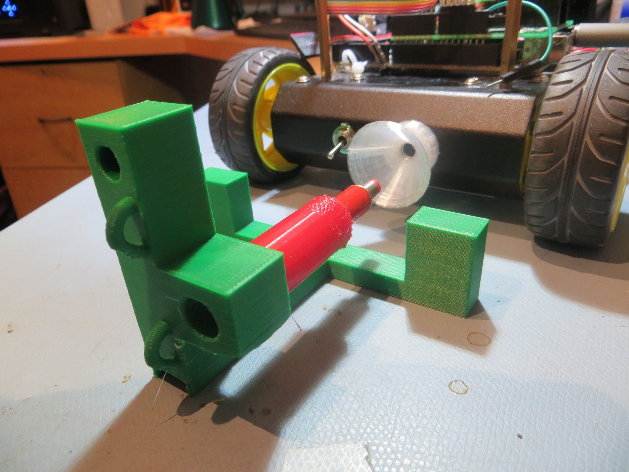
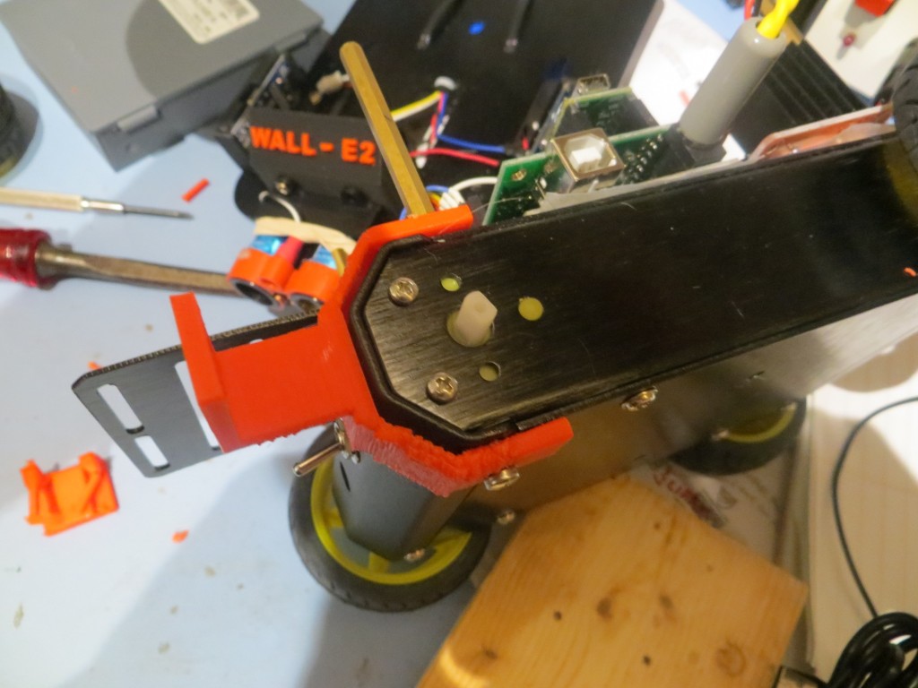
When installed on the coffee pot filter holder, it seemed to work very well – it allows me to pick up the holder by the ‘milk pail handle’ and it also stows away just like the original – yay!!
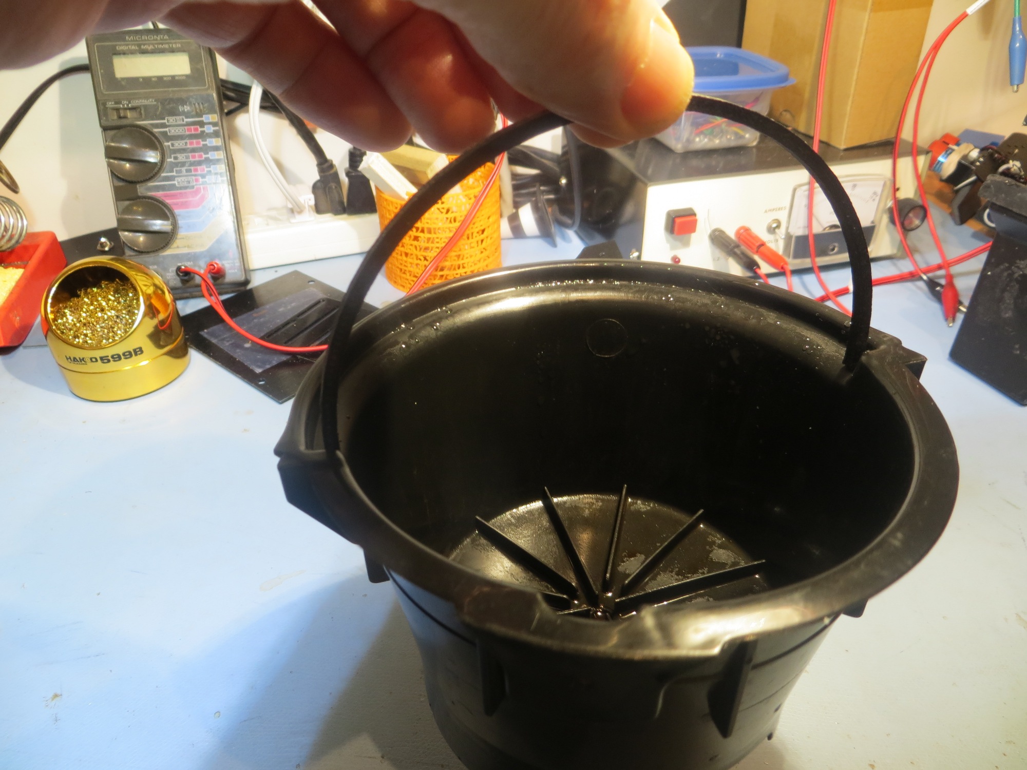
Replacement handle in action – lifting the filter holder as intended
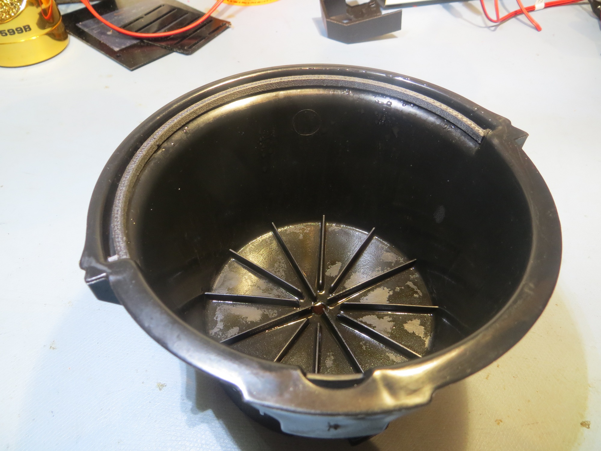
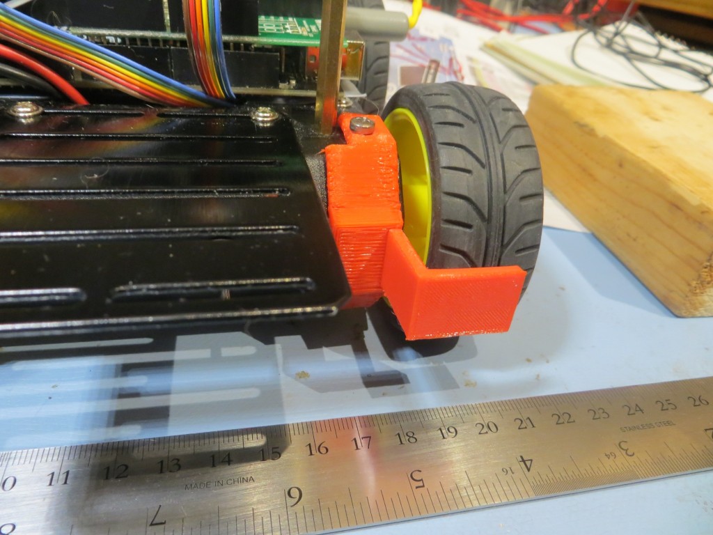
Replacement handle in stowed position
B3DP (Before 3D Printers), it would basically have been impossible to repair this part. Now, that’s not really a disaster, as it is perfectly feasible to use the holder forever without the little ‘milk pail handle’ but if you are a guy like me who hates defective equipment, this would have been a burr under my saddle every time I used the coffee pot. I might have been able to find a replacement part somewhere, at some exorbitant cost (probably more than the entire coffee brewer) with a 6 week delivery lag time, but that would just be a choice between two bad options; deal with a broken system every day, or just buy another brewer because of the failure of some 10-cent part 🙁
However, with my new 3D printer super power, the cost to repair is a few pennies of filament and a few hours of my time in my lab, which I love to do anyway – such a deal! 😉
Stay tuned!
Frank