12087: Top of loop() - calling UpdateAllEnvironmentParameters()
Battery Voltage = 8.26
IRHomingValTotalAvg = 62
12105: glLeftCenterCm = -2097152000 glRightCenterCm = 0
glLeftCenterCm <= glRightCenterCm --> Calling TrackLeftWallOffset()
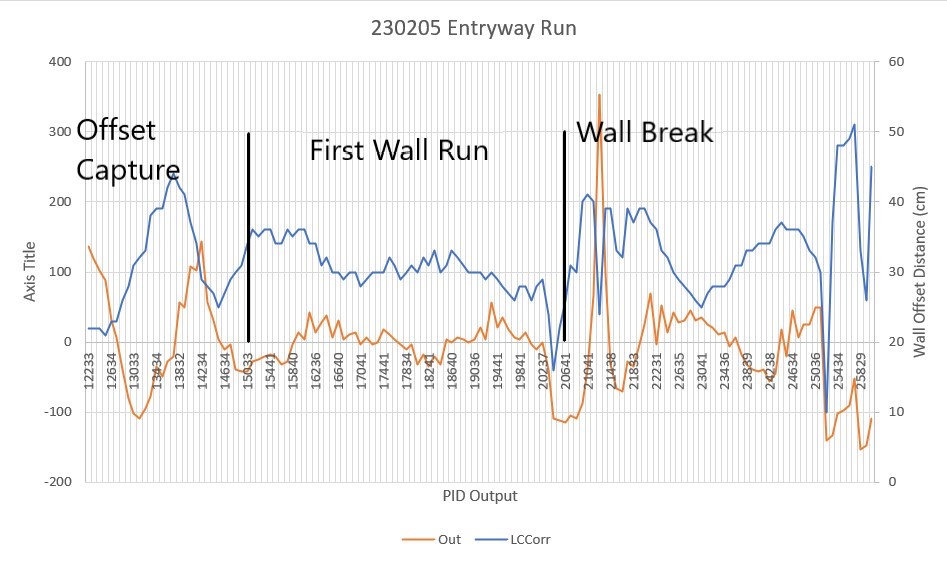
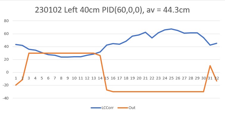
TrackLeftWallOffset: Start tracking offset of 40cm with Kp/Ki/Kd = 350.00 0.00 0.00
Msec LF LC LR RF RC RR F Fvar R Rvar Steer Set Output LSpd RSpd IRAvg
WallE3_Complete_V1.ino: In TrackLeftWallOffset: before while with errcode = NO_ANOMALIES
Msec LF LC LR LCCorr Steer Tweak OffCm Err LastI LastD Out Lspd Rspd
12233 24.00 22.00 24.00 22.00 -0.03 -0.36 0.00 0.39 0.00 0.39 136.50 127 0
12333 24.00 22.00 24.00 22.00 0.02 -0.36 0.00 0.34 0.00 -0.05 119.00 127 0
12440 24.00 22.00 23.00 22.00 0.07 -0.36 0.00 0.29 0.00 -0.05 101.50 127 0
12533 24.00 22.00 23.00 21.00 0.13 -0.38 0.00 0.25 0.00 -0.04 87.50 127 0
12634 26.00 25.00 24.00 23.00 0.25 -0.34 0.00 0.09 0.00 -0.16 31.50 106 43
12732 28.00 27.00 25.00 23.00 0.32 -0.34 0.00 0.02 0.00 -0.07 7.00 82 68
12835 34.00 33.00 30.00 26.00 0.39 -0.28 0.00 -0.11 0.00 -0.13 -38.50 36 113
12932 39.00 39.00 35.00 28.00 0.47 -0.24 0.00 -0.23 0.00 -0.12 -80.50 0 127
13033 42.00 43.00 37.00 31.00 0.47 -0.18 0.00 -0.29 0.00 -0.06 -101.50 0 127
13136 43.00 44.00 38.00 32.00 0.47 -0.16 0.00 -0.31 0.00 -0.02 -108.50 0 127
13237 43.00 43.00 38.00 33.00 0.41 -0.14 0.00 -0.27 0.00 0.04 -94.50 0 127
13336 41.00 42.00 38.00 38.00 0.26 -0.04 0.00 -0.22 0.00 0.05 -77.00 0 127
13434 40.00 40.00 39.00 39.00 0.12 -0.02 0.00 -0.10 0.00 0.12 -35.00 40 110
13534 39.00 41.00 38.00 39.00 0.16 -0.02 0.00 -0.14 0.00 -0.04 -49.00 26 124
13633 41.00 42.00 41.00 42.00 0.04 0.04 0.00 -0.08 0.00 0.06 -28.00 47 103
13730 42.00 44.00 43.00 44.00 -0.02 0.08 0.00 -0.06 0.00 0.02 -21.00 54 96
13832 42.00 45.00 44.00 42.00 -0.20 0.04 0.00 0.16 0.00 0.22 56.00 127 19
13934 41.00 43.00 42.00 41.00 -0.16 0.02 0.00 0.14 0.00 -0.02 49.00 124 26
14029 38.00 41.00 41.00 37.00 -0.25 -0.06 0.00 0.31 0.00 0.17 108.50 127 0
14134 34.00 36.00 36.00 34.00 -0.17 -0.12 0.00 0.29 0.00 -0.02 101.50 127 0
14234 31.00 31.00 33.00 29.00 -0.19 -0.22 0.00 0.41 0.00 0.12 143.50 127 0
14341 30.00 28.00 29.00 28.00 0.08 -0.24 0.00 0.16 0.00 -0.25 56.00 127 19
14438 30.00 28.00 28.00 27.00 0.17 -0.26 0.00 0.09 0.00 -0.07 31.50 106 43
14533 30.00 29.00 27.00 25.00 0.29 -0.30 0.00 0.01 0.00 -0.08 3.50 78 71
14634 32.00 31.00 29.00 27.00 0.29 -0.26 0.00 -0.03 0.00 -0.04 -10.50 64 85
14733 33.00 32.00 30.00 29.00 0.23 -0.22 0.00 -0.01 0.00 0.02 -3.50 71 78
14837 34.00 35.00 32.00 30.00 0.31 -0.20 0.00 -0.11 0.00 -0.10 -38.50 36 113
14934 35.00 36.00 32.00 31.00 0.30 -0.18 0.00 -0.12 0.00 -0.01 -42.00 33 117
15033 36.00 37.00 34.00 34.00 0.24 -0.12 0.00 -0.12 0.00 0.00 -42.00 33 117
15134 36.00 37.00 35.00 36.00 0.16 -0.08 0.00 -0.08 0.00 0.04 -28.00 47 103
15236 37.00 37.00 35.00 35.00 0.17 -0.10 0.00 -0.07 0.00 0.01 -24.50 50 99
15335 36.00 37.00 35.00 36.00 0.14 -0.08 0.00 -0.06 0.00 0.01 -21.00 54 96
15441 37.00 37.00 35.00 36.00 0.13 -0.08 0.00 -0.05 0.00 0.01 -17.50 57 92
15541 37.00 36.00 35.00 34.00 0.18 -0.12 0.00 -0.06 0.00 -0.01 -21.00 53 96
15641 37.00 37.00 35.00 34.00 0.21 -0.12 0.00 -0.09 0.00 -0.03 -31.50 43 106
15738 37.00 37.00 35.00 36.00 0.16 -0.08 0.00 -0.08 0.00 0.01 -28.00 47 103
15840 36.00 36.00 35.00 35.00 0.11 -0.10 0.00 -0.01 0.00 0.07 -3.50 71 78
15934 36.00 36.00 36.00 36.00 0.04 -0.08 0.00 0.04 0.00 0.05 14.00 89 61
16041 35.00 36.00 34.00 36.00 0.07 -0.08 0.00 0.01 0.00 -0.03 3.50 78 71
16137 34.00 34.00 34.00 34.00 0.00 -0.12 0.00 0.12 0.00 0.11 42.00 117 33
16236 34.00 34.00 33.00 34.00 0.08 -0.12 0.00 0.04 0.00 -0.08 14.00 89 61
16338 33.00 32.00 32.00 31.00 0.10 -0.18 0.00 0.08 0.00 0.04 28.00 103 47
16441 32.00 32.00 32.00 32.00 0.05 -0.16 0.00 0.11 0.00 0.03 38.50 113 36
16538 32.00 32.00 30.00 30.00 0.18 -0.20 0.00 0.02 0.00 -0.09 7.00 82 68
16640 31.00 31.00 30.00 30.00 0.11 -0.20 0.00 0.09 0.00 0.07 31.50 106 43
16741 32.00 31.00 29.00 29.00 0.21 -0.22 0.00 0.01 0.00 -0.08 3.50 78 71
16841 31.00 31.00 30.00 30.00 0.17 -0.20 0.00 0.03 0.00 0.02 10.50 85 64
16941 31.00 31.00 30.00 30.00 0.16 -0.20 0.00 0.04 0.00 0.01 14.00 89 61
17041 32.00 31.00 29.00 28.00 0.25 -0.24 0.00 -0.01 0.00 -0.05 -3.50 71 78
17140 31.00 31.00 29.00 29.00 0.20 -0.22 0.00 0.02 0.00 0.03 7.00 82 68
17241 32.00 32.00 30.00 30.00 0.21 -0.20 0.00 -0.01 0.00 -0.03 -3.50 71 78
17340 32.00 32.00 30.00 30.00 0.20 -0.20 0.00 0.00 0.00 0.01 0.00 75 75
17441 31.00 31.00 30.00 30.00 0.15 -0.20 0.00 0.05 0.00 0.05 17.50 92 57
17541 32.00 33.00 30.00 32.00 0.13 -0.16 0.00 0.03 0.00 -0.02 10.50 85 64
17631 32.00 32.00 31.00 31.00 0.17 -0.18 0.00 0.01 0.00 -0.02 3.50 78 71
17736 33.00 32.00 30.00 29.00 0.23 -0.22 0.00 -0.01 0.00 -0.02 -3.50 71 78
17834 33.00 33.00 31.00 30.00 0.23 -0.20 0.00 -0.03 0.00 -0.02 -10.50 64 85
17932 33.00 33.00 31.00 31.00 0.19 -0.18 0.00 -0.01 0.00 0.02 -3.50 71 78
18034 34.00 34.00 31.00 30.00 0.29 -0.20 0.00 -0.09 0.00 -0.08 -31.50 43 106
18132 33.00 34.00 31.00 32.00 0.21 -0.16 0.00 -0.05 0.00 0.04 -17.50 57 92
18241 34.00 35.00 31.00 31.00 0.28 -0.18 0.00 -0.10 0.00 -0.05 -35.00 40 110
18341 34.00 35.00 32.00 33.00 0.20 -0.14 0.00 -0.06 0.00 0.04 -21.00 54 96
18441 34.00 34.00 31.00 30.00 0.29 -0.20 0.00 -0.09 0.00 -0.03 -31.50 43 106
18541 33.00 33.00 32.00 31.00 0.17 -0.18 0.00 0.01 0.00 0.10 3.50 78 71
18640 33.00 34.00 32.00 33.00 0.14 -0.14 0.00 0.00 0.00 -0.01 0.00 75 75
18734 33.00 33.00 32.00 32.00 0.14 -0.16 0.00 0.02 0.00 0.02 7.00 82 68
18840 32.00 33.00 30.00 31.00 0.17 -0.18 0.00 0.01 0.00 -0.01 3.50 78 71
18938 32.00 32.00 30.00 30.00 0.20 -0.20 0.00 0.00 0.00 -0.01 0.00 75 75
19036 31.00 32.00 29.00 30.00 0.19 -0.20 0.00 0.01 0.00 0.01 3.50 78 71
19138 31.00 31.00 29.00 30.00 0.14 -0.20 0.00 0.06 0.00 0.05 21.00 96 54
19240 31.00 31.00 28.00 29.00 0.21 -0.22 0.00 0.01 0.00 -0.05 3.50 78 71
19341 30.00 30.00 29.00 30.00 0.04 -0.20 0.00 0.16 0.00 0.15 56.00 127 19
19441 29.00 30.00 28.00 29.00 0.16 -0.22 0.00 0.06 0.00 -0.10 21.00 96 54
19541 28.00 29.00 27.00 28.00 0.14 -0.24 0.00 0.10 0.00 0.04 35.00 110 40
19641 29.00 29.00 27.00 27.00 0.21 -0.26 0.00 0.05 0.00 -0.05 17.50 92 57
19741 29.00 29.00 26.00 26.00 0.26 -0.28 0.00 0.02 0.00 -0.03 7.00 82 68
19841 29.00 30.00 27.00 28.00 0.23 -0.24 0.00 0.01 0.00 -0.01 3.50 78 71
19941 29.00 30.00 27.00 28.00 0.20 -0.24 0.00 0.04 0.00 0.03 14.00 89 61
20041 30.00 30.00 27.00 26.00 0.29 -0.28 0.00 -0.01 0.00 -0.05 -3.50 71 78
20141 30.00 31.00 27.00 28.00 0.27 -0.24 0.00 -0.03 0.00 -0.02 -10.50 64 85
20237 30.00 31.00 28.00 29.00 0.22 -0.22 0.00 0.00 0.00 0.03 0.00 75 75
20337 33.00 32.00 29.00 24.00 0.43 -0.32 0.00 -0.11 0.00 -0.11 -38.50 36 113
20441 38.00 39.00 30.00 16.00 0.79 -0.48 0.00 -0.31 0.00 -0.20 -108.50 0 127
20541 40.00 42.00 33.00 22.00 0.68 -0.36 0.00 -0.32 0.00 -0.01 -112.00 0 127
20641 43.00 45.00 37.00 26.00 0.61 -0.28 0.00 -0.33 0.00 -0.01 -115.50 0 127
20734 43.00 44.00 38.00 31.00 0.48 -0.18 0.00 -0.30 0.00 0.03 -105.00 0 127
20832 42.00 44.00 37.00 30.00 0.51 -0.20 0.00 -0.31 0.00 -0.01 -108.50 0 127
20933 40.00 44.00 37.00 40.00 0.25 0.00 0.00 -0.25 0.00 0.06 -87.50 0 127
21041 39.00 42.00 38.00 41.00 0.09 0.02 0.00 -0.11 0.00 0.14 -38.50 36 113
21140 40.00 42.00 41.00 40.00 -0.19 0.00 0.00 0.19 0.00 0.30 66.50 127 8
21233 43.00 48.00 50.00 24.00 -0.69 -0.32 0.00 1.01 0.00 0.82 353.50 127 0
21336 40.00 43.00 42.00 39.00 -0.26 -0.02 0.00 0.28 0.00 -0.73 98.00 127 0
21438 38.00 40.00 36.00 39.00 0.11 -0.02 0.00 -0.09 0.00 -0.37 -31.50 43 106
21538 38.00 39.00 35.00 33.00 0.33 -0.14 0.00 -0.19 0.00 -0.10 -66.50 8 127
21639 38.00 39.00 35.00 32.00 0.36 -0.16 0.00 -0.20 0.00 -0.01 -70.00 4 127
21740 37.00 40.00 36.00 39.00 0.10 -0.02 0.00 -0.08 0.00 0.12 -28.00 47 103
21833 38.00 39.00 36.00 37.00 0.16 -0.06 0.00 -0.10 0.00 -0.02 -35.00 40 110
21931 37.00 39.00 37.00 39.00 0.03 -0.02 0.00 -0.01 0.00 0.09 -3.50 71 78
22031 36.00 39.00 37.00 39.00 -0.05 -0.02 0.00 0.07 0.00 0.08 24.50 99 50
22133 34.00 38.00 35.00 37.00 -0.14 -0.06 0.00 0.20 0.00 0.13 70.00 127 5
22231 34.00 36.00 33.00 36.00 0.09 -0.08 0.00 -0.01 0.00 -0.21 -3.50 71 78
22335 32.00 33.00 32.00 33.00 -0.01 -0.14 0.00 0.15 0.00 0.16 52.50 127 22
22432 31.00 33.00 30.00 32.00 0.12 -0.16 0.00 0.04 0.00 -0.11 14.00 89 61
22532 29.00 30.00 28.00 30.00 0.08 -0.20 0.00 0.12 0.00 0.08 42.00 117 33
22635 29.00 30.00 28.00 29.00 0.14 -0.22 0.00 0.08 0.00 -0.04 28.00 103 47
22734 28.00 29.00 26.00 28.00 0.15 -0.24 0.00 0.09 0.00 0.01 31.50 106 43
22841 27.00 28.00 25.00 27.00 0.13 -0.26 0.00 0.13 0.00 0.04 45.50 120 29
22940 26.00 28.00 25.00 26.00 0.19 -0.28 0.00 0.09 0.00 -0.04 31.50 106 43
23041 27.00 27.00 25.00 25.00 0.20 -0.30 0.00 0.10 0.00 0.01 35.00 110 39
23141 26.00 29.00 24.00 27.00 0.19 -0.26 0.00 0.07 0.00 -0.03 24.50 99 50
23241 27.00 29.00 25.00 28.00 0.18 -0.24 0.00 0.06 0.00 -0.01 21.00 96 54
23341 28.00 30.00 26.00 28.00 0.21 -0.24 0.00 0.03 0.00 -0.03 10.50 85 64
23436 28.00 30.00 26.00 28.00 0.20 -0.24 0.00 0.04 0.00 0.01 14.00 89 61
23541 30.00 32.00 27.00 29.00 0.24 -0.22 0.00 -0.02 0.00 -0.06 -7.00 68 82
23641 31.00 32.00 29.00 31.00 0.16 -0.18 0.00 0.02 0.00 0.04 7.00 82 68
23737 32.00 34.00 30.00 31.00 0.23 -0.18 0.00 -0.05 0.00 -0.07 -17.50 57 92
23839 32.00 36.00 30.00 33.00 0.23 -0.14 0.00 -0.09 0.00 -0.04 -31.50 43 106
23935 33.00 36.00 31.00 33.00 0.25 -0.14 0.00 -0.11 0.00 -0.02 -38.50 36 113
24041 34.00 37.00 32.00 34.00 0.24 -0.12 0.00 -0.12 0.00 -0.01 -42.00 33 117
24141 34.00 37.00 32.00 34.00 0.23 -0.12 0.00 -0.11 0.00 0.01 -38.50 36 113
24238 35.00 38.00 32.00 34.00 0.28 -0.12 0.00 -0.16 0.00 -0.05 -56.00 19 127
24337 34.00 39.00 32.00 36.00 0.21 -0.08 0.00 -0.13 0.00 0.03 -45.50 29 120
24432 35.00 37.00 35.00 37.00 0.01 -0.06 0.00 0.05 0.00 0.18 17.50 92 57
24531 35.00 37.00 34.00 36.00 0.14 -0.08 0.00 -0.06 0.00 -0.11 -21.00 54 96
24634 34.00 36.00 34.00 36.00 -0.05 -0.08 0.00 0.13 0.00 0.19 45.50 120 29
24736 33.00 36.00 32.00 36.00 0.06 -0.08 0.00 0.02 0.00 -0.11 7.00 82 68
24834 31.00 35.00 31.00 35.00 0.03 -0.10 0.00 0.07 0.00 0.05 24.50 99 50
24934 31.00 33.00 30.00 33.00 0.07 -0.14 0.00 0.07 0.00 0.00 24.50 99 50
25036 29.00 32.00 28.00 32.00 0.02 -0.16 0.00 0.14 0.00 0.07 49.00 124 26
25136 28.00 30.00 27.00 30.00 0.06 -0.20 0.00 0.14 0.00 0.00 49.00 124 26
25234 41.00 41.00 29.00 10.00 1.00 -0.60 0.00 -0.40 0.00 -0.54 -140.00 0 127
25338 45.00 50.00 41.00 37.00 0.44 -0.06 0.00 -0.38 0.00 0.02 -133.00 0 127
25434 45.00 49.00 43.00 48.00 0.13 0.16 0.00 -0.29 0.00 0.09 -101.50 0 127
25535 44.00 49.00 43.00 48.00 0.12 0.16 0.00 -0.28 0.00 0.01 -98.00 0 127
25635 45.00 50.00 44.00 49.00 0.08 0.18 0.00 -0.26 0.00 0.02 -91.00 0 127
25731 48.00 51.00 49.00 51.00 -0.07 0.22 0.00 -0.15 0.00 0.11 -52.50 22 127
25829 51.00 54.00 45.00 33.00 0.58 -0.14 0.00 -0.44 0.00 -0.29 -154.00 0 127
25931 50.00 52.00 43.00 26.00 0.70 -0.28 0.00 -0.42 0.00 0.02 -147.00 0 127
26029 44.00 48.00 42.00 45.00 0.21 0.10 0.00 -0.31 0.00 0.11 -108.50 0 127
In HandleAnomalousConditions with WALL_OFFSET_DIST_AHEAD error code detected
WALL_OFFSET_DIST_AHEAD case detected with tracking case Left
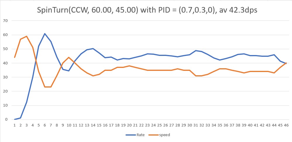
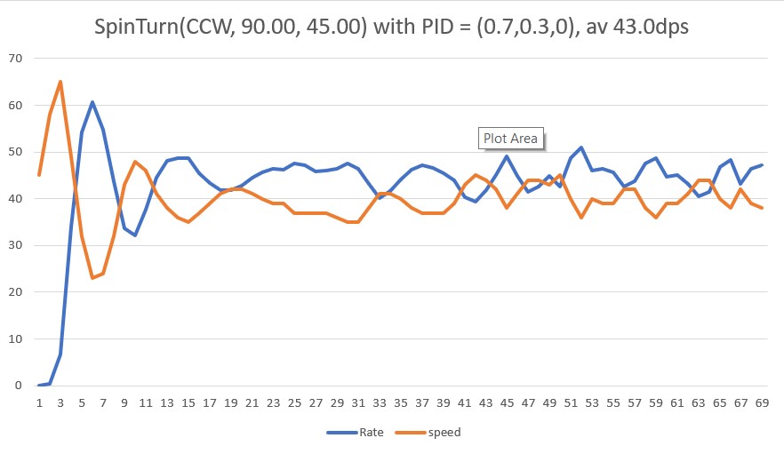
In SpinTurn(CW, 90.00, 45.00) with PID = (0.7,0.3,0.0)
Init hdg = -95.99 deg, Turn = 90.00 deg, tgt = -5.99 deg, timeout = 4.00 sec
Msec Hdg PrvHdg dHdg Rate tgtDPS err Kp*err Ival Kd*Derr speed Match Slope
26094 -100.46 -95.99 -4.47 149.05 45.00 -104.05 -72.84 -31.22 -0.00 0 0.48 0.48
26124 -103.58 -100.46 -3.11 103.73 45.00 -58.73 -41.11 -48.83 0.00 0 0.46 -0.02
26154 -106.23 -103.58 -2.66 88.63 45.00 -43.63 -30.54 -61.92 0.00 0 0.44 -0.01
26184 -107.97 -106.23 -1.74 57.89 45.00 -12.89 -9.02 -65.79 0.00 0 0.43 -0.01
26214 -108.71 -107.97 -0.74 24.58 45.00 20.42 14.30 -59.66 0.00 0 0.43 -0.00
26244 -108.85 -108.71 -0.15 4.85 45.00 40.15 28.10 -47.62 0.00 0 0.43 -0.00
26274 -109.03 -108.85 -0.18 5.90 45.00 39.10 27.37 -35.89 -0.00 0 0.43 -0.00
26304 -109.03 -109.03 0.00 0.02 45.00 44.98 31.48 -22.39 0.00 9 0.43 0.00
26334 -108.99 -109.03 0.04 1.36 45.00 43.64 30.55 -9.30 -0.00 21 0.43 0.00
26364 -108.99 -108.99 0.00 0.08 45.00 44.92 31.45 4.18 0.00 35 0.43 0.00
26394 -108.84 -108.99 0.15 4.90 45.00 40.10 28.07 16.21 -0.00 44 0.43 0.00
26424 -108.54 -108.84 0.30 9.91 45.00 35.09 24.56 26.73 -0.00 51 0.43 0.00
26454 -107.46 -108.54 1.08 36.00 45.00 9.00 6.30 29.43 -0.00 35 0.44 0.01
26484 -105.94 -107.46 1.52 50.79 45.00 -5.79 -4.05 27.70 -0.00 23 0.44 0.01
26517 -104.37 -105.94 1.57 52.18 45.00 -7.18 -5.02 25.54 -0.00 20 0.45 0.01
26547 -102.98 -104.37 1.39 46.34 45.00 -1.34 -0.94 25.14 0.00 24 0.46 0.01
26577 -101.85 -102.98 1.14 37.90 45.00 7.10 4.97 27.27 0.00 32 0.47 0.01
26607 -100.90 -101.85 0.95 31.70 45.00 13.30 9.31 31.26 0.00 40 0.47 0.01
26637 -99.91 -100.90 0.98 32.72 45.00 12.28 8.59 34.94 -0.00 43 0.48 0.01
26667 -98.77 -99.91 1.14 38.01 45.00 6.99 4.90 37.04 -0.00 41 0.48 0.01
26697 -97.38 -98.77 1.39 46.40 45.00 -1.40 -0.98 36.62 -0.00 35 0.49 0.01
26727 -95.87 -97.38 1.51 50.46 45.00 -5.46 -3.82 34.98 -0.00 31 0.50 0.01
26757 -94.36 -95.87 1.51 50.41 45.00 -5.41 -3.79 33.36 0.00 29 0.51 0.01
26787 -92.85 -94.36 1.50 50.06 45.00 -5.06 -3.54 31.84 0.00 28 0.52 0.01
26817 -91.48 -92.85 1.37 45.78 45.00 -0.78 -0.55 31.61 0.00 31 0.53 0.01
26847 -90.20 -91.48 1.28 42.66 45.00 2.34 1.64 32.31 0.00 33 0.53 0.01
26877 -88.96 -90.20 1.24 41.21 45.00 3.79 2.66 33.45 0.00 36 0.54 0.01
26907 -87.73 -88.96 1.23 41.12 45.00 3.88 2.72 34.61 0.00 37 0.55 0.01
26937 -86.44 -87.73 1.29 43.13 45.00 1.87 1.31 35.17 -0.00 36 0.55 0.01
26967 -85.06 -86.44 1.38 45.97 45.00 -0.97 -0.68 34.88 -0.00 34 0.56 0.01
26997 -83.65 -85.06 1.40 46.83 45.00 -1.83 -1.28 34.33 -0.00 33 0.57 0.01
27027 -82.24 -83.65 1.41 47.14 45.00 -2.14 -1.50 33.69 -0.00 32 0.58 0.01
27057 -80.82 -82.24 1.42 47.24 45.00 -2.24 -1.57 33.02 -0.00 31 0.58 0.01
27087 -79.34 -80.82 1.48 49.31 45.00 -4.31 -3.02 31.73 -0.00 28 0.59 0.01
27117 -77.89 -79.34 1.45 48.35 45.00 -3.35 -2.35 30.73 0.00 28 0.60 0.01
27147 -76.50 -77.89 1.40 46.53 45.00 -1.53 -1.07 30.27 0.00 29 0.61 0.01
27177 -75.24 -76.50 1.25 41.74 45.00 3.26 2.28 31.24 0.00 33 0.62 0.01
27207 -74.06 -75.24 1.18 39.37 45.00 5.63 3.94 32.93 0.00 36 0.62 0.01
27237 -72.89 -74.06 1.17 38.97 45.00 6.03 4.22 34.74 0.00 38 0.63 0.01
27267 -71.64 -72.89 1.26 41.91 45.00 3.09 2.16 35.67 -0.00 37 0.64 0.01
27297 -70.21 -71.64 1.43 47.56 45.00 -2.56 -1.79 34.90 -0.00 33 0.64 0.01
27327 -68.60 -70.21 1.61 53.74 45.00 -8.74 -6.12 32.28 -0.00 26 0.65 0.01
27357 -66.99 -68.60 1.60 53.45 45.00 -8.45 -5.92 29.74 0.00 23 0.66 0.01
27387 -65.66 -66.99 1.33 44.39 45.00 0.61 0.42 29.92 0.00 30 0.67 0.01
27417 -64.52 -65.66 1.15 38.21 45.00 6.79 4.75 31.96 0.00 36 0.67 0.01
27447 -63.41 -64.52 1.11 36.90 45.00 8.10 5.67 34.39 0.00 40 0.68 0.01
27477 -62.24 -63.41 1.17 39.09 45.00 5.91 4.14 36.16 -0.00 40 0.69 0.01
27507 -60.97 -62.24 1.26 42.15 45.00 2.85 1.99 37.02 -0.00 39 0.69 0.01
27537 -59.56 -60.97 1.41 47.01 45.00 -2.01 -1.41 36.41 -0.00 35 0.70 0.01
27567 -58.01 -59.56 1.55 51.59 45.00 -6.59 -4.62 34.43 -0.00 29 0.71 0.01
27597 -56.47 -58.01 1.54 51.45 45.00 -6.45 -4.52 32.50 0.00 27 0.72 0.01
27627 -55.06 -56.47 1.41 46.98 45.00 -1.98 -1.39 31.90 0.00 30 0.73 0.01
27657 -53.70 -55.06 1.36 45.28 45.00 -0.28 -0.20 31.82 0.00 31 0.73 0.01
27687 -52.42 -53.70 1.29 42.85 45.00 2.15 1.50 32.46 0.00 33 0.74 0.01
27717 -51.17 -52.42 1.25 41.62 45.00 3.38 2.37 33.48 0.00 35 0.75 0.01
27747 -49.87 -51.17 1.30 43.25 45.00 1.75 1.23 34.00 -0.00 35 0.76 0.01
27777 -48.55 -49.87 1.32 43.91 45.00 1.09 0.76 34.33 -0.00 35 0.76 0.01
27807 -47.18 -48.55 1.37 45.83 45.00 -0.83 -0.58 34.08 -0.00 33 0.77 0.01
27837 -45.75 -47.18 1.43 47.56 45.00 -2.56 -1.79 33.31 -0.00 31 0.78 0.01
27867 -44.35 -45.75 1.40 46.76 45.00 -1.76 -1.23 32.79 0.00 31 0.79 0.01
27897 -42.98 -44.35 1.37 45.67 45.00 -0.67 -0.47 32.59 0.00 32 0.79 0.01
27927 -41.64 -42.98 1.34 44.66 45.00 0.34 0.24 32.69 0.00 32 0.80 0.01
27957 -40.38 -41.64 1.26 42.00 45.00 3.00 2.10 33.59 0.00 35 0.81 0.01
27987 -39.09 -40.38 1.29 43.00 45.00 2.00 1.40 34.19 -0.00 35 0.82 0.01
28017 -37.77 -39.09 1.32 43.87 45.00 1.13 0.79 34.52 -0.00 35 0.82 0.01
28047 -36.43 -37.77 1.34 44.76 45.00 0.24 0.17 34.60 -0.00 34 0.83 0.01
28077 -35.04 -36.43 1.38 46.14 45.00 -1.14 -0.80 34.25 -0.00 33 0.84 0.01
28107 -33.68 -35.04 1.37 45.66 45.00 -0.66 -0.46 34.05 0.00 33 0.85 0.01
28137 -32.40 -33.68 1.27 42.36 45.00 2.64 1.85 34.85 0.00 36 0.85 0.01
28167 -31.14 -32.40 1.27 42.27 45.00 2.73 1.91 35.67 0.00 37 0.86 0.01
28197 -29.83 -31.14 1.30 43.40 45.00 1.60 1.12 36.15 -0.00 37 0.87 0.01
28227 -28.38 -29.83 1.45 48.40 45.00 -3.40 -2.38 35.13 -0.00 32 0.88 0.01
28257 -26.85 -28.38 1.53 51.08 45.00 -6.08 -4.26 33.30 -0.00 29 0.88 0.01
28287 -25.38 -26.85 1.47 48.84 45.00 -3.84 -2.69 32.15 0.00 29 0.89 0.01
28317 -24.01 -25.38 1.37 45.74 45.00 -0.74 -0.52 31.93 0.00 31 0.90 0.01
28347 -22.68 -24.01 1.33 44.28 45.00 0.72 0.50 32.15 0.00 32 0.91 0.01
28377 -21.40 -22.68 1.28 42.68 45.00 2.32 1.62 32.84 0.00 34 0.91 0.01
28407 -20.12 -21.40 1.28 42.62 45.00 2.38 1.66 33.55 0.00 35 0.92 0.01
28437 -18.80 -20.12 1.32 44.10 45.00 0.90 0.63 33.82 -0.00 34 0.93 0.01
28467 -17.43 -18.80 1.37 45.64 45.00 -0.64 -0.45 33.63 -0.00 33 0.94 0.01
28497 -16.02 -17.43 1.42 47.22 45.00 -2.22 -1.55 32.96 -0.00 31 0.94 0.01
28527 -14.61 -16.02 1.40 46.83 45.00 -1.83 -1.28 32.41 0.00 31 0.95 0.01
28557 -13.23 -14.61 1.38 46.07 45.00 -1.07 -0.75 32.09 0.00 31 0.96 0.01
28587 -11.94 -13.23 1.29 42.89 45.00 2.11 1.48 32.73 0.00 34 0.97 0.01
28617 -10.72 -11.94 1.22 40.83 45.00 4.17 2.92 33.98 0.00 36 0.97 0.01
28647 -9.42 -10.72 1.29 43.09 45.00 1.91 1.34 34.55 -0.00 35 0.98 0.01
28677 -8.01 -9.42 1.41 47.03 45.00 -2.03 -1.42 33.94 -0.00 32 0.99 0.01
28707 -6.65 -8.01 1.37 45.62 45.00 -0.62 -0.43 33.76 0.00 33 1.00 0.01
average turn rate = 43.7
28710: Top of loop() - calling UpdateAllEnvironmentParameters()
Battery Voltage = 8.06
IRHomingValTotalAvg = 98
28732: glLeftCenterCm = -2080374784 glRightCenterCm = 0
glLeftCenterCm <= glRightCenterCm --> Calling TrackLeftWallOffset()
TrackLeftWallOffset: Start tracking offset of 40cm with Kp/Ki/Kd = 350.00 0.00 0.00
Msec LF LC LR RF RC RR F Fvar R Rvar Steer Set Output LSpd RSpd IRAvg
WallE3_Complete_V1.ino: In TrackLeftWallOffset: before while with errcode = NO_ANOMALIES
Msec LF LC LR LCCorr Steer Tweak OffCm Err LastI LastD Out Lspd Rspd
28859 35.00 38.00 32.00 31.00 0.36 -0.18 0.00 -0.18 0.00 -0.18 -63.00 11 127
28959 35.00 38.00 32.00 34.00 0.27 -0.12 0.00 -0.15 0.00 0.03 -52.50 22 127
29059 34.00 38.00 31.00 33.00 0.31 -0.14 0.00 -0.17 0.00 -0.02 -59.50 15 127
29159 34.00 37.00 32.00 35.00 0.19 -0.10 0.00 -0.09 0.00 0.08 -31.50 43 106
29264 33.00 36.00 32.00 35.00 0.13 -0.10 0.00 -0.03 0.00 0.06 -10.50 64 85
29367 33.00 36.00 33.00 36.00 0.06 -0.08 0.00 0.02 0.00 0.05 7.00 82 68
29467 34.00 36.00 33.00 35.00 0.13 -0.10 0.00 -0.03 0.00 -0.05 -10.50 64 85
29567 33.00 36.00 32.00 35.00 0.10 -0.10 0.00 0.00 0.00 0.03 0.00 75 75
29666 33.00 35.00 32.00 35.00 0.07 -0.10 0.00 0.03 0.00 0.03 10.50 85 64
29767 32.00 35.00 32.00 35.00 0.05 -0.10 0.00 0.05 0.00 0.02 17.50 92 57
29862 32.00 35.00 30.00 33.00 0.17 -0.14 0.00 -0.03 0.00 -0.08 -10.50 64 85
29962 31.00 34.00 30.00 34.00 0.08 -0.12 0.00 0.04 0.00 0.07 14.00 89 61
30065 25.00 29.00 29.00 21.00 -0.47 -0.38 0.00 0.85 0.00 0.81 297.50 127 0
30164 22.00 23.00 25.00 21.00 -0.26 -0.38 0.00 0.64 0.00 -0.21 224.00 127 0
30267 24.00 26.00 22.00 24.00 0.20 -0.32 0.00 0.12 0.00 -0.52 42.00 117 33
30366 26.00 27.00 24.00 26.00 0.18 -0.28 0.00 0.10 0.00 -0.02 35.00 110 40
30462 25.00 28.00 24.00 28.00 0.09 -0.24 0.00 0.15 0.00 0.05 52.50 127 22
30564 29.00 35.00 25.00 28.00 0.38 -0.24 0.00 -0.14 0.00 -0.29 -49.00 26 124
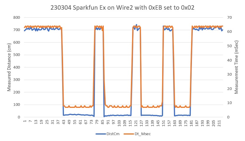
30661 749.00 824.00 705.00 207.00 1.00 3.34 0.00 -4.34 0.00 -4.20 -1519.00 0 127
30762 749.00 824.00 705.00 207.00 1.00 3.34 0.00 -4.34 0.00 0.00 -1519.00 0 127
30866 749.00 824.00 705.00 207.00 1.00 3.34 0.00 -4.34 0.00 0.00 -1519.00 0 127
30965 749.00 824.00 705.00 207.00 1.00 3.34 0.00 -4.34 0.00 0.00 -1519.00 0 127
31067 749.00 824.00 705.00 207.00 1.00 3.34 0.00 -4.34 0.00 0.00 -1519.00 0 127
31161 749.00 824.00 47.00 207.00 1.00 3.34 0.00 -4.34 0.00 0.00 -1519.00 0 127
31258 55.00 58.00 48.00 32.00 0.65 -0.16 0.00 -0.49 0.00 3.85 -171.50 0 127
31359 49.00 49.00 43.00 33.00 0.52 -0.14 0.00 -0.38 0.00 0.11 -133.00 0 127
31460 46.00 50.00 48.00 45.00 -0.26 0.10 0.00 0.16 0.00 0.54 56.00 127 19
31556 52.00 58.00 56.00 44.00 -0.43 0.08 0.00 0.35 0.00 0.19 122.50 127 0
31660 53.00 57.00 55.00 54.00 -0.19 0.28 0.00 -0.09 0.00 -0.44 -31.50 43 106
31757 46.00 50.00 48.00 46.00 -0.23 0.12 0.00 0.11 0.00 0.20 38.50 113 36
31861 43.00 47.00 44.00 46.00 -0.11 0.12 0.00 -0.01 0.00 -0.12 -3.50 71 78
31959 48.00 50.00 43.00 34.00 0.50 -0.12 0.00 -0.38 0.00 -0.37 -133.00 0 127
32056 49.00 53.00 44.00 36.00 0.50 -0.08 0.00 -0.42 0.00 -0.04 -147.00 0 127
32160 50.00 53.00 47.00 46.00 0.30 0.12 0.00 -0.42 0.00 0.00 -147.00 0 127
32259 50.00 53.00 48.00 48.00 0.25 0.16 0.00 -0.41 0.00 0.01 -143.50 0 127
32357 50.00 54.00 47.00 48.00 0.26 0.16 0.00 -0.42 0.00 -0.01 -147.00 0 127
32458 49.00 53.00 48.00 52.00 0.11 0.24 0.00 -0.35 0.00 0.07 -122.50 0 127
32558 49.00 53.00 49.00 53.00 0.02 0.26 0.00 -0.28 0.00 0.07 -98.00 0 127
32658 50.00 56.00 705.00 14.00 -1.00 -0.52 0.00 1.52 0.00 1.80 532.00 127 0
32762 749.00 824.00 705.00 207.00 1.00 3.34 0.00 -4.34 0.00 -5.86 -1519.00 0 127
32858 45.00 824.00 705.00 207.00 -1.00 3.34 0.00 -2.34 0.00 2.00 -819.00 0 127
32956 50.00 56.00 705.00 14.00 -1.00 -0.52 0.00 1.52 0.00 3.86 532.00 127 0
33061 50.00 49.00 705.00 12.00 -1.00 -0.56 0.00 1.56 0.00 0.04 546.00 127 0
33161 47.00 51.00 51.00 36.00 -0.49 -0.08 0.00 0.57 0.00 -0.99 199.50 127 0
33256 43.00 47.00 43.00 47.00 0.05 0.14 0.00 -0.19 0.00 -0.76 -66.50 8 127
33360 40.00 42.00 41.00 40.00 -0.15 0.00 0.00 0.15 0.00 0.34 52.50 127 22
33460 37.00 39.00 37.00 39.00 -0.05 -0.02 0.00 0.07 0.00 -0.08 24.50 99 50
33560 36.00 39.00 34.00 38.00 0.14 -0.04 0.00 -0.10 0.00 -0.17 -35.00 40 110
33661 35.00 38.00 32.00 34.00 0.27 -0.12 0.00 -0.15 0.00 -0.05 -52.50 22 127
33758 34.00 38.00 33.00 36.00 0.17 -0.08 0.00 -0.09 0.00 0.06 -31.50 43 106
33858 34.00 37.00 32.00 35.00 0.20 -0.10 0.00 -0.10 0.00 -0.01 -35.00 40 110
33957 33.00 36.00 33.00 36.00 0.03 -0.08 0.00 0.05 0.00 0.15 17.50 92 57
34061 32.00 35.00 32.00 35.00 0.00 -0.10 0.00 0.10 0.00 0.05 35.00 110 40
34160 31.00 34.00 30.00 34.00 0.07 -0.12 0.00 0.05 0.00 -0.05 17.50 92 57
34257 29.00 32.00 28.00 32.00 0.06 -0.16 0.00 0.10 0.00 0.05 35.00 110 40
34358 27.00 30.00 26.00 30.00 0.05 -0.20 0.00 0.15 0.00 0.05 52.50 127 22
34457 25.00 28.00 25.00 28.00 0.04 -0.24 0.00 0.20 0.00 0.05 70.00 127 5
34559 24.00 27.00 22.00 26.00 0.14 -0.28 0.00 0.14 0.00 -0.06 49.00 124 26
34661 22.00 25.00 21.00 25.00 0.11 -0.30 0.00 0.19 0.00 0.05 66.50 127 8
34760 21.00 24.00 20.00 23.00 0.16 -0.34 0.00 0.18 0.00 -0.01 63.00 127 11
34858 22.00 23.00 20.00 21.00 0.22 -0.38 0.00 0.16 0.00 -0.02 56.00 127 19
34960 38.00 41.00 26.00 10.00 1.00 -0.60 0.00 -0.40 0.00 -0.56 -140.00 0 127
35058 40.00 43.00 37.00 37.00 0.31 -0.06 0.00 -0.25 0.00 0.15 -87.50 0 127
35156 41.00 44.00 37.00 34.00 0.41 -0.12 0.00 -0.29 0.00 -0.04 -101.50 0 127
35259 42.00 44.00 39.00 40.00 0.26 0.00 0.00 -0.26 0.00 0.03 -91.00 0 127
35357 42.00 45.00 39.00 40.00 0.27 0.00 0.00 -0.27 0.00 -0.01 -94.50 0 127
35456 41.00 45.00 40.00 44.00 0.11 0.08 0.00 -0.19 0.00 0.08 -66.50 8 127
35561 42.00 46.00 42.00 46.00 -0.01 0.12 0.00 -0.11 0.00 0.08 -38.50 36 113
35660 44.00 48.00 44.00 48.00 0.01 0.16 0.00 -0.17 0.00 -0.06 -59.50 15 127
35758 48.00 51.00 44.00 42.00 0.35 0.04 0.00 -0.39 0.00 -0.22 -136.50 0 127
35857 48.00 51.00 43.00 34.00 0.52 -0.12 0.00 -0.40 0.00 -0.01 -140.00 0 127
35956 45.00 49.00 43.00 45.00 0.22 0.10 0.00 -0.32 0.00 0.08 -112.00 0 127
In HandleAnomalousConditions with OBSTACLE_AHEAD error code detected
OBSTACLE_AHEAD case detected with tracking case Left
In BackupAndTurn90Deg(0, 1, 200)with front distance = 32
MoveToDesiredFrontDistCm(40): Kp/Ki/Kd= 1.5/0.1/0.2
MTFD: at start, tgt = 40cm, curr_dist = 32, front/rear var = 13328.0/833.0
Msec Fdist TgtD err Ival Out Speed FVar RVar
37101 31 40 9.0 0.9 12.6 12 12802.2 762.9
37201 32 40 8.0 1.7 13.9 13 13107.7 734.6
37303 33 40 7.0 2.4 13.1 13 13773.5 707.6
37402 32 40 8.0 3.2 15.0 15 14762.2 678.3
37502 31 40 9.0 4.1 17.4 17 15945.0 640.9
37602 31 40 9.0 5.0 18.5 18 17218.5 603.2
37701 32 40 8.0 5.8 18.0 18 18431.5 571.2
37802 32 40 8.0 6.6 18.6 18 19446.0 540.0
37902 31 40 9.0 7.5 20.8 20 20131.4 503.0
37999 33 40 7.0 8.2 19.1 19 20295.0 466.7
38097 31 40 9.0 9.1 22.2 22 19799.2 436.3
38201 28 40 12.0 10.3 27.7 27 18452.5 405.8
38302 31 40 9.0 11.2 25.3 25 16007.0 372.5
38398 32 40 8.0 12.0 24.2 24 12270.2 340.6
38501 33 40 7.0 12.7 23.4 23 7011.5 312.0
38602 35 40 5.0 13.2 21.1 21 1.9 284.2
38699 39 40 1.0 13.3 15.6 15 4.2 257.3
MTFD: Stopped with front dist = 39 and errcode = WALL_OFFSET_DIST_AHEAD
In SpinTurn(CW, 90.00, 45.00) with PID = (0.7,0.3,0.0)
Init hdg = 148.51 deg, Turn = 90.00 deg, tgt = -121.49 deg, timeout = 4.00 sec
Msec Hdg PrvHdg dHdg Rate tgtDPS err Kp*err Ival Kd*Derr speed Match Slope
38758 148.50 148.51 -0.00 0.05 45.00 44.95 31.46 13.48 0.00 44 0.50 0.50
38788 148.47 148.50 -0.03 1.01 45.00 43.99 30.79 26.68 -0.00 57 0.50 -0.00
38818 148.93 148.47 0.45 15.13 45.00 29.87 20.91 35.64 -0.00 56 0.50 0.00
38848 149.93 148.93 1.00 33.37 45.00 11.63 8.14 39.13 -0.00 47 0.51 0.01
38878 151.80 149.93 1.87 62.36 45.00 -17.36 -12.15 33.92 -0.00 21 0.52 0.01
38908 153.93 151.80 2.13 71.04 45.00 -26.04 -18.23 26.11 -0.00 7 0.53 0.01
38938 155.81 153.93 1.88 62.64 45.00 -17.64 -12.35 20.82 0.00 8 0.54 0.01
38968 157.28 155.81 1.47 48.98 45.00 -3.98 -2.79 19.62 0.00 16 0.55 0.01
38998 158.27 157.28 0.99 32.85 45.00 12.15 8.50 23.27 0.00 31 0.55 0.01
39028 159.01 158.27 0.74 24.74 45.00 20.26 14.19 29.35 0.00 43 0.56 0.00
39058 159.81 159.01 0.81 26.85 45.00 18.15 12.70 34.79 -0.00 47 0.56 0.00
39088 160.92 159.81 1.11 36.94 45.00 8.06 5.64 37.21 -0.00 42 0.57 0.01
39118 162.34 160.92 1.42 47.45 45.00 -2.45 -1.72 36.47 -0.00 34 0.58 0.01
39148 163.92 162.34 1.57 52.34 45.00 -7.34 -5.14 34.27 -0.00 29 0.59 0.01
39178 165.53 163.92 1.62 53.96 45.00 -8.96 -6.27 31.58 -0.00 25 0.59 0.01
39208 167.02 165.53 1.49 49.71 45.00 -4.71 -3.29 30.17 0.00 26 0.60 0.01
39238 168.33 167.02 1.30 43.40 45.00 1.60 1.12 30.65 0.00 31 0.61 0.01
39268 169.54 168.33 1.22 40.50 45.00 4.50 3.15 32.00 0.00 35 0.62 0.01
39298 170.75 169.54 1.21 40.37 45.00 4.63 3.24 33.39 0.00 36 0.62 0.01
39328 171.95 170.75 1.20 39.97 45.00 5.03 3.52 34.90 0.00 38 0.63 0.01
39358 173.25 171.95 1.30 43.34 45.00 1.66 1.16 35.40 -0.00 36 0.64 0.01
39388 174.78 173.25 1.53 50.96 45.00 -5.96 -4.17 33.61 -0.00 29 0.65 0.01
39418 176.31 174.78 1.53 51.11 45.00 -6.11 -4.28 31.78 -0.00 27 0.65 0.01
39448 177.86 176.31 1.55 51.69 45.00 -6.69 -4.69 29.77 -0.00 25 0.66 0.01
39478 179.33 177.86 1.46 48.74 45.00 -3.74 -2.62 28.65 0.00 26 0.67 0.01
39508 -179.48 179.33 1.19 39.81 45.00 5.19 3.64 30.21 0.00 33 0.68 0.01
39538 -178.42 -179.48 1.06 35.32 45.00 9.68 6.78 33.11 0.00 39 0.68 0.01
39568 -177.27 -178.42 1.15 38.26 45.00 6.74 4.72 35.14 -0.00 39 0.69 0.01
39598 -175.90 -177.27 1.37 45.81 45.00 -0.81 -0.57 34.89 -0.00 34 0.70 0.01
39628 -174.40 -175.90 1.50 50.03 45.00 -5.03 -3.52 33.38 -0.00 29 0.71 0.01
39658 -172.88 -174.40 1.51 50.42 45.00 -5.42 -3.80 31.76 -0.00 27 0.71 0.01
39688 -171.45 -172.88 1.43 47.82 45.00 -2.82 -1.97 30.91 0.00 28 0.72 0.01
39718 -170.21 -171.45 1.24 41.42 45.00 3.58 2.51 31.98 0.00 34 0.73 0.01
39748 -169.01 -170.21 1.19 39.78 45.00 5.22 3.66 33.55 0.00 37 0.74 0.01
39778 -167.66 -169.01 1.35 44.97 45.00 0.03 0.02 33.56 -0.00 33 0.74 0.01
39808 -166.16 -167.66 1.51 50.25 45.00 -5.25 -3.68 31.98 -0.00 28 0.75 0.01
39838 -164.72 -166.16 1.44 47.87 45.00 -2.87 -2.01 31.12 0.00 29 0.76 0.01
39868 -163.15 -164.72 1.57 52.41 45.00 -7.41 -5.19 28.90 -0.00 23 0.77 0.01
39898 -161.37 -163.15 1.78 59.37 45.00 -14.37 -10.06 24.59 -0.00 14 0.78 0.01
39928 -159.85 -161.37 1.51 50.40 45.00 -5.40 -3.78 22.97 0.00 19 0.79 0.01
39958 -159.05 -159.85 0.81 26.86 45.00 18.14 12.70 28.41 0.00 41 0.79 0.00
39988 -158.52 -159.05 0.53 17.77 45.00 27.23 19.06 36.58 0.00 55 0.79 0.00
40018 -157.22 -158.52 1.29 43.09 45.00 1.91 1.34 37.15 -0.00 38 0.80 0.01
40051 -155.56 -157.22 1.66 55.34 45.00 -10.34 -7.24 34.05 -0.00 26 0.81 0.01
40081 -153.97 -155.56 1.60 53.19 45.00 -8.19 -5.73 31.59 0.00 25 0.82 0.01
40111 -152.50 -153.97 1.47 49.00 45.00 -4.00 -2.80 30.39 0.00 27 0.83 0.01
40141 -151.30 -152.50 1.20 39.86 45.00 5.14 3.60 31.94 0.00 35 0.83 0.01
40171 -150.27 -151.30 1.03 34.50 45.00 10.50 7.35 35.09 0.00 42 0.84 0.01
40201 -149.28 -150.27 0.99 32.94 45.00 12.06 8.44 38.70 0.00 47 0.85 0.01
40231 -147.96 -149.28 1.32 43.98 45.00 1.02 0.72 39.01 -0.00 39 0.85 0.01
40261 -146.50 -147.96 1.46 48.71 45.00 -3.71 -2.59 37.90 -0.00 35 0.86 0.01
40291 -145.13 -146.50 1.37 45.61 45.00 -0.61 -0.43 37.72 0.00 37 0.87 0.01
40321 -143.85 -145.13 1.28 42.65 45.00 2.35 1.64 38.42 0.00 40 0.88 0.01
40351 -142.45 -143.85 1.40 46.52 45.00 -1.52 -1.06 37.97 -0.00 36 0.88 0.01
40381 -141.00 -142.45 1.45 48.45 45.00 -3.45 -2.41 36.93 -0.00 34 0.89 0.01
40411 -139.62 -141.00 1.38 45.99 45.00 -0.99 -0.69 36.64 0.00 35 0.90 0.01
40441 -138.23 -139.62 1.39 46.38 45.00 -1.38 -0.96 36.22 -0.00 35 0.91 0.01
40471 -136.79 -138.23 1.44 47.88 45.00 -2.88 -2.02 35.36 -0.00 33 0.92 0.01
40501 -135.39 -136.79 1.40 46.74 45.00 -1.74 -1.22 34.84 0.00 33 0.92 0.01
40531 -134.24 -135.39 1.15 38.30 45.00 6.70 4.69 36.85 0.00 41 0.93 0.01
40561 -132.98 -134.24 1.26 42.06 45.00 2.94 2.06 37.73 -0.00 39 0.94 0.01
40591 -131.67 -132.98 1.31 43.69 45.00 1.31 0.91 38.12 -0.00 39 0.94 0.01
40621 -130.14 -131.67 1.53 51.09 45.00 -6.09 -4.27 36.29 -0.00 32 0.95 0.01
40651 -128.64 -130.14 1.50 49.91 45.00 -4.91 -3.44 34.82 0.00 31 0.96 0.01
40681 -127.20 -128.64 1.44 47.92 45.00 -2.92 -2.04 33.94 0.00 31 0.97 0.01
40711 -125.79 -127.20 1.41 47.09 45.00 -2.09 -1.46 33.32 0.00 31 0.98 0.01
40741 -124.45 -125.79 1.34 44.72 45.00 0.28 0.19 33.40 0.00 33 0.98 0.01
40771 -123.15 -124.45 1.29 43.15 45.00 1.85 1.29 33.96 0.00 35 0.99 0.01
average turn rate = 43.3
BackupAndTurn90Deg finished
40776: Top of loop() - calling UpdateAllEnvironmentParameters()
Battery Voltage = 8.04
IRHomingValTotalAvg = 109
40802: glLeftCenterCm = -2080374784 glRightCenterCm = 0
glLeftCenterCm <= glRightCenterCm --> Calling TrackLeftWallOffset()
TrackLeftWallOffset: Start tracking offset of 40cm with Kp/Ki/Kd = 350.00 0.00 0.00
Msec LF LC LR RF RC RR F Fvar R Rvar Steer Set Output LSpd RSpd IRAvg
WallE3_Complete_V1.ino: In TrackLeftWallOffset: before while with errcode = NO_ANOMALIES
Msec LF LC LR LCCorr Steer Tweak OffCm Err LastI LastD Out Lspd Rspd
40928 38.00 41.00 40.00 40.00 -0.13 0.00 0.00 0.13 0.00 0.13 45.50 120 29
41028 35.00 40.00 40.00 26.00 -0.54 -0.28 0.00 0.82 0.00 0.69 287.00 127 0
41128 33.00 31.00 37.00 24.00 -0.41 -0.32 0.00 0.73 0.00 -0.09 255.50 127 0
41227 38.00 37.00 29.00 15.00 0.81 -0.50 0.00 -0.31 0.00 -1.04 -108.50 0 127
41328 47.00 50.00 35.00 13.00 1.00 -0.54 0.00 -0.46 0.00 -0.15 -161.00 0 127
41428 54.00 55.00 48.00 33.00 0.59 -0.14 0.00 -0.45 0.00 0.01 -157.50 0 127
41528 53.00 55.00 49.00 42.00 0.42 0.04 0.00 -0.46 0.00 -0.01 -161.00 0 127
41627 51.00 54.00 49.00 52.00 0.16 0.24 0.00 -0.40 0.00 0.06 -140.00 0 127
41728 51.00 53.00 48.00 46.00 0.30 0.12 0.00 -0.42 0.00 -0.02 -147.00 0 127
41829 49.00 51.00 46.00 45.00 0.27 0.10 0.00 -0.37 0.00 0.05 -129.50 0 127
41926 50.00 51.00 48.00 49.00 0.15 0.18 0.00 -0.33 0.00 0.04 -115.50 0 127
42026 50.00 52.00 48.00 48.00 0.21 0.16 0.00 -0.37 0.00 -0.04 -129.50 0 127
42129 51.00 53.00 48.00 45.00 0.32 0.10 0.00 -0.42 0.00 -0.05 -147.00 0 127
42229 51.00 54.00 48.00 47.00 0.30 0.14 0.00 -0.44 0.00 -0.02 -154.00 0 127
42326 52.00 55.00 49.00 49.00 0.28 0.18 0.00 -0.46 0.00 -0.02 -161.00 0 127
42427 53.00 55.00 49.00 47.00 0.32 0.14 0.00 -0.46 0.00 0.00 -161.00 0 127
42529 51.00 54.00 49.00 51.00 0.18 0.22 0.00 -0.40 0.00 0.06 -140.00 0 127
42627 51.00 53.00 48.00 47.00 0.27 0.14 0.00 -0.41 0.00 -0.01 -143.50 0 127