0.0: Top of loop() - calling UpdateAllEnvironmentParameters()
Battery Voltage = 8.12
Just after UpdateAllEnvironmentParameters() at top of loop() 0.2: gl_Left/RightCenterCm = 182.9/13.8, Left/RightSteerVal = -1.00/0.05
IRHomingValTotalAvg = 64
Just after UpdateAllEnvironmentParameters() at top of loop() 0.2: gl_Left/RightCenterCm = 182.9/13.8, Left/RightSteerVal = -1.00/0.05
TrackRightWallOffset(350.0, 0.0, 20.0, 30) called
TrackRightWallOffset: Start tracking offset of 30cm at 0.3
Just after CaptureWallOffset(TRACKING_RIGHT, 182.9)
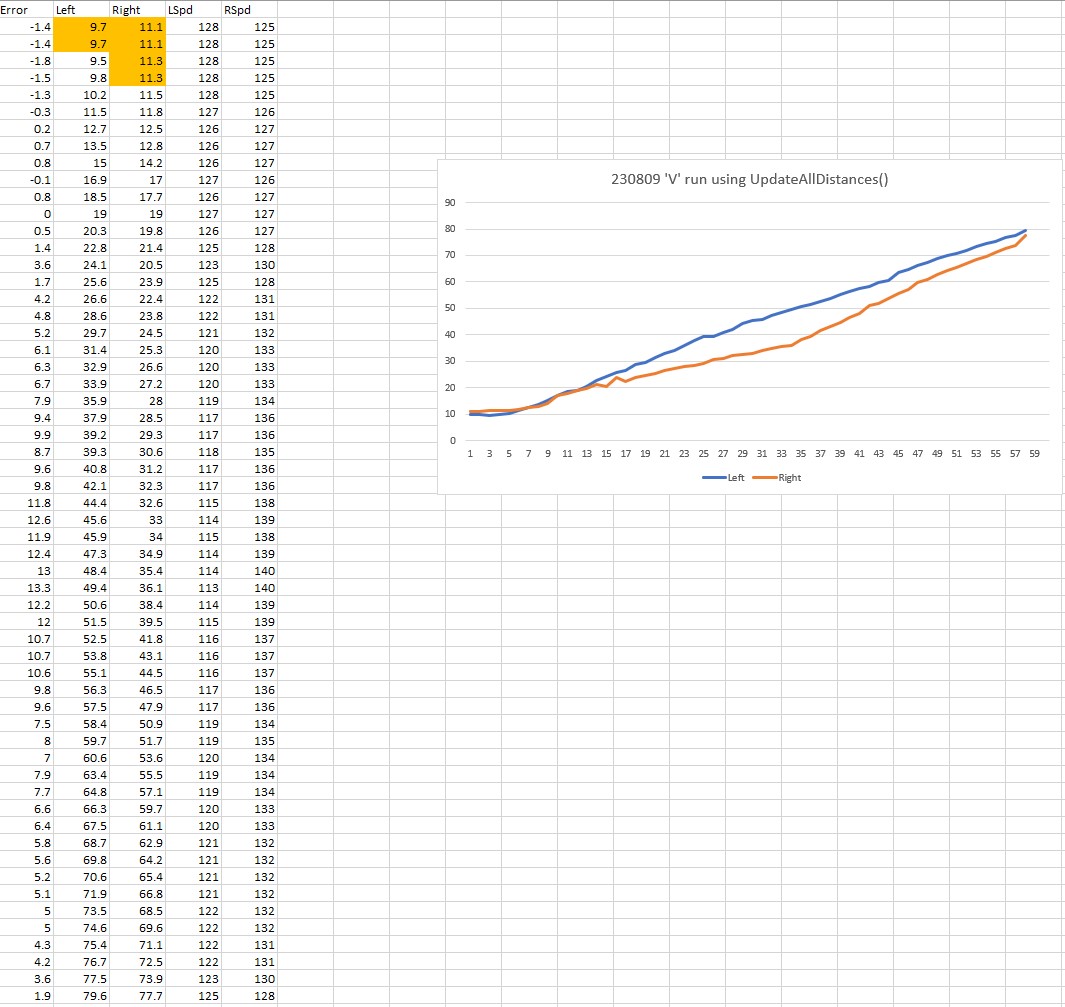
Sec LCen RCen Deg RF RR RStr Front Rear FVar RVar LSpd RSpd ACODE TRKDIR
0.3 182.6 14.2 0.0 14.0 13.8 0.02 454 68 69489 12191 0 127 NONE RIGHT
0.4 181.8 14.1 -0.6 13.8 13.4 0.04 456 68 65357 11925 0 127 NONE RIGHT
0.4 181.8 13.9 -2.7 13.7 13.5 0.02 445 68 61509 11713 0 127 NONE RIGHT
0.5 180.8 13.9 -6.8 14.6 13.4 0.12 424 68 58007 11554 0 127 NONE RIGHT
0.5 172.4 14.5 -11.2 15.8 13.5 0.14 326 68 55444 11439 11 127 NONE RIGHT
0.6 110.4 15.6 -15.1 15.8 13.5 0.23 255 69 53916 11366 41 108 NONE RIGHT
0.6 89.2 16.5 -20.2 17.3 13.6 0.37 216 71 53184 11328 83 66 NONE RIGHT
0.7 83.5 18.4 -24.4 19.6 14.8 0.48 193 74 53068 11323 121 28 NONE RIGHT
0.7 84.6 18.9 -26.1 18.0 15.9 0.21 178 74 53454 11353 61 88 NONE RIGHT
0.8 84.2 18.6 -26.3 20.1 17.1 0.30 176 76 54136 11411 80 69 NONE RIGHT
0.8 84.8 20.0 -26.1 22.8 16.6 0.49 175 80 55080 11484 127 18 NONE RIGHT
0.9 85.4 22.6 -26.0 23.5 17.7 0.51 172 83 56296 11574 127 2 NONE RIGHT
0.9 84.3 24.0 -25.1 24.5 19.7 0.48 172 85 57720 11685 127 0 NONE RIGHT
1.0 84.2 24.0 -176.8 25.2 21.1 0.41 178 88 59243 11813 127 7 NONE RIGHT
1.0 91.2 24.5 -19.8 25.2 21.9 0.33 186 89 60816 11956 121 28 NONE RIGHT
1.1 117.6 25.3 -16.6 25.6 22.3 0.33 197 91 62383 12114 127 22 NONE RIGHT
1.1 174.7 25.6 -13.2 25.8 22.8 0.30 217 93 63813 12280 124 25 NONE RIGHT
1.2 181.2 25.4 -9.6 25.8 23.4 0.24 238 93 65097 12455 110 39 NONE RIGHT
1.2 181.1 25.9 -5.6 26.7 23.9 0.28 377 94 65250 12641 116 33 NONE RIGHT
1.3 178.9 26.0 -2.4 26.7 24.5 0.22 396 95 65385 12827 110 39 NONE RIGHT
1.3 174.9 25.9 -0.1 26.4 24.9 0.15 415 96 65501 13009 86 63 NONE RIGHT
1.4 170.7 26.8 2.4 26.4 25.2 0.12 423 98 65638 13181 82 67 NONE RIGHT
1.4 163.2 26.5 4.2 26.5 26.0 0.04 437 101 65761 13339 62 87 NONE RIGHT
1.5 155.0 27.1 5.3 26.1 26.5 0.00 444 102 65882 13482 54 95 NONE RIGHT
1.5 147.6 26.9 5.3 26.4 26.6 -0.02 445 105 66002 13603 40 109 NONE RIGHT
1.6 144.5 27.2 4.7 26.5 26.8 -0.03 441 107 66118 13698 43 106 NONE RIGHT
1.6 140.2 26.9 4.2 26.5 26.6 -0.01 433 110 66221 13764 43 106 NONE RIGHT
1.7 140.3 26.7 3.2 26.1 26.2 -0.01 423 112 66296 13798 43 106 NONE RIGHT
1.7 140.2 26.6 1.8 26.0 26.1 -0.01 413 114 66319 13793 43 106 NONE RIGHT
1.8 141.9 27.0 0.4 26.8 25.9 0.09 400 119 66277 13744 83 66 NONE RIGHT
1.8 140.9 26.6 -0.9 26.8 26.2 0.06 390 121 66130 13650 69 81 NONE RIGHT
1.9 141.2 27.7 -1.3 27.3 26.7 0.06 387 123 65816 13507 74 75 NONE RIGHT
1.9 141.2 28.1 -1.7 27.6 26.7 0.09 375 125 65344 13311 91 58 NONE RIGHT
2.0 139.4 28.6 -1.5 28.3 26.8 0.15 371 128 64641 13058 105 44 NONE RIGHT
2.0 138.0 29.1 -1.2 28.2 27.0 0.12 372 130 63654 12743 103 46 NONE RIGHT
2.1 135.1 28.4 -0.5 28.4 27.6 0.08 375 133 62342 12361 89 60 NONE RIGHT
2.1 132.3 28.6 0.5 29.0 28.0 0.10 378 136 60674 11909 95 54 NONE RIGHT
2.2 131.5 28.9 1.3 29.0 27.8 0.12 383 138 58614 11380 96 54 NONE RIGHT
2.2 130.1 29.7 2.2 28.5 28.1 0.02 387 140 56135 10772 76 73 NONE RIGHT
2.3 129.3 28.8 3.1 28.8 28.4 0.01 386 143 53213 10080 65 84 NONE RIGHT
2.3 128.5 29.1 3.4 28.7 28.5 0.02 388 145 49807 9298 74 75 NONE RIGHT
2.4 128.7 29.0 3.5 28.7 28.7 0.00 386 148 45885 8421 68 81 NONE RIGHT
2.4 127.1 29.0 3.2 28.7 28.5 0.02 376 150 41414 7445 74 75 NONE RIGHT
2.5 127.0 29.2 3.2 29.1 28.9 0.02 378 152 36335 6364 75 75 NONE RIGHT
2.5 127.5 30.3 3.0 28.9 29.0 -0.01 374 157 30611 5178 71 78 NONE RIGHT
2.6 128.3 29.1 3.2 29.4 28.8 0.06 368 160 24195 3877 88 62 NONE RIGHT
2.6 128.2 29.4 3.3 29.6 29.4 0.02 370 162 17038 2459 75 74 NONE RIGHT
2.7 128.3 29.6 3.6 30.6 29.1 0.15 370 165 9097 918 111 38 NONE RIGHT
2.7 128.5 30.0 4.1 34.7 29.4 0.53 370 167 8890 956 127 0 NONE RIGHT
ANOMALY_EXCESS_STEER_VAL case detected
2.8 128.6 33.5 5.0 158.0 29.1 1.00 370 170 8655 993 127 0 EXCESS_STEER_VAL RIGHT
Stopping Motors! Error Code is EXCESS_STEER_VAL
2.8: Top of loop() - calling UpdateAllEnvironmentParameters()
Battery Voltage = 8.03
Just after UpdateAllEnvironmentParameters() at top of loop() 3.0: gl_Left/RightCenterCm = 78.8/174.2, Left/RightSteerVal = -1.00/1.00
IRHomingValTotalAvg = 42
Top of loop() with anomaly code ANOMALY_EXCESS_STEER_VAL
Calling RotateToParallelOrientation(TRACKING_LEFT)
8.7: gl_Left/RightCenterCm = 78.4/197.3, Left/RightSteerVal = -0.32/0.76
TrackLeftWallOffset(350.0, 0.0, 20.0, 30) called
TrackLeftWallOffset: Start tracking offset of 30cm at 8.7
Calling CaptureWallOffset(TRACKING_LEFT, 78.4)
Hdg Dist
After SpinTurn, Hdg/Dist = -54.0/82
MTFD: at start, tgt = 30cm, curr_dist = 83, front/rear var = 83325.0/13328.0
MTFD: Stopped with front dist = 29
End of CaptureWallOffset
Just after CaptureWallOffset(TRACKING_LEFT, 25.6)
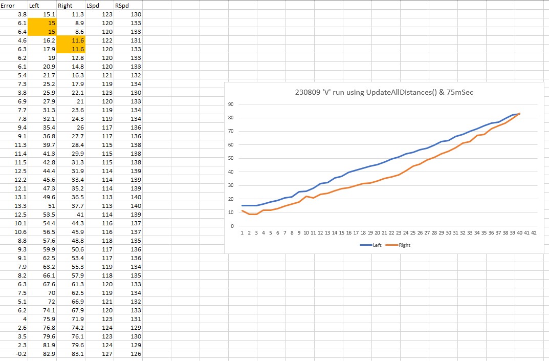
Sec LCen RCen Deg LF LR LStr Front Rear FVar RVar LSpd RSpd ACODE TRKDIR
19.0 25.6 80.4 18.0 24.9 25.0 -0.01 353 255 2317 2521 111 38 NONE LEFT
19.1 25.7 80.6 18.8 24.5 25.3 -0.08 375 255 4795 2587 127 13 NONE LEFT
19.1 25.7 81.7 20.1 24.7 25.1 -0.04 478 256 8781 2643 124 25 NONE LEFT
19.2 25.9 81.7 22.4 24.9 24.9 0.00 467 258 12404 2701 110 39 NONE LEFT
19.2 25.7 83.0 25.2 25.1 25.3 -0.02 457 259 15698 2777 116 33 NONE LEFT
19.3 25.5 86.8 27.5 25.4 25.0 0.04 444 255 18627 2819 97 52 NONE LEFT
19.3 26.6 214.0 31.4 26.1 25.2 0.09 314 147 19792 2562 72 77 NONE LEFT
19.4 26.6 214.0 32.6 26.1 25.2 0.09 196 73 20026 2331 71 78 NONE LEFT
19.4 27.1 229.6 33.7 27.4 26.6 0.08 189 66 20199 2404 68 81 NONE LEFT
19.5 28.1 229.0 34.1 28.9 26.6 0.23 184 64 20319 2478 25 124 NONE LEFT
19.5 28.1 221.4 33.5 30.0 28.2 0.09 186 64 20422 2549 55 94 NONE LEFT
19.6 29.2 153.4 32.7 31.1 28.1 0.19 182 66 20488 2614 31 118 NONE LEFT
19.6 31.3 86.9 31.7 31.7 29.6 0.21 185 69 20540 2670 9 127 NONE LEFT
19.7 31.6 79.6 30.2 32.3 29.9 0.24 185 77 20569 2707 5 127 NONE LEFT
19.7 32.4 76.0 28.0 32.5 30.7 0.18 425 87 22544 2729 11 127 NONE LEFT
19.8 32.8 73.5 25.2 32.8 31.0 0.18 425 106 24381 2732 11 127 NONE LEFT
19.8 32.9 71.8 21.2 32.6 31.3 0.13 435 259 26202 3095 21 127 NONE LEFT
19.9 32.8 68.6 17.4 33.0 32.1 0.09 433 283 27848 3585 29 120 NONE LEFT
19.9 32.8 68.6 14.4 32.8 32.4 0.04 289 286 28046 4069 46 104 NONE LEFT
20.0 34.0 67.4 11.0 33.0 33.3 -0.03 265 281 28048 4490 56 93 NONE LEFT
20.0 34.5 66.7 8.2 33.7 33.6 0.01 242 280 27897 4884 44 105 NONE LEFT
20.1 35.1 66.0 6.7 32.9 34.3 -0.14 235 280 27678 5262 93 57 NONE LEFT
20.1 34.8 65.7 5.2 33.5 34.8 -0.13 228 283 27388 5632 99 50 NONE LEFT
20.2 34.8 66.1 5.0 33.8 34.7 -0.09 220 284 27038 5984 79 70 NONE LEFT
20.2 34.7 66.6 5.4 33.2 34.8 -0.16 222 285 26660 6319 108 41 NONE LEFT
20.3 34.0 66.8 5.8 32.2 34.0 -0.18 220 289 26243 6650 123 26 NONE LEFT
20.3 33.1 66.8 6.5 32.0 33.7 -0.16 222 291 25797 6961 117 32 NONE LEFT
20.4 33.1 66.9 7.8 31.4 33.0 -0.10 221 294 25313 7265 97 52 NONE LEFT
20.4 32.2 67.4 9.5 31.6 31.9 -0.03 227 294 24810 7541 72 77 NONE LEFT
20.5 32.4 67.0 11.2 30.9 31.9 -0.10 231 301 24283 7824 101 48 NONE LEFT
20.5 32.9 66.9 11.7 31.4 31.5 -0.01 237 305 23729 8091 66 83 NONE LEFT
20.6 32.1 66.7 12.6 30.9 32.4 -0.15 232 307 23133 8341 117 32 NONE LEFT
20.6 31.8 65.9 12.9 31.0 32.2 -0.12 232 308 22504 8554 117 32 NONE LEFT
20.7 32.2 66.6 13.8 30.8 32.6 -0.18 237 309 21848 8740 127 13 NONE LEFT
20.7 31.7 66.6 15.0 30.7 31.6 -0.09 238 315 21164 8929 101 48 NONE LEFT
20.8 31.1 66.9 17.0 30.4 31.3 -0.09 249 313 20459 9079 99 50 NONE LEFT
20.8 31.1 66.4 18.2 29.9 31.0 -0.11 265 317 19741 9205 112 37 NONE LEFT
20.9 30.6 66.4 19.8 30.0 30.5 -0.05 378 319 19438 9326 93 56 NONE LEFT
20.9 30.6 65.8 20.7 30.1 30.5 -0.05 398 306 19163 9349 92 57 NONE LEFT
21.0 31.4 65.9 21.7 30.3 31.1 -0.10 391 310 18735 9357 109 41 NONE LEFT
21.0 31.0 65.6 22.7 30.8 30.4 -0.01 386 275 18171 9219 73 76 NONE LEFT
21.1 31.9 65.2 23.5 31.0 31.0 0.00 384 255 17503 9028 68 81 NONE LEFT
21.1 31.8 65.3 24.4 32.4 31.4 0.10 374 134 16698 8945 41 108 NONE LEFT
21.2 33.5 64.5 24.0 38.2 31.7 0.65 372 133 15801 8889 0 127 NONE LEFT
ANOMALY_EXCESS_STEER_VAL case detected
21.2 35.9 63.7 23.1 55.7 32.6 1.00 375 132 14828 8808 0 127 EXCESS_STEER_VAL LEFT
Stopping Motors! Error Code is EXCESS_STEER_VAL
Just after UpdateAllEnvironmentParameters() at top of loop() 21.3: gl_Left/RightCenterCm = 35.9/63.7, Left/RightSteerVal = 1.00/-0.26
gl_LeftCenterCm <= gl_RightCenterCm --> Calling TrackLeftWallOffset()
TrackLeftWallOffset(350.0, 0.0, 20.0, 30) called
TrackLeftWallOffset: Start tracking offset of 30cm at 21.3
Just after CaptureWallOffset(TRACKING_LEFT, 35.9)
Sec LCen RCen Deg LF LR LStr Front Rear FVar RVar LSpd RSpd ACODE TRKDIR
ANOMALY_EXCESS_STEER_VAL case detected
21.4 69.0 61.3 19.2 102.2 35.0 1.00 372 203 13745 8573 0 127 EXCESS_STEER_VAL LEFT
Stopping Motors! Error Code is EXCESS_STEER_VAL
21.4: Top of loop() - calling UpdateAllEnvironmentParameters()
Battery Voltage = 8.05
Just after UpdateAllEnvironmentParameters() at top of loop() 21.6: gl_Left/RightCenterCm = 126.1/60.7, Left/RightSteerVal = -1.00/0.02
IRHomingValTotalAvg = 64
Top of loop() with anomaly code ANOMALY_EXCESS_STEER_VAL
Calling RotateToParallelOrientation(TRACKING_RIGHT)
Moving forward 'one more skosh'
27151: gl_Left/RightCenterCm = 133.4/57.1, Left/RightSteerVal = -1.00/-0.07
TrackRightWallOffset(350.0, 0.0, 20.0, 30) called
TrackRightWallOffset: Start tracking offset of 30cm at 27.2
Calling CaptureWallOffset(TRACKING_RIGHT, 57.1)
Hdg Dist
After SpinTurn, Hdg/Dist = 95.8/58
MTFD: at start, tgt = 30cm, curr_dist = 58, front/rear var = 83325.0/13328.0
MTFD: Stopped with front dist = 30
End of CaptureWallOffset
Just after CaptureWallOffset(TRACKING_RIGHT, 225.4)
Sec LCen RCen Deg RF RR RStr Front Rear FVar RVar LSpd RSpd ACODE TRKDIR
ENTERING COMMAND MODE:
0 = 180 deg CCW Turn
1 = 180 deg CW Turn
A = Abort - Reboots Processor
/ = Forward
.(dot) = Reverse
Faster
8
Left 4 5 6 Right
2
Slower
Setting both motors to reverse
gl_pSerPort now points to active Serial (USB or Wixel)
7950: Starting setup() for WallE3_Complete_V4.ino
Checking for MPU6050 IMU at I2C Addr 0x68
MPU6050 connection successful
Initializing DMP...
Enabling DMP...
DMP ready! Waiting for MPU6050 drift rate to settle...
Calibrating...Retrieving Calibration Values
Msec Hdg
10575 0.047 0.048
MPU6050 Ready at 10.58 Sec with delta = -0.001
Checking for Teensy 3.5 VL53L0X Controller at I2C addr 0x20
Teensy available at 11676 with gl_bVL53L0X_TeensyReady = 1. Waiting for Teensy setup() to finish
11679: got 1 from VL53L0X Teensy
Teensy setup() finished at 11781 mSec
VL53L0X Teensy Ready at 11783
Checking for Garmin LIDAR at Wire2 I2C addr 0x62
LIDAR Responded to query at Wire2 address 0x62!
Setting LIDAR acquisition repeat value to 0x02 for <100mSec measurement repeat delay
Initializing Front Distance Array...Done
Initializing Rear Distance Array...Done
Initializing Left/Right Distance Arrays...Done
Checking for Teensy 3.2 IRDET Controller at I2C addr 0x8
11832: IRDET Teensy Not Avail...
IRDET Teensy Ready at 11935
Fin1/Fin2/SteeringVal = 32 44 -0.4444
11937: Initializing IR Beam Total Value Averaging Array...Done
11940: Initializing IR Beam Steering Value Averaging Array...Done
Battery Voltage = 8.04
14148: End of setup(): Elapsed run time set to 0
0.0: Top of loop() - calling UpdateAllEnvironmentParameters()
Battery Voltage = 8.03
Just after UpdateAllEnvironmentParameters() at top of loop() 0.2: gl_Left/RightCenterCm = 181.1/20.6, Left/RightSteerVal = -1.00/0.07
IRHomingValTotalAvg = 61
Just after UpdateAllEnvironmentParameters() at top of loop() 0.2: gl_Left/RightCenterCm = 181.1/20.6, Left/RightSteerVal = -1.00/0.07
TrackRightWallOffset(350.0, 0.0, 20.0, 30) called
TrackRightWallOffset: Start tracking offset of 30cm at 0.3
Just after CaptureWallOffset(TRACKING_RIGHT, 181.1)
Sec LCen RCen Deg RF RR RStr Front Rear FVar RVar LSpd RSpd ACODE TRKDIR
0.3 181.3 20.7 -0.0 20.7 19.7 0.10 441 72 69587 12128 42 108 NONE RIGHT
0.4 181.3 20.7 -0.4 20.6 19.7 0.09 437 72 65527 11841 36 113 NONE RIGHT
0.4 180.2 20.1 -1.5 20.4 19.6 0.08 428 72 61761 11607 33 116 NONE RIGHT
0.5 180.2 20.9 -3.3 21.0 19.3 0.17 419 73 58300 11421 56 93 NONE RIGHT
0.5 179.0 20.9 -5.8 21.3 19.8 0.15 405 73 55181 11279 50 99 NONE RIGHT
0.6 173.4 21.8 -7.8 22.1 20.2 0.19 405 75 52332 11175 70 79 NONE RIGHT
0.6 169.0 22.5 -9.5 22.7 20.3 0.24 400 76 49781 11111 88 62 NONE RIGHT
0.7 167.6 22.9 -10.3 23.9 21.4 0.25 394 79 47534 11080 92 57 NONE RIGHT
0.7 165.6 24.4 -10.1 25.3 21.7 0.29 396 81 45534 11080 112 37 NONE RIGHT
0.8 173.7 25.6 -9.6 26.3 22.4 0.29 396 83 43787 11108 120 29 NONE RIGHT
0.8 178.1 25.7 -8.5 26.8 23.4 0.29 395 84 42292 11163 120 29 NONE RIGHT
0.9 181.0 26.3 -6.8 27.6 23.8 0.30 384 87 41114 11240 127 19 NONE RIGHT
0.9 183.1 26.4 -4.3 27.3 24.5 0.28 399 89 40055 11339 124 25 NONE RIGHT
1.0 183.3 26.7 -1.4 27.3 25.1 0.22 396 91 39233 11455 110 39 NONE RIGHT
1.0 182.1 27.1 1.3 27.7 25.8 0.19 423 92 38433 11586 106 43 NONE RIGHT
1.1 176.2 26.9 3.7 27.7 26.1 0.16 431 94 37773 11734 96 53 NONE RIGHT
1.1 168.6 27.1 6.2 27.5 26.5 0.10 443 98 37218 11878 89 60 NONE RIGHT
1.2 159.9 28.1 8.1 27.7 27.2 0.05 465 101 36712 12025 79 70 NONE RIGHT
1.3 153.4 28.0 9.8 27.8 27.1 0.07 487 103 36256 12176 85 64 NONE RIGHT
1.3 143.9 28.5 10.6 27.8 27.8 0.00 584 108 35730 12316 62 87 NONE RIGHT
1.4 142.1 28.0 10.5 27.4 27.8 -0.04 616 110 35320 12453 47 102 NONE RIGHT
1.5 140.4 27.8 9.7 27.2 27.7 -0.05 579 115 34994 12578 37 112 NONE RIGHT
1.5 140.8 27.3 9.2 27.0 27.4 -0.04 460 117 35115 12692 39 110 NONE RIGHT
1.6 140.7 27.9 8.5 27.4 27.0 0.04 453 120 35353 12793 66 83 NONE RIGHT
1.6 140.8 27.9 7.5 27.4 26.8 0.06 440 122 35725 12875 74 75 NONE RIGHT
1.6 140.8 28.1 6.9 27.5 27.0 0.05 439 122 36140 12944 78 71 NONE RIGHT
1.7 140.6 28.0 6.5 27.5 26.6 0.09 429 124 36633 12989 91 58 NONE RIGHT
1.7 139.6 28.0 6.4 27.5 26.6 0.09 427 127 37130 13007 92 57 NONE RIGHT
1.8 139.2 28.0 6.5 27.9 27.1 0.08 427 129 37596 12992 89 60 NONE RIGHT
1.8 138.6 28.2 6.8 28.4 27.6 0.08 427 132 38004 12941 89 61 NONE RIGHT
1.8 138.6 28.6 7.1 27.9 27.2 0.07 422 132 38360 12856 85 64 NONE RIGHT
1.9 137.3 28.8 7.5 28.0 27.1 0.09 419 136 38622 12722 92 57 NONE RIGHT
1.9 136.0 28.1 7.7 27.8 27.8 0.00 429 140 38691 12539 62 87 NONE RIGHT
2.0 135.6 28.1 7.7 28.4 27.5 0.09 424 141 38621 12306 90 59 NONE RIGHT
2.0 135.8 28.8 7.5 28.0 27.7 0.03 415 144 38403 12016 72 77 NONE RIGHT
2.1 136.9 29.1 7.9 28.0 27.8 0.02 417 146 37944 11666 74 75 NONE RIGHT
2.1 136.5 29.3 8.1 28.4 27.7 0.07 415 149 37233 11252 91 58 NONE RIGHT
2.2 136.5 28.9 8.5 28.2 28.2 0.00 411 152 36246 10769 62 87 NONE RIGHT
2.2 136.7 28.9 8.9 28.5 28.2 0.03 424 155 34874 10213 70 79 NONE RIGHT
2.3 136.8 29.0 9.1 28.9 28.3 0.05 420 157 33158 9579 84 65 NONE RIGHT
2.3 137.6 28.5 9.3 28.9 28.0 0.09 422 160 31040 8864 92 57 NONE RIGHT
2.4 138.0 28.7 9.8 28.4 28.5 -0.01 428 165 28475 8064 59 90 NONE RIGHT
2.5 138.3 28.8 10.4 28.4 28.3 0.01 467 167 25384 7174 64 85 NONE RIGHT
2.5 136.5 28.6 10.4 29.4 28.8 0.06 520 170 21852 6190 81 69 NONE RIGHT
2.6 124.9 29.4 10.3 32.5 28.2 0.43 488 175 17804 5110 127 0 NONE RIGHT
ANOMALY_EXCESS_STEER_VAL case detected
2.7 113.2 43.1 11.0 152.7 28.2 1.00 539 178 13330 3925 127 0 EXCESS_STEER_VAL RIGHT
Stopping Motors! Error Code is EXCESS_STEER_VAL
2.7: Top of loop() - calling UpdateAllEnvironmentParameters()
Battery Voltage = 7.98
Just after UpdateAllEnvironmentParameters() at top of loop() 2.9: gl_Left/RightCenterCm = 86.1/167.0, Left/RightSteerVal = -0.66/0.74
IRHomingValTotalAvg = 67
Top of loop() with anomaly code ANOMALY_EXCESS_STEER_VAL
Calling RotateToParallelOrientation(TRACKING_LEFT)
Moving forward 'one more skosh'
9.1: gl_Left/RightCenterCm = 133.2/173.3, Left/RightSteerVal = -1.00/-1.00
TrackLeftWallOffset(350.0, 0.0, 20.0, 30) called
TrackLeftWallOffset: Start tracking offset of 30cm at 9.1
Calling CaptureWallOffset(TRACKING_LEFT, 133.2)
Hdg Dist
After SpinTurn, Hdg/Dist = -36.5/257
MTFD: at start, tgt = 30cm, curr_dist = 258, front/rear var = 83325.0/13328.0
ENTERING COMMAND MODE:
0 = 180 deg CCW Turn
1 = 180 deg CW Turn
A = Abort - Reboots Processor
/ = Forward
.(dot) = Reverse
Faster
8
Left 4 5 6 Right
2
Slower
gl_pSerPort now points to active Serial (USB or Wixel)
7950: Starting setup() for WallE3_Complete_V4.ino
Checking for MPU6050 IMU at I2C Addr 0x68
MPU6050 connection successful
Initializing DMP...
Enabling DMP...
DMP ready! Waiting for MPU6050 drift rate to settle...
Calibrating...Retrieving Calibration Values
Msec Hdg
10577 0.031 0.039
MPU6050 Ready at 10.58 Sec with delta = -0.007
Checking for Teensy 3.5 VL53L0X Controller at I2C addr 0x20
Teensy available at 11677 with gl_bVL53L0X_TeensyReady = 1. Waiting for Teensy setup() to finish
11680: got 1 from VL53L0X Teensy
Teensy setup() finished at 11782 mSec
VL53L0X Teensy Ready at 11784
Checking for Garmin LIDAR at Wire2 I2C addr 0x62
LIDAR Responded to query at Wire2 address 0x62!
Setting LIDAR acquisition repeat value to 0x02 for <100mSec measurement repeat delay
Initializing Front Distance Array...Done
Initializing Rear Distance Array...Done
Initializing Left/Right Distance Arrays...Done
Checking for Teensy 3.2 IRDET Controller at I2C addr 0x8
11836: IRDET Teensy Not Avail...
IRDET Teensy Ready at 11939
Fin1/Fin2/SteeringVal = 26 26 0.0286
11941: Initializing IR Beam Total Value Averaging Array...Done
11944: Initializing IR Beam Steering Value Averaging Array...Done
Battery Voltage = 8.03
14152: End of setup(): Elapsed run time set to 0
0.0: Top of loop() - calling UpdateAllEnvironmentParameters()
Battery Voltage = 8.04
Just after UpdateAllEnvironmentParameters() at top of loop() 0.2: gl_Left/RightCenterCm = 191.2/15.0, Left/RightSteerVal = -1.00/-0.04
IRHomingValTotalAvg = 55
Just after UpdateAllEnvironmentParameters() at top of loop() 0.2: gl_Left/RightCenterCm = 191.2/15.0, Left/RightSteerVal = -1.00/-0.04
TrackRightWallOffset(350.0, 0.0, 20.0, 30) called
TrackRightWallOffset: Start tracking offset of 30cm at 0.3
Just after CaptureWallOffset(TRACKING_RIGHT, 191.2)
Sec LCen RCen Deg RF RR RStr Front Rear FVar RVar LSpd RSpd ACODE TRKDIR
0.3 191.6 14.9 -0.0 14.3 14.8 -0.05 487 71 69292 12138 0 127 NONE RIGHT
0.4 190.9 14.9 -0.3 14.6 15.1 -0.05 492 71 65048 11851 0 127 NONE RIGHT
0.4 191.1 15.2 -2.3 14.5 15.2 -0.07 485 71 61044 11623 0 127 NONE RIGHT
0.5 190.9 14.5 -5.3 14.5 14.6 -0.01 457 71 57358 11442 0 127 NONE RIGHT
0.5 190.3 15.0 -9.4 15.3 14.6 0.07 438 72 54004 11310 0 127 NONE RIGHT
0.6 188.8 15.6 -14.3 16.5 14.7 0.13 409 73 51066 11216 14 127 NONE RIGHT
0.7 182.6 17.5 -19.6 18.1 15.5 0.26 378 74 48608 11168 58 91 NONE RIGHT
0.7 92.1 17.5 -23.9 18.1 15.5 0.26 247 74 47748 11158 60 89 NONE RIGHT
0.7 89.0 18.1 -28.3 20.6 16.0 0.21 213 77 47634 11178 57 92 NONE RIGHT
0.8 86.8 19.9 -30.9 21.9 17.8 0.28 188 78 48161 11226 80 69 NONE RIGHT
0.8 89.1 21.5 -32.5 23.3 18.0 0.53 183 76 49024 11324 127 5 NONE RIGHT
0.9 90.0 23.2 -32.7 24.8 19.2 0.56 179 74 50188 11465 127 0 NONE RIGHT
0.9 89.0 24.4 -32.0 25.9 20.9 0.50 180 74 51558 11635 127 0 NONE RIGHT
1.0 89.9 25.1 -30.5 26.7 21.8 0.49 181 78 53112 11805 127 0 NONE RIGHT
1.0 92.7 25.8 -27.8 27.1 22.7 0.44 189 89 54726 11948 127 0 NONE RIGHT
1.1 93.5 26.3 -24.6 27.6 23.3 0.43 206 92 56258 12097 127 0 NONE RIGHT
1.1 117.7 26.7 -20.7 27.5 23.8 0.37 240 94 57487 12259 127 7 NONE RIGHT
1.2 178.6 26.5 -15.6 27.3 24.2 0.31 366 95 57617 12427 127 21 NONE RIGHT
1.2 186.6 26.1 -11.1 27.1 24.7 0.24 377 96 57790 12600 117 32 NONE RIGHT
1.3 186.2 26.8 -6.7 26.7 25.1 0.16 397 97 57941 12779 97 52 NONE RIGHT
1.3 181.3 26.6 -3.5 26.9 25.5 0.14 416 97 58074 12957 89 60 NONE RIGHT
1.4 175.9 27.3 0.5 27.0 26.2 0.07 438 100 58174 13126 79 70 NONE RIGHT
1.4 164.3 27.5 2.3 26.7 27.7 -0.10 452 101 58273 13282 22 127 NONE RIGHT
1.5 151.2 27.9 2.8 26.9 27.6 -0.07 447 103 58429 13422 28 121 NONE RIGHT
1.5 148.6 27.5 2.2 27.0 27.9 -0.09 453 106 58581 13539 22 127 NONE RIGHT
1.6 146.8 27.2 1.4 27.3 27.3 0.00 454 108 58730 13634 52 97 NONE RIGHT
1.6 146.3 27.0 -0.2 26.1 27.1 -0.10 433 110 58936 13699 21 127 NONE RIGHT
1.7 146.8 27.1 -1.6 26.2 26.7 -0.05 430 114 59108 13727 35 114 NONE RIGHT
1.7 148.7 26.8 -3.7 26.4 26.3 0.01 407 117 59311 13719 49 100 NONE RIGHT
1.8 150.7 26.3 -5.5 26.7 26.2 0.05 397 119 59461 13672 63 86 NONE RIGHT
1.8 148.9 27.0 -7.1 26.9 26.0 0.09 379 121 59573 13579 84 65 NONE RIGHT
1.9 152.5 27.5 -8.1 27.9 26.0 0.19 368 123 59578 13438 105 44 NONE RIGHT
1.9 152.8 28.6 -8.3 28.1 26.4 0.17 366 126 59389 13245 113 36 NONE RIGHT
2.0 152.4 27.9 -7.7 28.5 26.9 0.16 361 128 58992 12993 103 46 NONE RIGHT
2.0 149.0 28.1 -6.9 28.4 27.0 0.14 368 130 58286 12680 103 47 NONE RIGHT
2.1 144.5 28.6 -5.6 29.2 27.6 0.16 372 133 57261 12301 109 40 NONE RIGHT
2.1 141.3 28.5 -4.2 29.1 28.1 0.07 384 136 55855 11852 86 63 NONE RIGHT
2.2 138.3 29.3 -2.8 29.2 28.5 0.06 388 138 54076 11327 88 61 NONE RIGHT
2.2 134.6 29.0 -1.8 29.0 28.7 0.03 391 140 51897 10723 79 70 NONE RIGHT
2.3 133.8 28.8 -1.1 28.8 29.0 -0.02 389 143 49296 10033 55 94 NONE RIGHT
2.3 131.3 29.7 -0.7 29.3 28.6 0.07 393 144 46222 9254 90 59 NONE RIGHT
2.4 131.3 29.0 -0.9 29.2 28.9 0.03 385 147 42664 8381 79 70 NONE RIGHT
2.4 131.1 29.2 -1.1 28.6 28.8 -0.02 384 150 38563 7408 62 88 NONE RIGHT
2.5 132.4 29.7 -1.1 29.2 29.1 0.01 381 154 33881 6334 70 79 NONE RIGHT
2.5 130.2 29.2 -1.1 29.0 28.8 0.02 376 156 28575 5150 74 75 NONE RIGHT
2.6 131.8 30.0 -0.9 29.1 29.4 -0.03 373 160 22596 3854 65 84 NONE RIGHT
2.6 132.4 29.0 -0.9 29.2 29.2 0.00 376 162 15895 2437 67 82 NONE RIGHT
2.7 132.8 29.1 -0.9 29.0 28.9 0.01 374 165 8430 898 71 78 NONE RIGHT
2.7 132.7 29.3 -1.3 29.6 29.0 0.06 367 167 8155 939 88 62 NONE RIGHT
2.8 133.4 29.1 -1.6 29.7 29.1 0.06 363 170 7850 979 89 61 NONE RIGHT
2.8 133.3 30.1 -1.7 32.7 28.7 0.40 363 172 7537 1014 127 0 NONE RIGHT
ANOMALY_EXCESS_STEER_VAL case detected
2.9 133.8 32.8 -1.6 154.5 28.8 1.00 357 175 7185 1049 127 0 EXCESS_STEER_VAL RIGHT
Stopping Motors! Error Code is EXCESS_STEER_VAL
2.9: Top of loop() - calling UpdateAllEnvironmentParameters()
Battery Voltage = 7.97
Just after UpdateAllEnvironmentParameters() at top of loop() 3.1: gl_Left/RightCenterCm = 82.5/199.3, Left/RightSteerVal = -1.00/0.79
IRHomingValTotalAvg = 61
Top of loop() with anomaly code ANOMALY_EXCESS_STEER_VAL
Calling RotateToParallelOrientation(TRACKING_LEFT)
Moving forward 'one more skosh'
9.3: gl_Left/RightCenterCm = 92.2/174.2, Left/RightSteerVal = -0.68/-0.13
TrackLeftWallOffset(350.0, 0.0, 20.0, 30) called
TrackLeftWallOffset: Start tracking offset of 30cm at 9.3
Calling CaptureWallOffset(TRACKING_LEFT, 92.2)
Hdg Dist
After SpinTurn, Hdg/Dist = -60.3/108
MTFD: at start, tgt = 30cm, curr_dist = 106, front/rear var = 83325.0/13328.0
MTFD: Stopped with front dist = 30
End of CaptureWallOffset
Just after CaptureWallOffset(TRACKING_LEFT, 11.2)
Sec LCen RCen Deg LF LR LStr Front Rear FVar RVar LSpd RSpd ACODE TRKDIR
20.3 10.9 100.9 3.4 11.0 11.2 -0.04 185 251 125275 4734 127 0 NONE LEFT
20.4 11.2 100.8 3.9 10.4 11.0 -0.06 186 249 121657 4705 127 0 NONE LEFT
20.4 10.8 100.8 5.9 10.8 10.4 0.04 190 232 117422 4659 127 0 NONE LEFT
20.5 10.8 100.2 9.4 10.9 10.9 0.00 206 106 112506 4940 127 0 NONE LEFT
20.5 11.2 100.6 12.7 11.7 10.8 0.09 236 75 106884 5339 127 0 NONE LEFT
20.6 11.6 100.6 16.8 12.9 12.2 0.07 266 59 100592 5778 127 0 NONE LEFT
20.7 13.6 103.6 26.3 14.8 11.1 0.37 403 40 94178 6258 84 65 NONE LEFT
20.7 14.2 107.2 29.8 15.7 11.1 0.37 207 40 86457 6640 78 71 NONE LEFT
20.7 14.2 107.2 32.8 15.7 11.6 0.41 201 32 77889 6971 65 84 NONE LEFT
20.8 15.8 114.5 36.1 18.1 13.7 0.44 184 25 68419 7233 54 95 NONE LEFT
20.8 17.7 132.1 37.2 20.4 15.5 0.49 177 23 57979 7386 30 119 NONE LEFT
20.9 19.0 168.8 36.9 22.1 17.5 0.46 175 23 46510 7397 26 123 NONE LEFT
20.9 20.7 124.1 35.8 23.4 18.6 0.48 174 25 33958 7247 19 127 NONE LEFT
21.0 22.1 115.2 34.2 22.6 19.8 0.28 177 27 20276 6926 52 98 NONE LEFT
21.1 23.6 108.3 31.6 25.1 22.2 0.29 179 32 5412 6406 44 105 NONE LEFT
21.1 24.0 103.7 29.7 25.4 21.7 0.37 205 36 5576 5694 23 126 NONE LEFT
21.1 24.9 100.7 28.8 26.6 22.6 0.40 186 41 5673 5977 12 127 NONE LEFT
21.2 26.2 98.0 26.9 27.2 23.7 0.35 184 44 5758 6230 15 127 NONE LEFT
21.3 27.5 92.5 22.3 28.2 25.4 0.28 292 48 6344 6454 18 127 NONE LEFT
21.3 27.2 90.2 20.0 28.2 25.4 0.28 407 53 7924 6647 19 127 NONE LEFT
21.4 27.2 88.2 16.9 28.5 26.0 0.22 331 59 8712 6807 32 117 NONE LEFT
21.4 28.3 88.2 14.8 28.5 27.1 0.14 240 67 8912 6933 46 103 NONE LEFT
21.4 28.1 85.9 12.2 28.3 26.8 0.15 225 78 9037 7014 43 106 NONE LEFT
21.5 28.3 84.1 9.3 28.4 28.0 0.04 203 94 9082 7049 73 76 NONE LEFT
21.5 28.8 83.1 7.3 28.4 28.6 -0.02 193 127 9088 7035 94 55 NONE LEFT
21.6 29.1 81.5 5.9 28.6 28.6 0.00 187 288 9069 7423 82 67 NONE LEFT
21.6 29.1 80.6 6.0 28.7 29.2 -0.05 181 308 9029 7925 98 51 NONE LEFT
21.7 29.4 80.7 6.7 28.9 29.2 -0.03 182 315 8977 8457 92 57 NONE LEFT
21.7 29.8 80.0 7.1 29.4 29.8 -0.04 181 309 8910 8935 95 54 NONE LEFT
21.8 29.9 79.9 7.0 29.6 29.8 -0.02 179 305 8827 9372 89 60 NONE LEFT
21.8 30.2 79.4 7.6 31.5 29.7 -0.01 179 322 8727 9903 79 70 NONE LEFT
21.9 31.0 79.0 7.9 36.8 30.4 0.64 178 319 8614 10396 0 127 NONE LEFT
ANOMALY_EXCESS_STEER_VAL case detected
21.9 33.7 79.0 7.9 68.8 30.5 1.00 174 312 8485 10829 0 127 EXCESS_STEER_VAL LEFT
Stopping Motors! Error Code is EXCESS_STEER_VAL
Just after UpdateAllEnvironmentParameters() at top of loop() 21.9: gl_Left/RightCenterCm = 33.7/79.0, Left/RightSteerVal = 1.00/-0.17
gl_LeftCenterCm <= gl_RightCenterCm --> Calling TrackLeftWallOffset()
TrackLeftWallOffset(350.0, 0.0, 20.0, 30) called
TrackLeftWallOffset: Start tracking offset of 30cm at 22.0
Just after CaptureWallOffset(TRACKING_LEFT, 33.7)
Sec LCen RCen Deg LF LR LStr Front Rear FVar RVar LSpd RSpd ACODE TRKDIR
ANOMALY_EXCESS_STEER_VAL case detected
22.0 73.9 78.9 5.9 89.7 34.5 1.00 160 317 8333 11274 0 127 EXCESS_STEER_VAL LEFT
Stopping Motors! Error Code is EXCESS_STEER_VAL
22.1: Top of loop() - calling UpdateAllEnvironmentParameters()
Battery Voltage = 7.99
Just after UpdateAllEnvironmentParameters() at top of loop() 22.3: gl_Left/RightCenterCm = 102.3/81.6, Left/RightSteerVal = -1.00/0.13
IRHomingValTotalAvg = 77
Top of loop() with anomaly code ANOMALY_EXCESS_STEER_VAL
Calling RotateToParallelOrientation(TRACKING_RIGHT)
Moving forward 'one more skosh'
25319: gl_Left/RightCenterCm = 104.7/87.0, Left/RightSteerVal = -1.00/-0.02
TrackRightWallOffset(350.0, 0.0, 20.0, 30) called
TrackRightWallOffset: Start tracking offset of 30cm at 25.3
Calling CaptureWallOffset(TRACKING_RIGHT, 87.0)
Hdg Dist
After SpinTurn, Hdg/Dist = 89.1/84
MTFD: at start, tgt = 30cm, curr_dist = 82, front/rear var = 83325.0/13328.0
MTFD: Stopped with front dist = 30
End of CaptureWallOffset
Just after CaptureWallOffset(TRACKING_RIGHT, 57.9)
Sec LCen RCen Deg RF RR RStr Front Rear FVar RVar LSpd RSpd ACODE TRKDIR
35.7 58.1 117.1 -101.5 117.0 123.2 -0.62 189 11 132935 14070 114 35 NONE RIGHT
35.8 58.2 117.2 -101.0 117.3 123.5 -0.62 189 11 132562 14600 117 33 NONE RIGHT
35.8 59.1 118.0 -99.4 117.9 124.6 -0.67 179 11 131935 15069 67 82 NONE RIGHT
35.9 63.0 119.9 -97.4 120.1 126.6 -0.65 181 12 130932 15478 90 59 NONE RIGHT
35.9 68.0 121.7 -96.1 121.6 128.5 -0.69 185 13 129506 15813 52 97 NONE RIGHT
36.0 73.6 122.3 -95.5 122.1 129.4 -0.73 181 15 127668 16061 10 127 NONE RIGHT
36.0 80.2 122.0 -96.2 121.3 129.8 -0.85 182 16 125348 16223 0 127 NONE RIGHT
36.1 84.8 120.1 -97.6 118.6 126.7 -0.81 173 18 122557 16282 0 127 NONE RIGHT
36.1 86.3 117.1 -100.4 116.3 123.2 -0.69 172 20 119205 16236 29 120 NONE RIGHT
36.2 86.3 112.3 -103.9 110.4 118.8 -0.84 177 23 115224 16075 0 127 NONE RIGHT
36.2 79.9 106.0 -107.6 104.6 112.4 -0.78 179 24 110589 15803 0 127 NONE RIGHT
36.3 76.7 102.1 -111.9 97.8 106.8 -0.66 182 26 105255 15408 5 127 NONE RIGHT
36.3 72.9 100.5 -116.5 99.4 101.4 -0.36 182 29 99189 14884 127 0 NONE RIGHT
36.4 68.5 101.1 -121.4 93.2 98.5 -0.53 181 32 92348 14221 127 0 NONE RIGHT
ANOMALY_EXCESS_STEER_VAL case detected
36.4 65.2 97.3 -122.6 82.0 98.4 -1.00 176 34 84689 13413 0 127 EXCESS_STEER_VAL RIGHT
Stopping Motors! Error Code is EXCESS_STEER_VAL
Just after UpdateAllEnvironmentParameters() at top of loop() 36.5: gl_Left/RightCenterCm = 65.2/97.3, Left/RightSteerVal = 0.00/-1.00
gl_LeftCenterCm <= gl_RightCenterCm --> Calling TrackLeftWallOffset()
TrackLeftWallOffset(350.0, 0.0, 20.0, 30) called
TrackLeftWallOffset: Start tracking offset of 30cm at 36.5
Calling CaptureWallOffset(TRACKING_LEFT, 65.2)
Hdg Dist
After SpinTurn, Hdg/Dist = 149.8/89
MTFD: at start, tgt = 30cm, curr_dist = 90, front/rear var = 83325.0/13328.0
MTFD: Stopped with front dist = 30